Today I will be taking apart a Dell Inspiron 11 3147 2-in-1 laptop (model P20T). This guide also works for Dell Inspiron 11 3148 and likely some other models in the Dell Inspiron 11 3000 series computer line.
During the disassembly process I found the following Dell Inspiron 11 3147 3148 design highlight worth mentioning upfront:
– The laptop has only one memory slots available for RAM upgrade.
– There is no memory soldered to the motherboard.
– The cooling fan is a part of the heatsink assembly.
– The DC power jack is replaceable but the harness is routed under the motherboard.
– The keyboard is permanently attached to the top case.
As usual, at the end of this guide you will find a link to the official Dell owner’s manual just in case if you need more detailed laptop disassembly instructions.
Base cover and battery removal
STEP 1.
Remove nine screws securing the base cover. I’m using a Phillips screwdriver #1 which is the main tool in my repair toolbox.

STEP 2.
Start separating the base cover from the top case. Begin around the display hinges area. Use a plastic spudger for that.
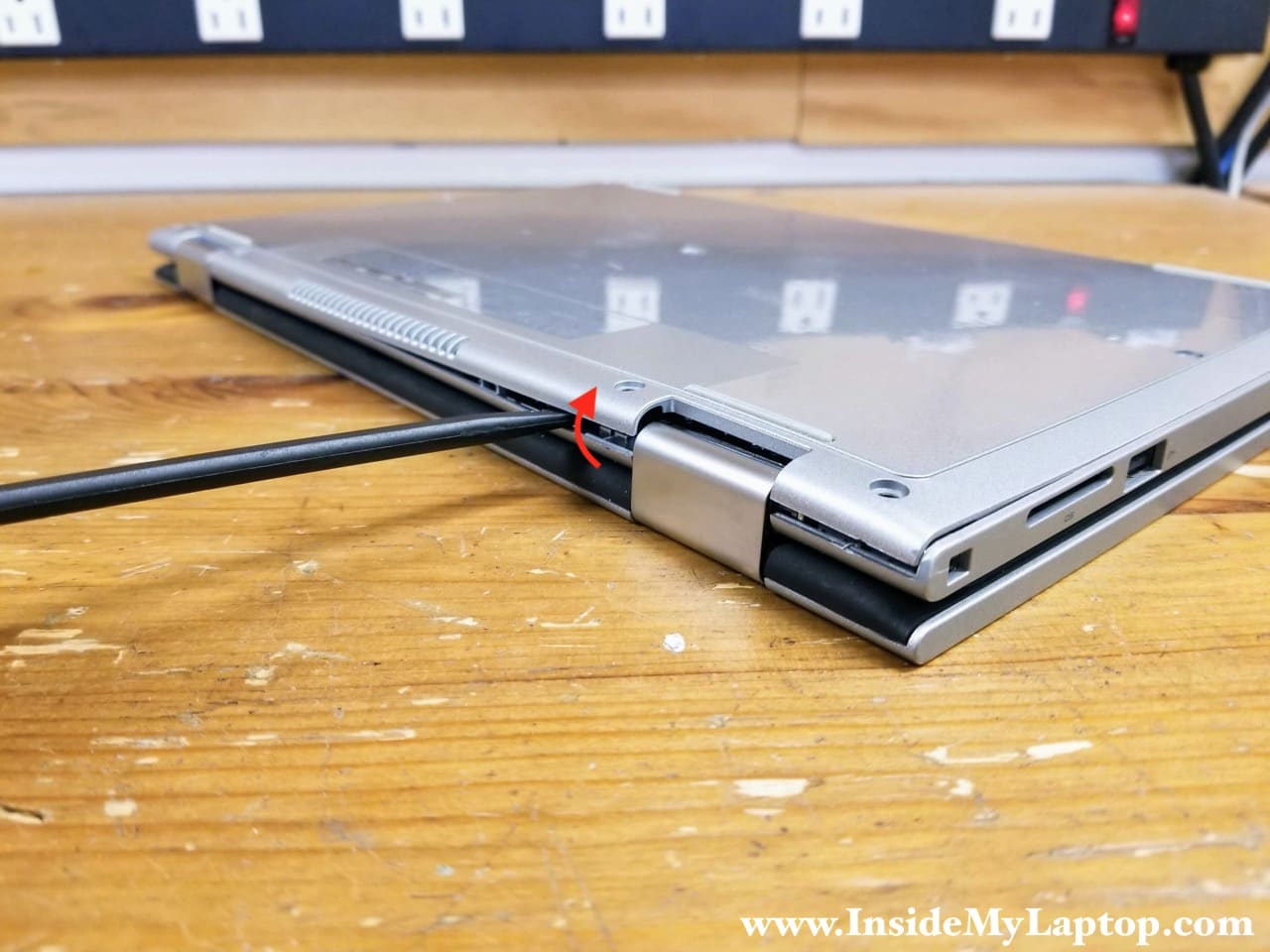
STEP 3.
Continue removing the base cover with your hands. Remove the cover.

STEP 4.
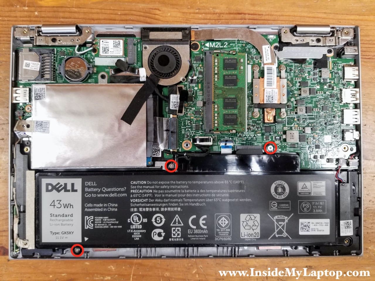
Remove three screws securing the battery.
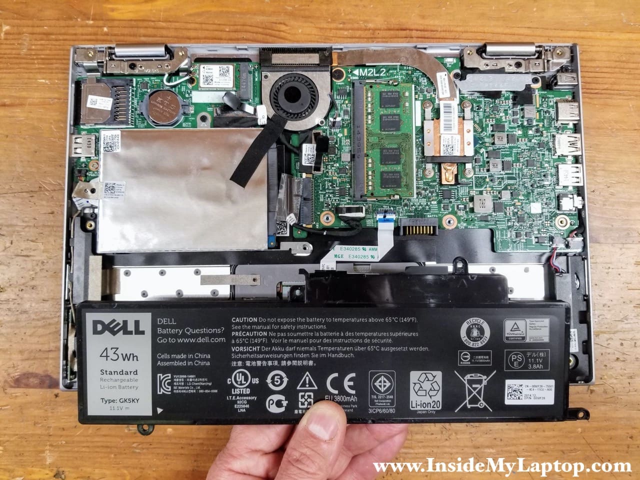
STEP 5.
Lift up and remove the battery from the laptop.
Dell Inspiron 11 3147 3148 2-in-1 battery type: GK5KY. Dell spare part number: 00WF28.
Memory module and hard drive removal
Dell Inspiron 11 3147 laptop reference guide (and Crucial website) says that this model supports up to 4GB RAM but this is not correct. I just tested this laptop with one 8GB DDR3 12800 memory module and it worked for me just fine. All 8GB recognized correctly in Windows 10 OS.
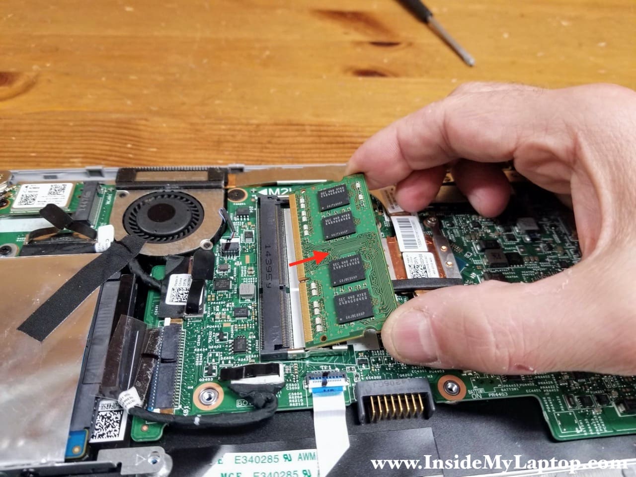
STEP 6.
Pull the memory module out and replace it with a larger capacity memory module if necessary.
STEP 7.
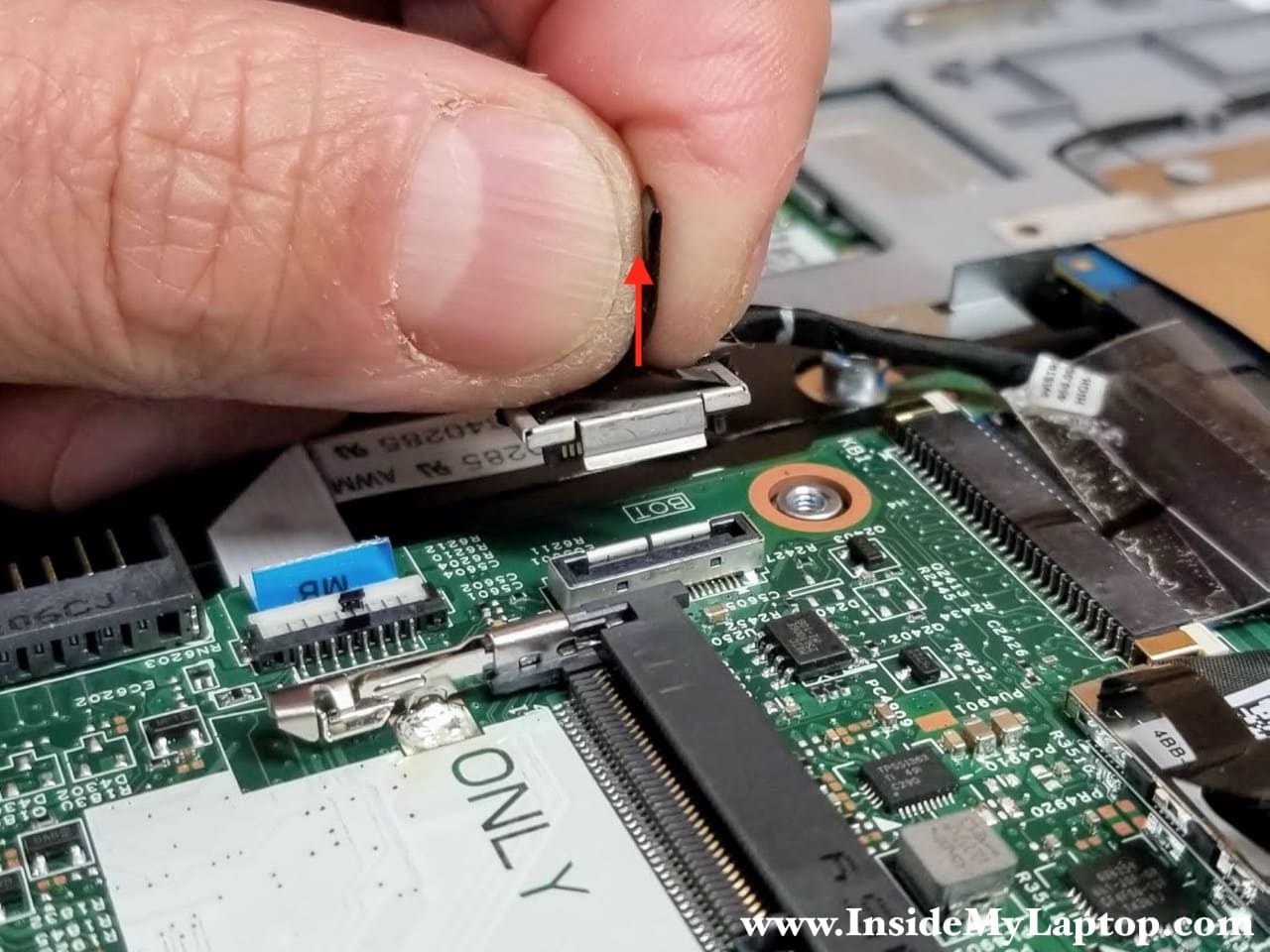
Remove two screws securing the hard drive mounting bracket and disconnect the hard drive cable from the motherboard.
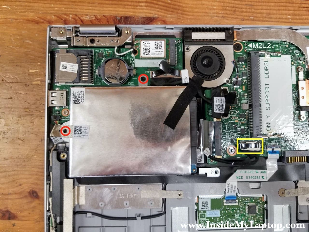
Here’s how to unplug the SATA cable from the motherboard. Pull it up by the black tab located on the top of the connector.
STEP 8.
Remove the hard drive assembly with the cable attached to it.

I would strongly advise replacing the regular 2.5″ spinning hard drive with a 2.5″ solid state drive. You will see a huge difference in the overall laptop performance.
If you decide to upgrade to a solid state drive, you will have to transfer the mounting bracket and the SATA cable to the new drive.

Cooling fan assembly removal
STEP 9.
Loosen four captive screws attaching the heatsink to the motherboard and disconnect the cooling fan cable.

STEP 10.
Carefully separate the heatsink from the processor and remove the cooling fan assembly.
Dell Inspiron 11 3147 cooling fan assembly part number: 00JM58.
Dell Inspiron 11 3148 cooling fan assembly part number: 0KR2R4.

Display panel removal
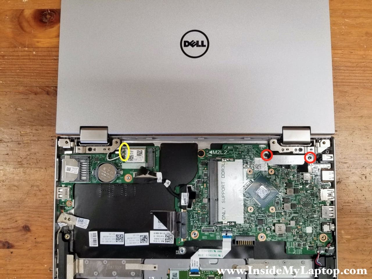
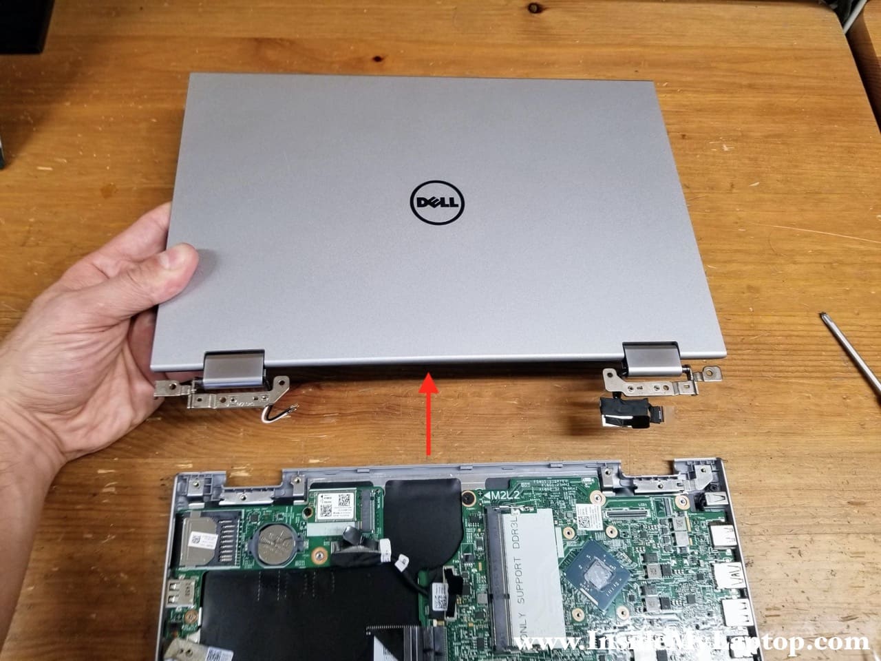
Open the display panel 180 degrees and place the laptop on the desk as shown on the following picture.
Before removing the display it’s necessary to disconnect the wireless card antenna cables from the left side and the display/webcam cables from the right side.
STEP 11.
Remove two screws from the metal bracket covering the display/webcam connectors. Lift up and remove the bracket. Disconnect both cable from the motherboard.
In order to disconnect the wireless card antenna cables simply lift up the cable “head” and un-snap it from the wireless card.

Here’s how to unplug the display cable. The connector has a black tab on the top. Pull the display cable connector up to disconnect it from the motherboard.

The webcam cable connector has to be unlocked first. Lift up the white locking tab at a 90 degree angle (red arrow). Pull the webcam cable out.

STEP 12.
Remove two screws securing the display hinges.

STEP 13.
Lift up the display assembly and remove it.
In the next guide I explain how to remove the touchscreen.
I/O board and motherboard removal
STEP 14.
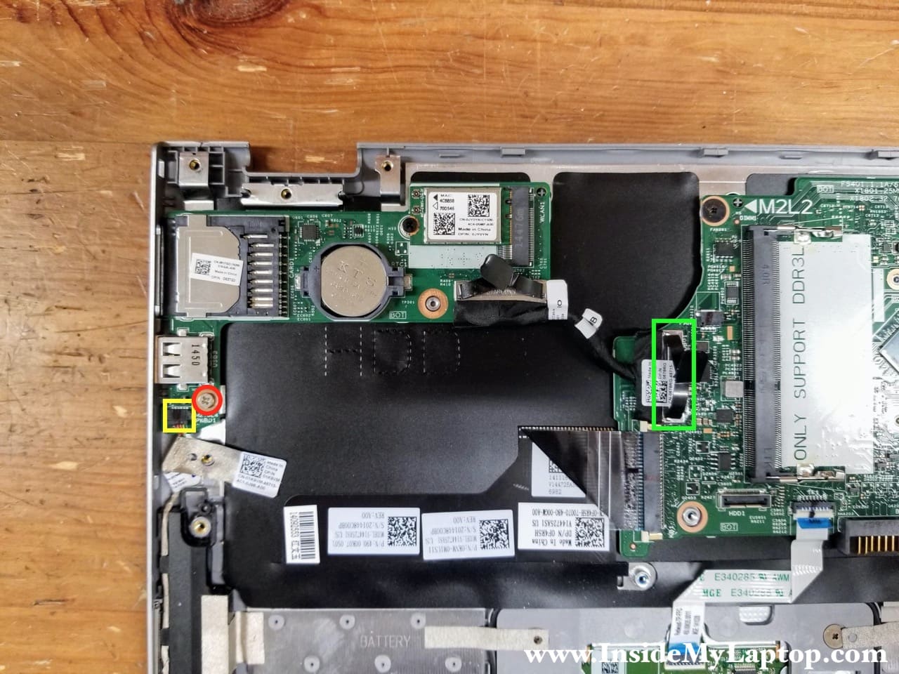
Remove one screw securing the USB/media card reader board.
Disconnect the power button board cable (yellow) from the USB/media card reader board.
Disconnect the I/O cable from the motherboard (green).
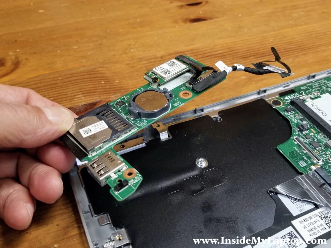
STEP 15.
Lift up and remove the USB/media reader board.
As you see, the BIOS battery is mounted on that board.
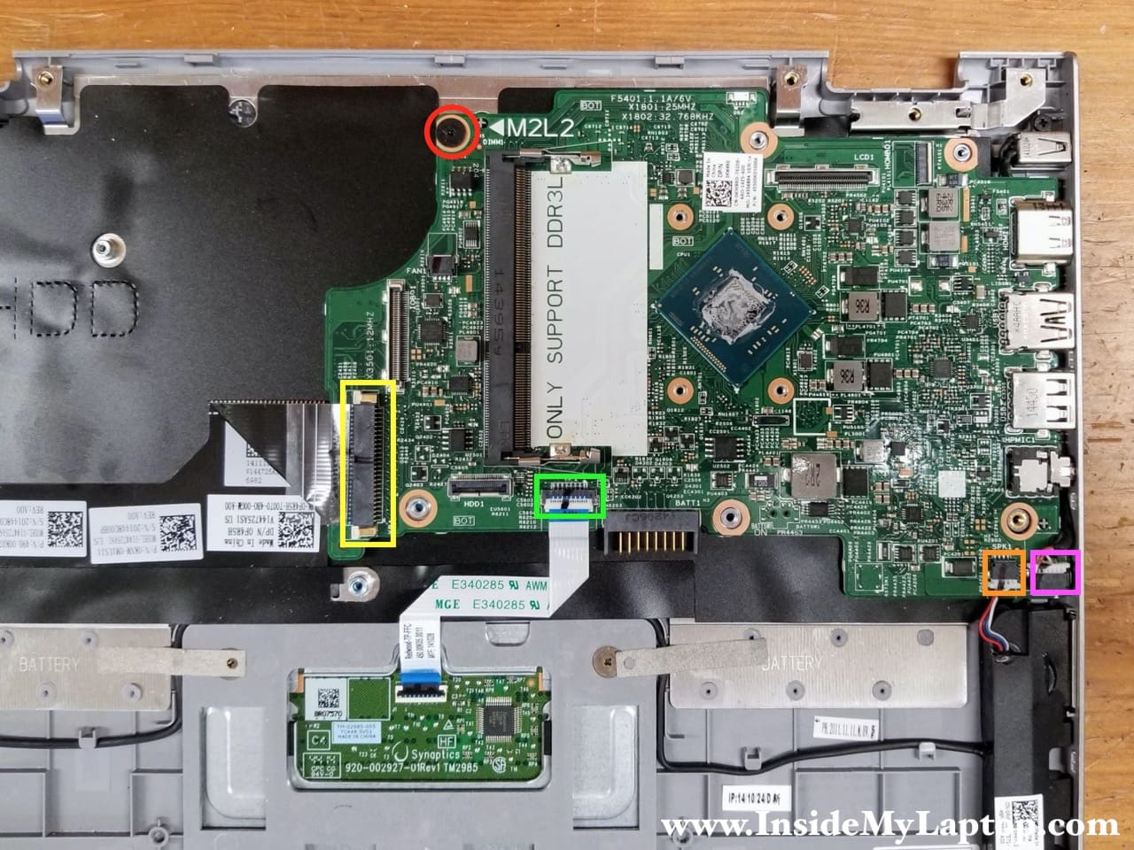
STEP 16.
Remove one screw securing the motherboard.
Disconnect the following color-coded cables:
– Keyboard cable (yellow).
– Touchpad cable (green).
– Speaker cable (orange).
– DC power jack cable (pink).
STEP 17.
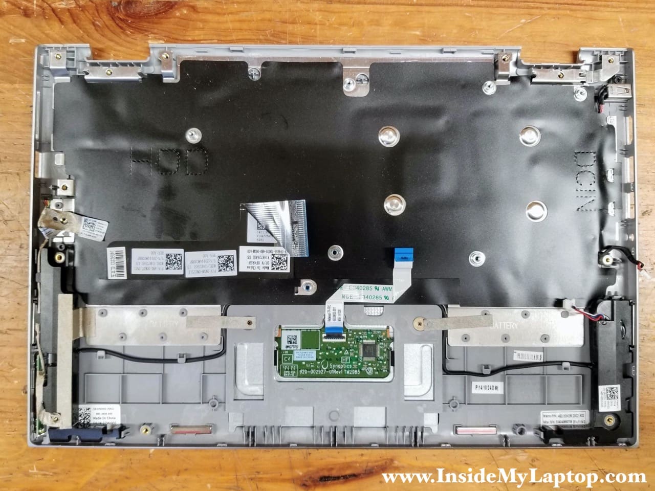
Separate the motherboard from the top case assembly and remove it.
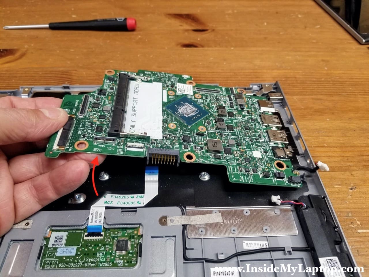
Here’s the other side of the motherboard.

Dell Inspiron 11 3147 3148 2-in-1 has the keyboard permanently attached to the top case. The keyboard replacement is possible but not easy.
If you have a failed keyboard, it’s much easier to replace the entire top case assembly.
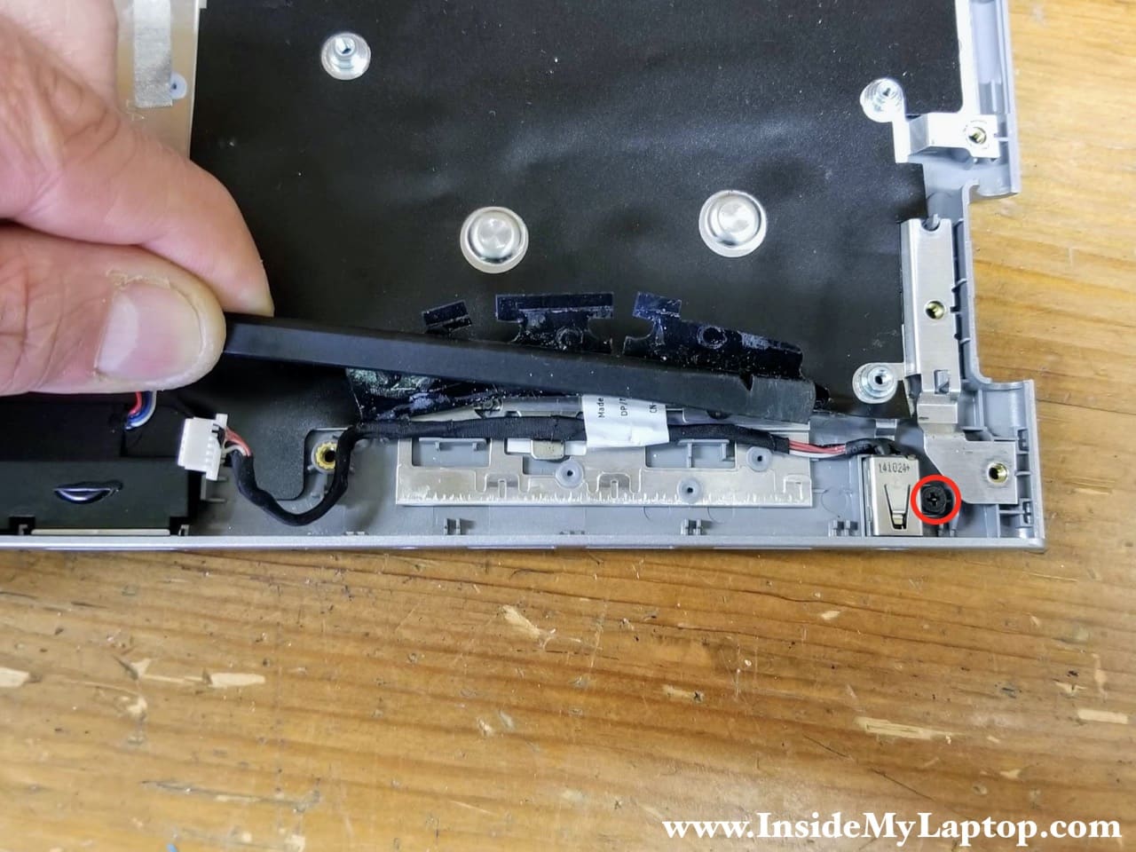
As I mentioned at the beginning of this guide, in order to remove the DC power jack it’s necessary to remove the motherboard first.
STEP 18.
Peel off the mylar cover. Remove one screws securing the DC jack to the case.
Lift up and remove the DC power jack harness.
David McCall
I replaced the new battery and tried to charge it but after 12 hours it remained @51%. Can the battery charging system be bad? If so can it be repaired.
Dell P20T 11-3147 Service tag S/N 7JSD832 Express Serv. Code 16433979950
IML Tech
I would blame the “new” battery first. Was it a genuine Dell battery that you bought or one of those “genuine” batteries from eBay?