In this guide I explain how to disassemble a Lenovo ThinkPad L13 Yoga (Type 20R5) laptop. The disassembly process is relatively simple and shouldn’t take much time.
Lenovo ThinkPad L13 Yoga (Type 20R5) laptop design highlights:
– This laptop supports one PCIe NVMe solid state drive.
– Memory (RAM) is not removable. It’s permanently soldered to the motherboard.
– The cooling fan is attached to the heatsink.
For this disassembly you will need a Phillips screwdriver. Tweezers and case opener tool are optional.
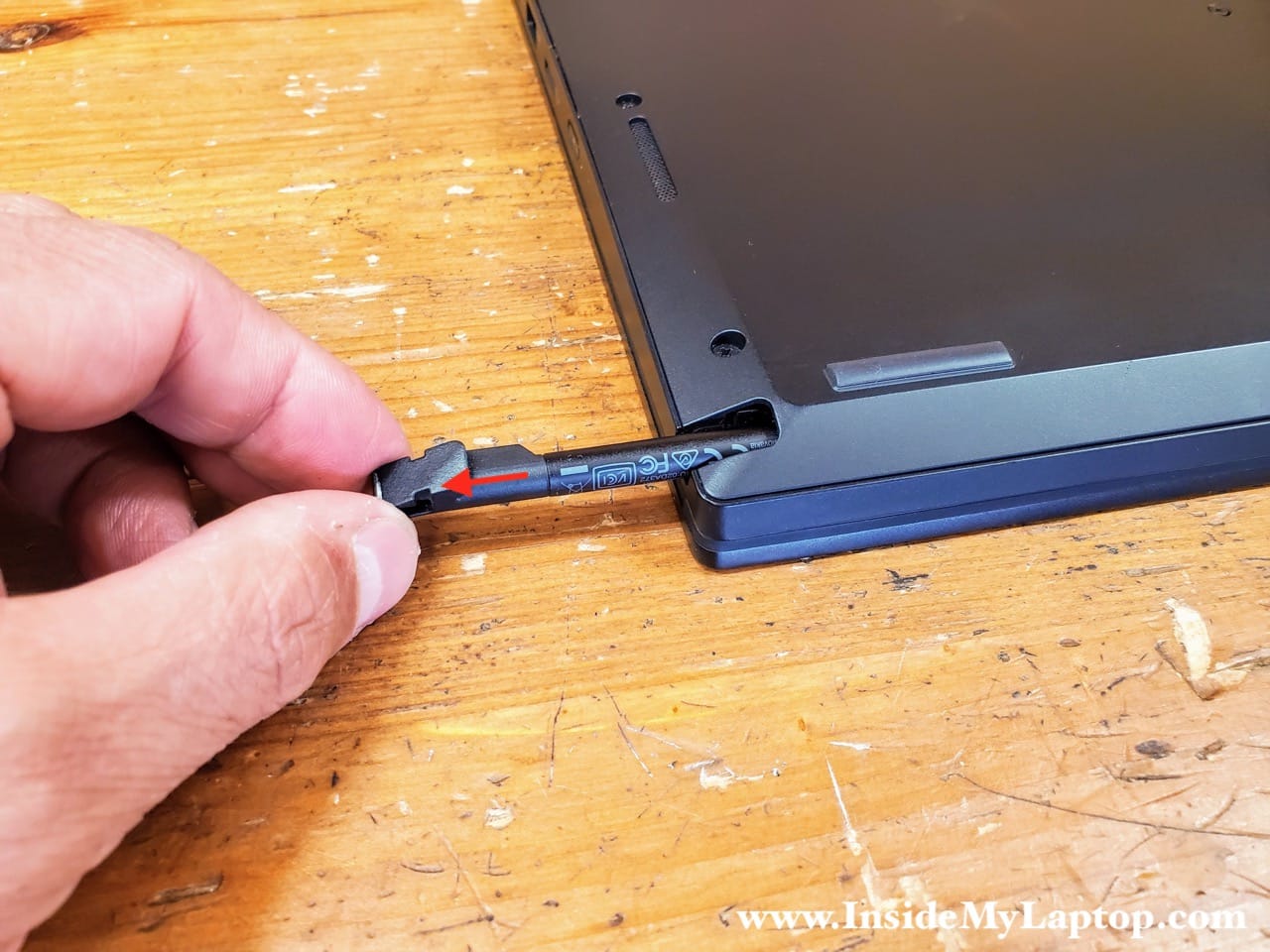
Remove the stylus before removing the bottom cover.
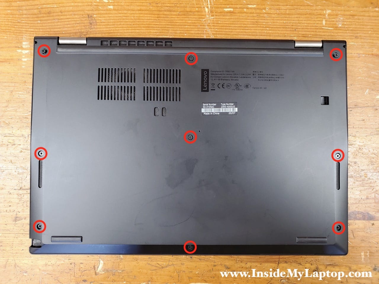
Bottom cover removal
There are nine captive screws that hold the bottom cover in place. Unscrew all screws. They will remain attached to the bottom cover.
Using a plastic case opener tool (or something similar) start separating the bottom cover from the rest of the laptop. You will have to wiggle the bottom cover in order to disengage hidden latches and separate it from the laptop.

Continue lifting up the bottom cover until you can remove it completely.

Battery removal and replacement
There are five screws that hold the battery pack in place. Remove all five screws.
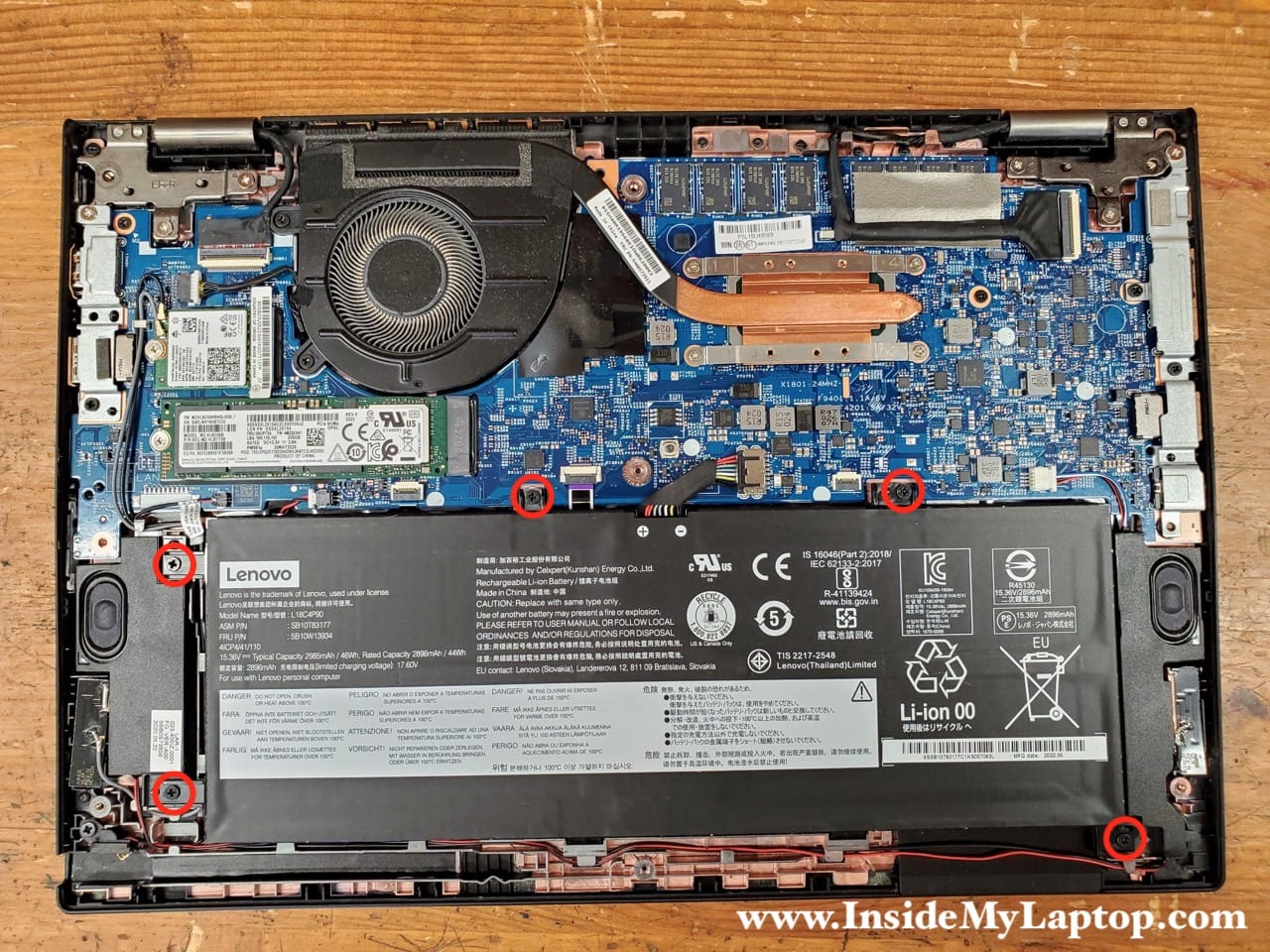
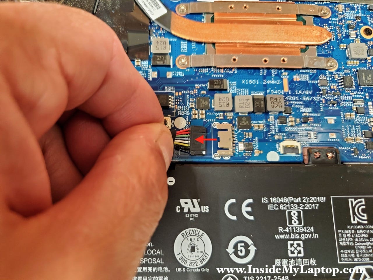
Disconnect the battery cable from the motherboard.
Lift up and remove the battery pack.

If you need to replace the battery, you can find a replacement using the model number L18C4P90 or Lenovo part number 5B10W13934. I strongly advise using genuine Lenovo batteries.

SSD removal and replacement
Lenovo ThinkPad L13 Yoga laptop has only one PCIe slot for NVMe solid state drive (SSD).
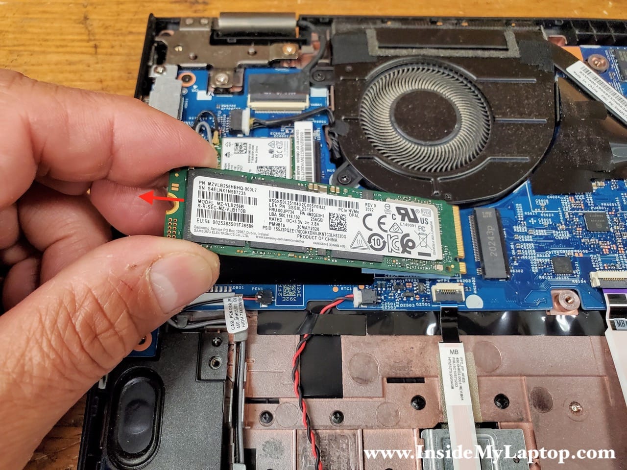
Remove one screw holding the SSD in place.

Pull the SSD out and remove it.
If you need to replace or upgrade the SSD you can use any third party SSD made by Samsung, Crucial, Wester Digital, etc… This is M.2 PCIe NVMe SSD type 2280.
Wireless card removal and replacement
The wireless card is easily accessible and can be removed or replaced if necessary.

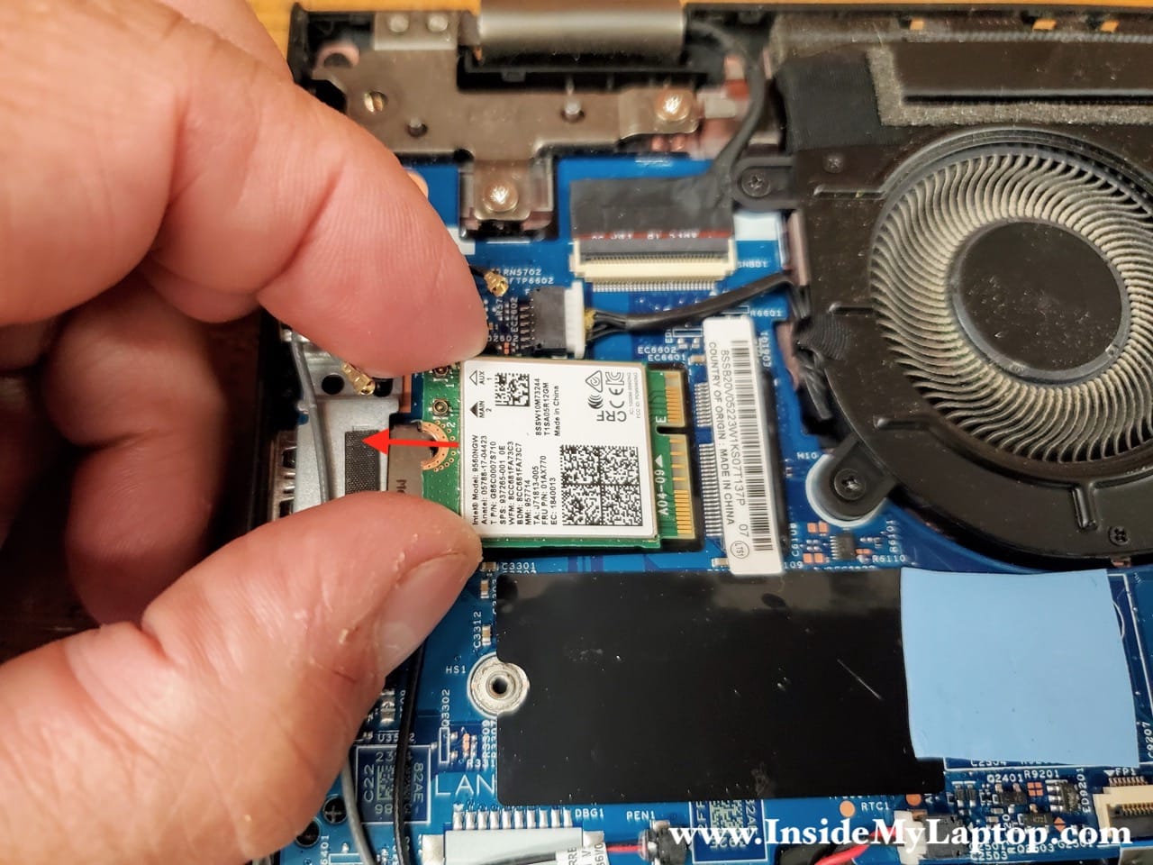
Disconnect two antenna cables from the wireless card. The black antenna cable is attached to the connector #1 and the gray cable to the connector #2. Remove one screw holding the wireless card.

Pull the wireless card out of the slot and remove it.
You can find and replacement wireless card using this Lenovo part number 01AX770. This is Intel 9560NGW Wireless-AC dual band 802.11ac WiFi + Bluetooth 5.0 card.
Cooling fan removal and replacement
In this laptop the cooling fan is attached to the heatsink and they have to be removed together.
Unscrew 6 captive screws holding the cooling assembly in place.
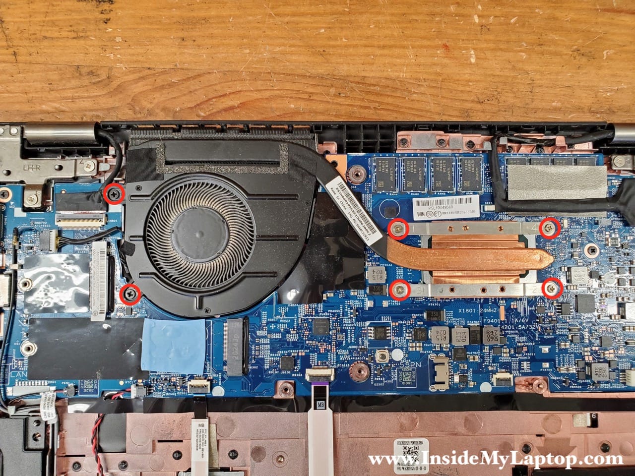
Unplug the cooling fan cable from the motherboard.

Lift up and remove the cooling fan and heatsink assembly.

You can find a new replacement fan if you search the part number 5H40S72913.

Display assembly removal
Remove five screws securing two brackets on the left and right sides of the motherboard.

Lift up and remove the left bracket.

Lift up and remove the right bracket.

Disconnect two display cables from the motherboard.

Here’s how to unlock the connector and release the cable.
Lift up the connector lock so it opens up at a 90 degree angle (red arrow). Lift up and remove the display cable (yellow arrow). Release another cable using the same technique.

Open the display panel 180 degrees and place the laptop on the desk as it shown on the following picture. Remove four screws securing the display hinges.

Now you can separate the display panel from the laptop body.

