
In this guide I show how to disassemble an HP Pavilion x360 14m-ba114dx Convertible PC (2017 model).
You can use this guide for many other models in the HP Pavilion 14m-baXXX x360 computer line: 14m-ba011dx, 14m-ba013dx, 14m-ba014dx, 14m-ba015dx and probably some others.
What I don’t like about this model?
– Both memory slots and the M.2 SSD slot are hidden under the motherboard.
– The display panel can be removed only after the motherboard removal.
– The DC jack bracket also blocked by the motherboard.
– The keyboard is not removable (pretty standard for newer laptops).
Repair tools needed for this disassembly: Phillips screwdriver #1 or #0, tweezers, case opening tool.
Top case and battery removal
STEP 1.
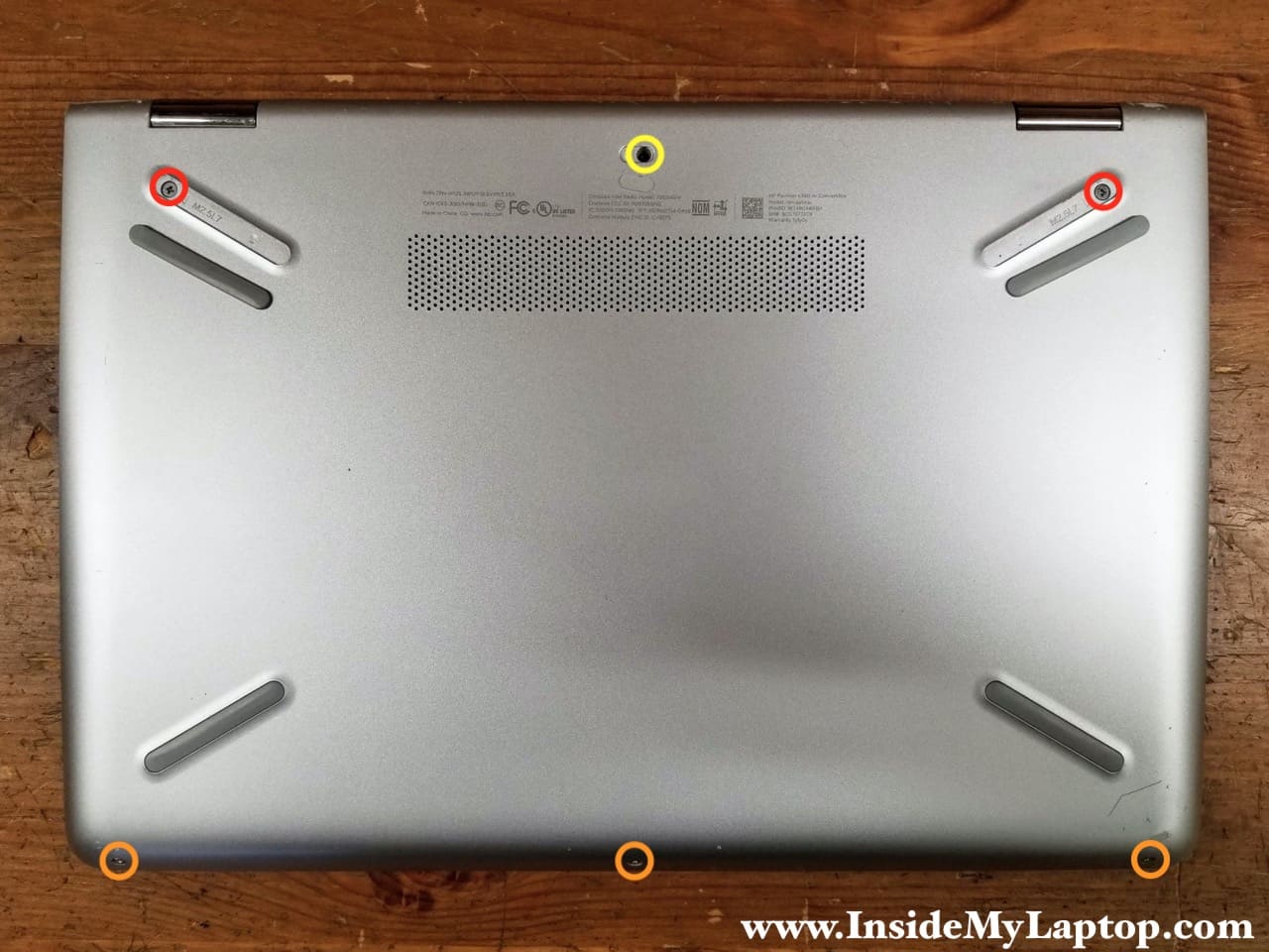
Remove all screws located on the bottom of the laptop. Two screws (red) are hidden under the self-adhesive rear rubber feet. One screw (yellow) is hidden under the self-adhesive seal. All screws are different. Keep track of them.
STEP 2.
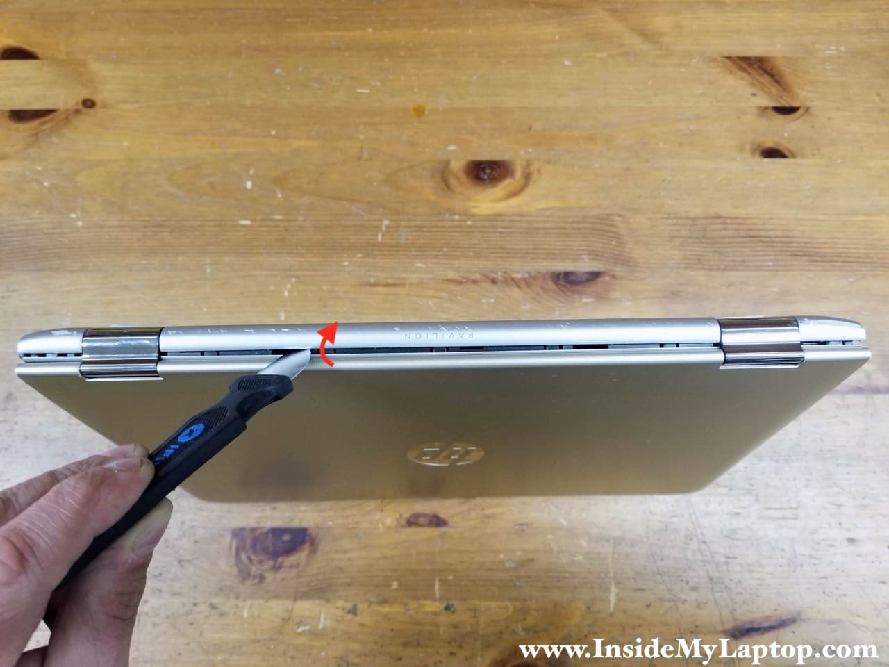
Start separating the base assembly from the top case on the rear side of the laptop. You will need a thin case opener tool for that.
STEP 3.
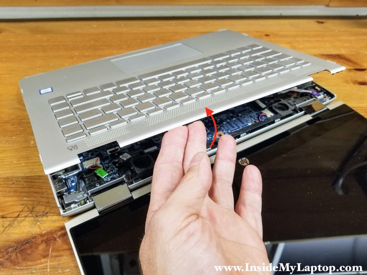
Open the display 180 degrees and continue removing the top cover with your hands. You’ll need to apply some reasonable force to remove the top cover.
STEP 4.
Be careful while lifting up the top cover. The keyboard and touchpad are still attached to the motherboard. You need to disconnect three cables before removing the top case completely.

Here’s how to unlock the connectors and release the cables.
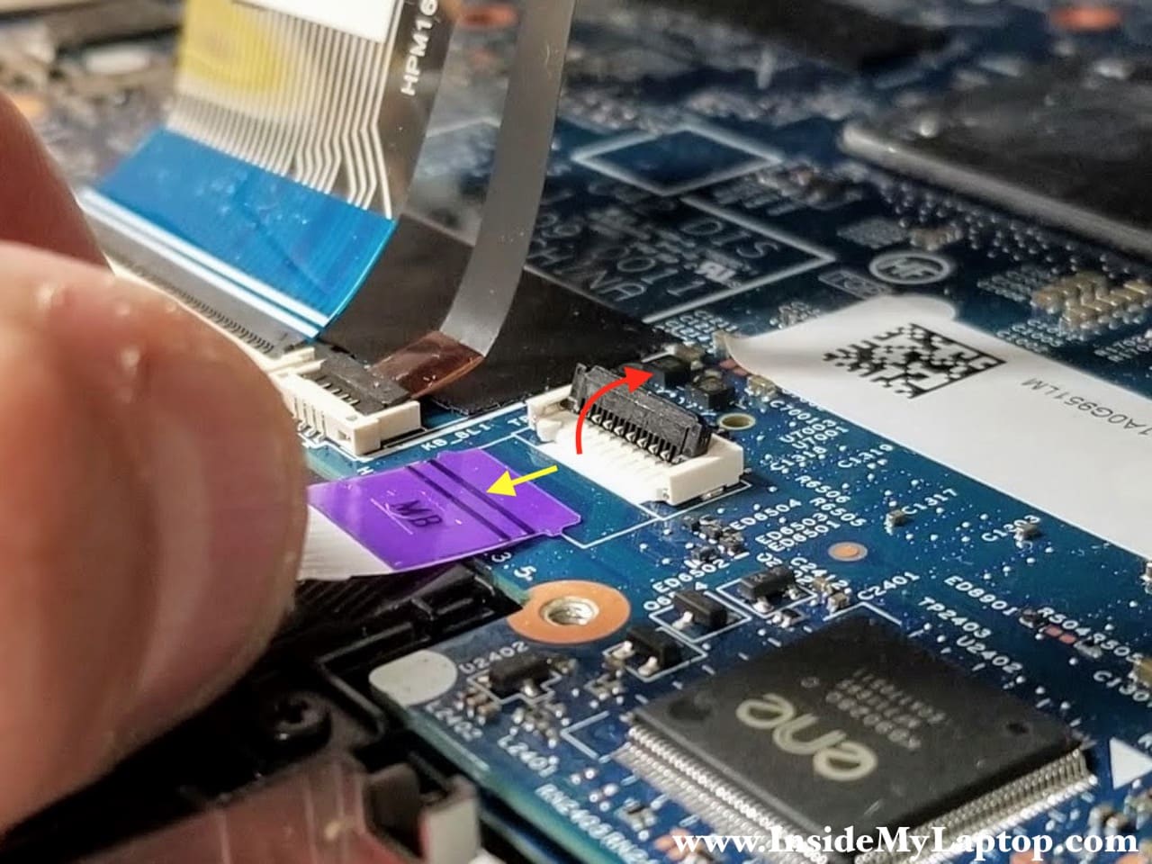
Lift up the locking tab to unlock the connector (red arrow). Lift up the cable and pull it out (yellow arrow).
STEP 5.
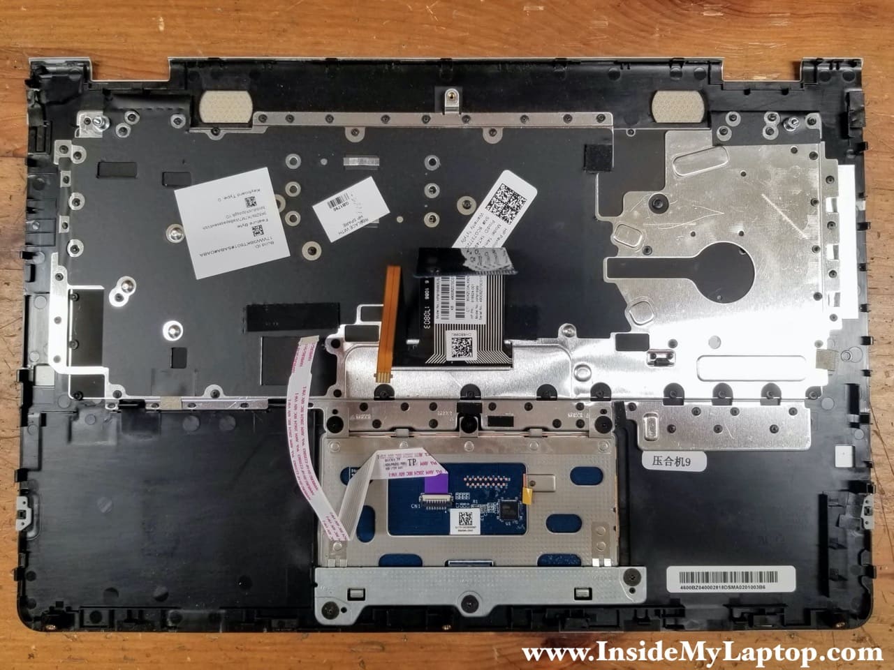
Remove the top case assembly.

On the back side of the top case you can access the touchpad and remove it if necessary (secured by six screws).
HP Pavilion x360 14m-ba114dx keyboard is permanently mounted to the top case and cannot be easily removed. Here’s a DIY hack to replace the keyboard.
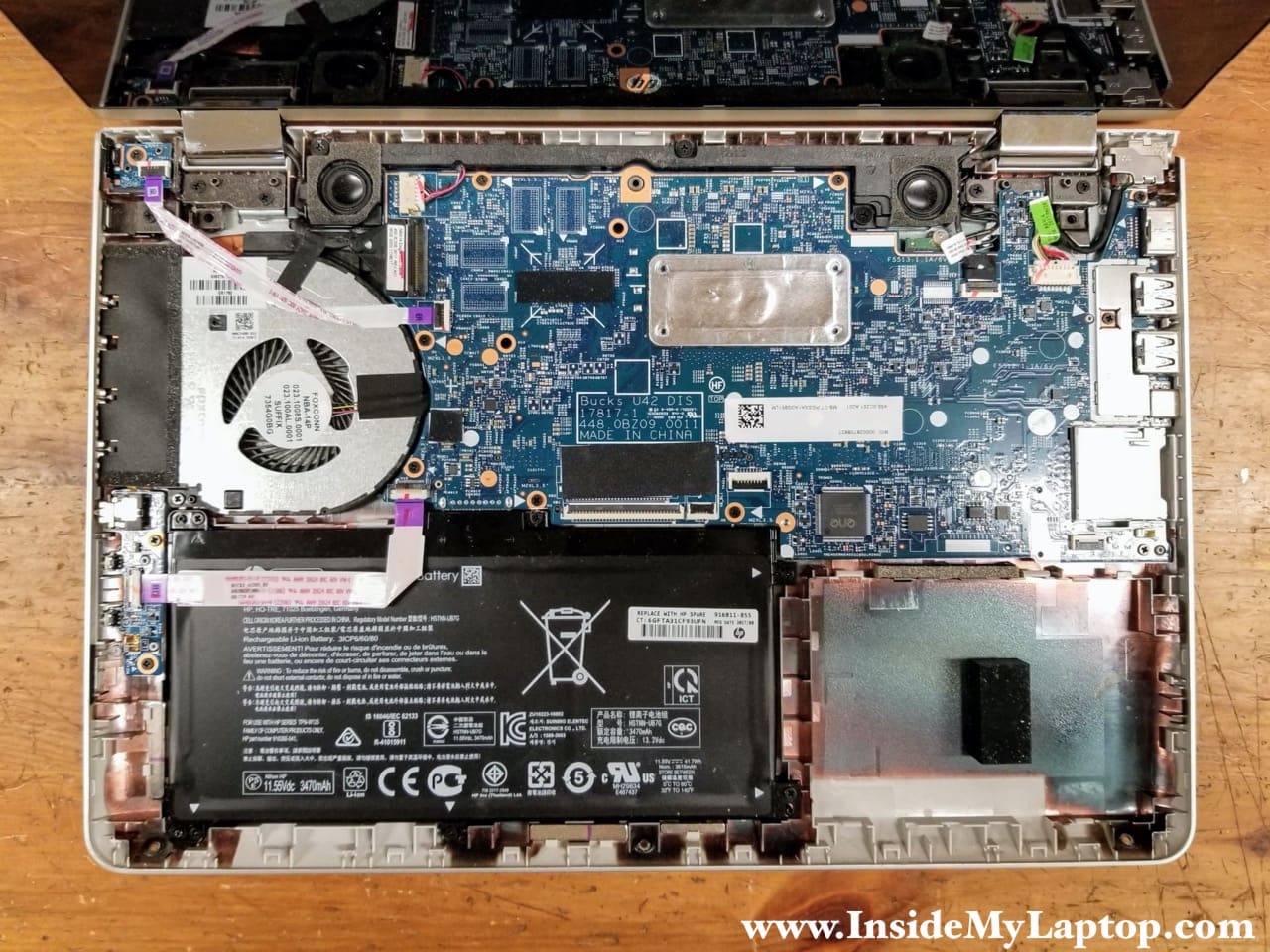
The battery is mounted under the audio jack board cable so we’ll be removing this board.
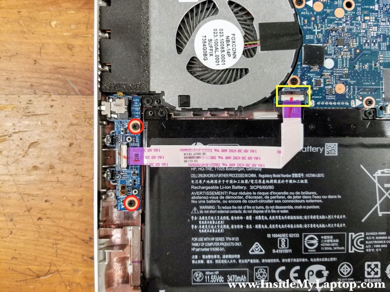
STEP 6.
Remove two screws from the audio jack board. Disconnect the cable from the motherboard.
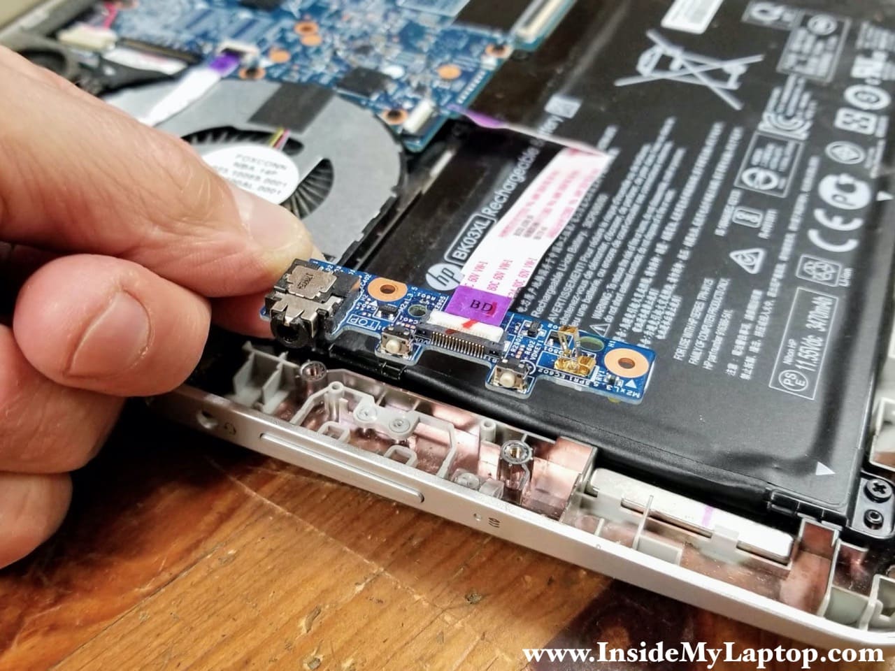
STEP 7.
Lift up and remove the audio jack board with the cable.
STEP 8.
Remove seven screws attaching the battery to the base assembly.
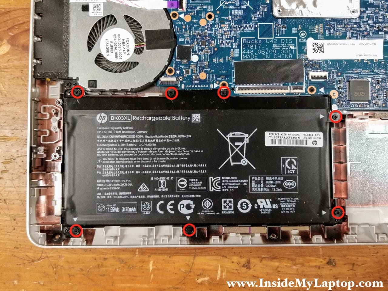
STEP 9.
Lift up the battery to disconnect it from the motherboard and remove the battery.
HP Pavilion x360 14m-ba114dx battery model: BK03XL.

Motherboard removal
STEP 10.
Remove one screw from the power button board and disconnect the cable.
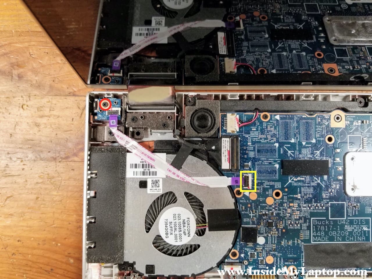
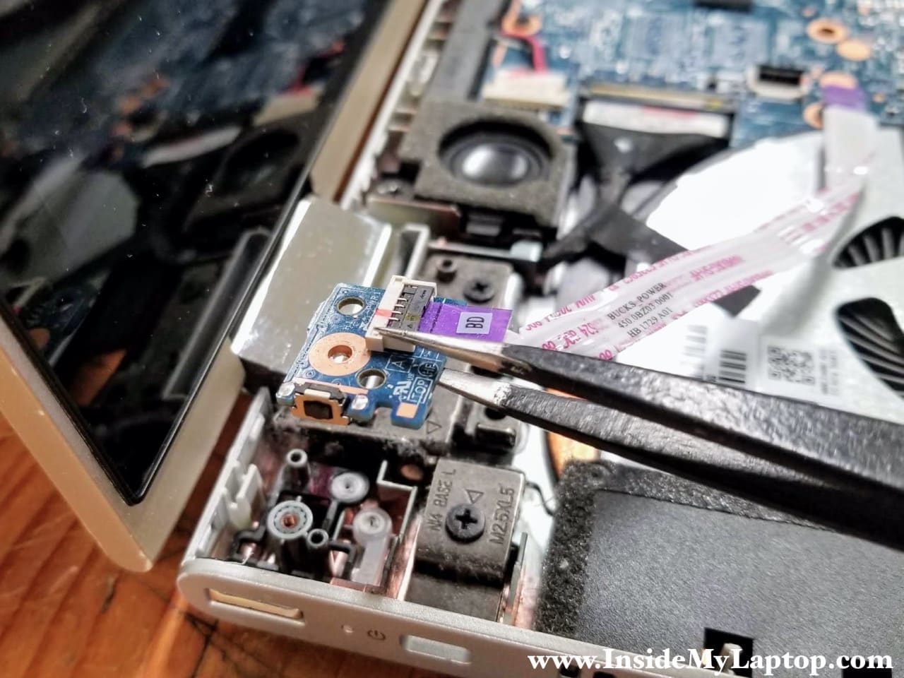
STEP 11.
Lift up and remove the power button board with the cable.
STEP 12.
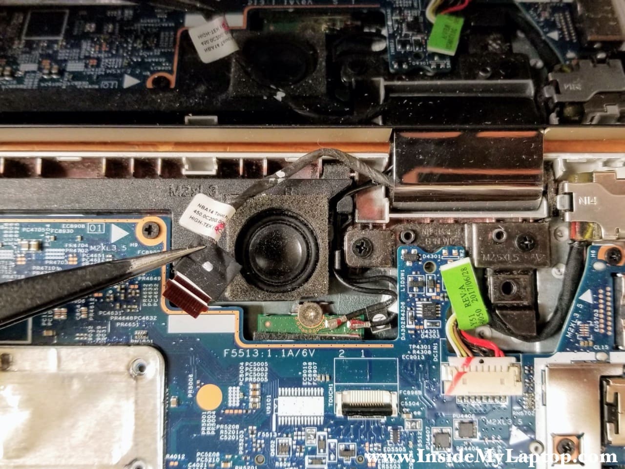
Disconnect the touchscreen cable from the motherboard.
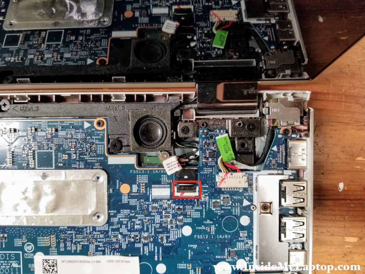
STEP 13.
Un-route the touchscreen cable from the guided path. Now you can access the wireless card antenna cables.
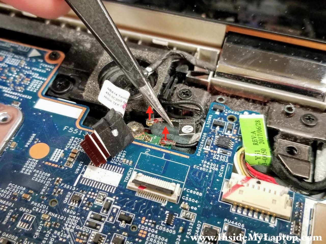
STEP 14.
Disconnect both antenna cables from the wireless card. The cable labeled “M” connected to the port #2. The cable labeled “1” connected to the port #1.
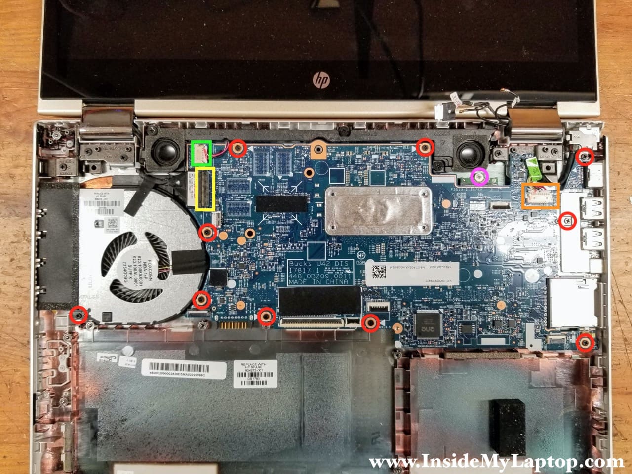
STEP 15.
Remove ten screws securing the motherboard and fan (red). Remove one screw from the wireless card (pink).
Disconnect the following color-coded cables:
– Speaker cable (green).
– Display cable (yellow).
– DC power jack cable (orange).
STEP 16.
Start lifting up the motherboard from the fan side. Remove the motherboard from the base assembly.
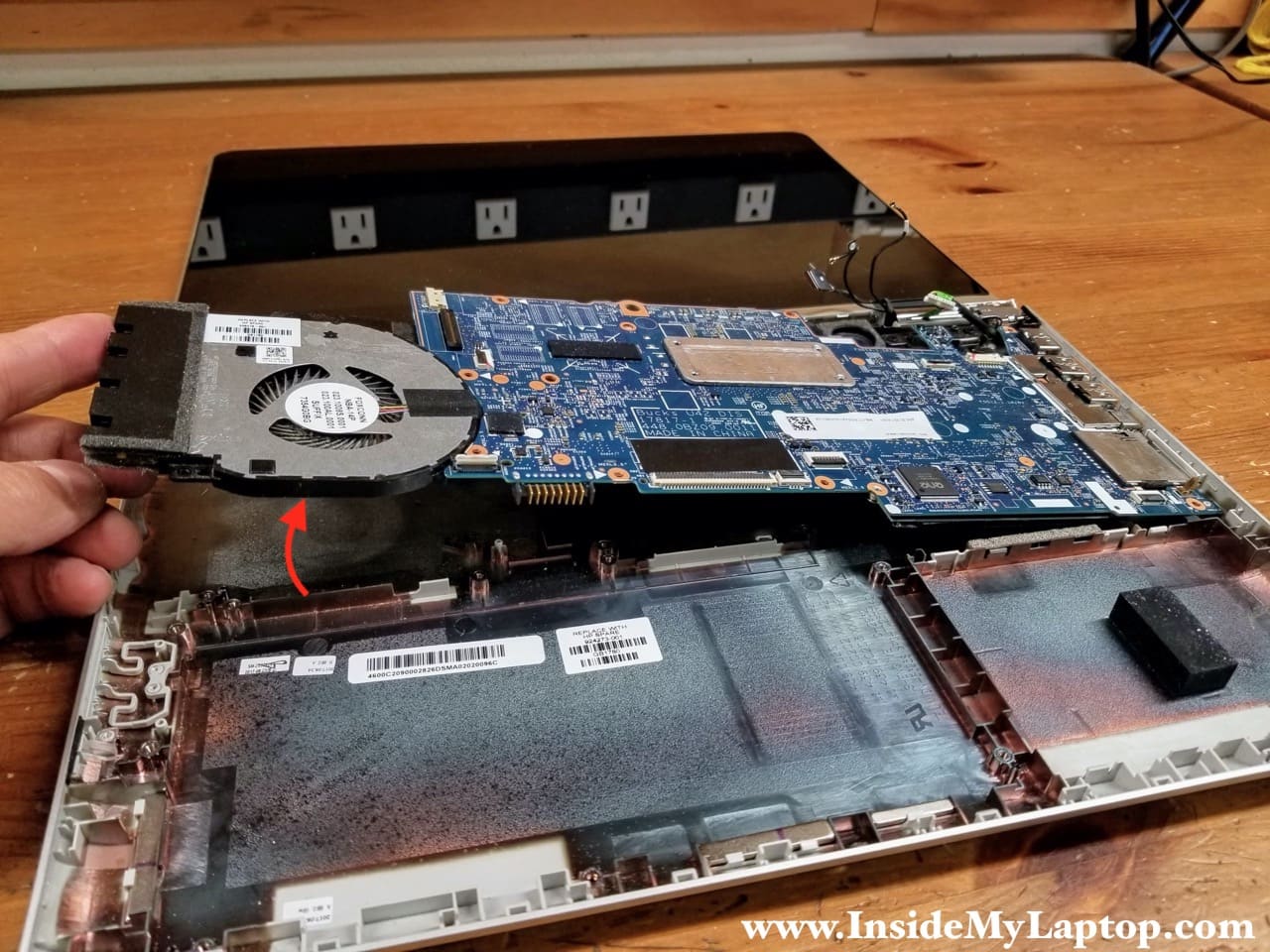
The DC power jack can be removed only after the motherboard removal.
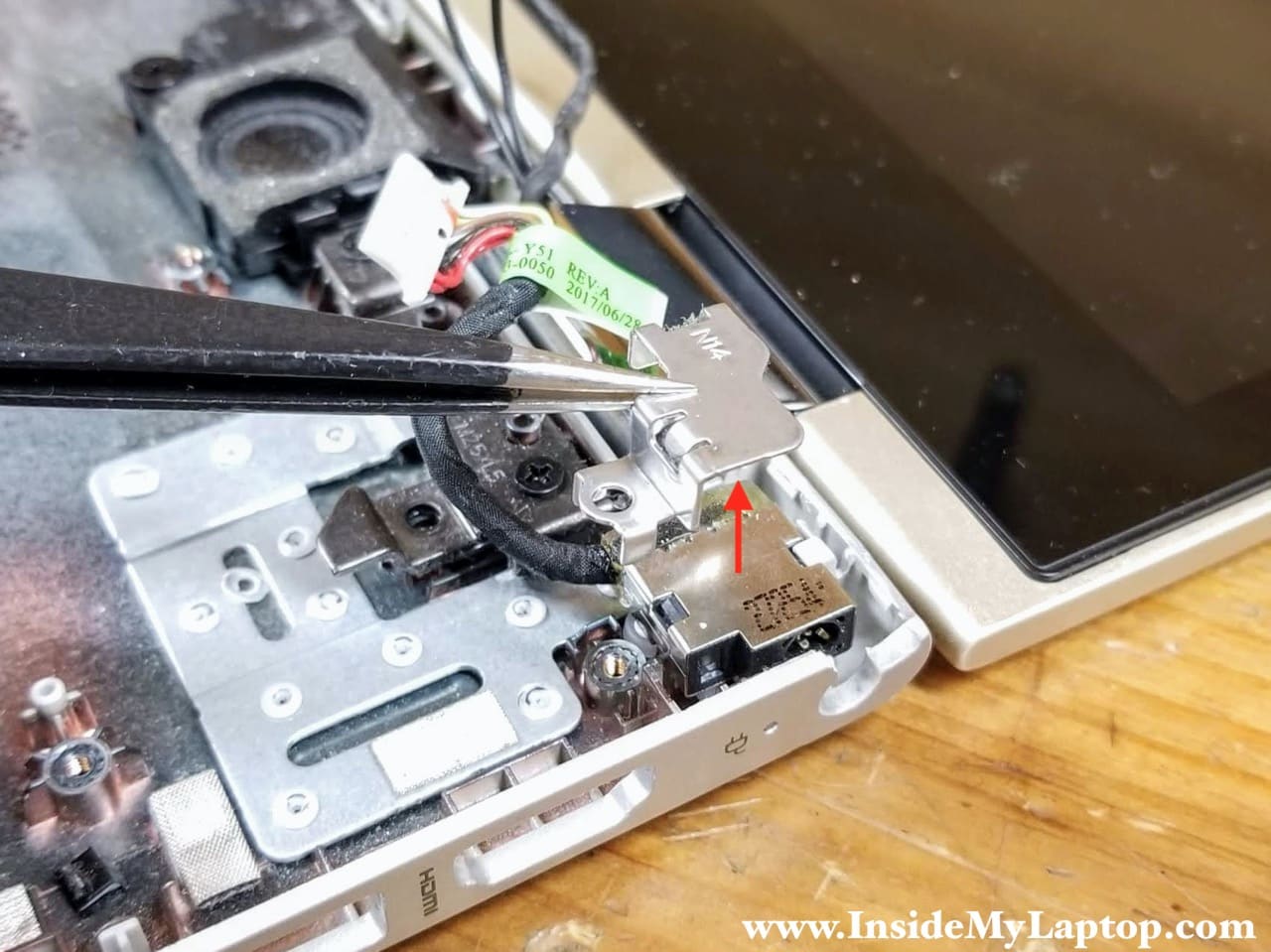
STEP 17.
Remove the DC jack bracket.
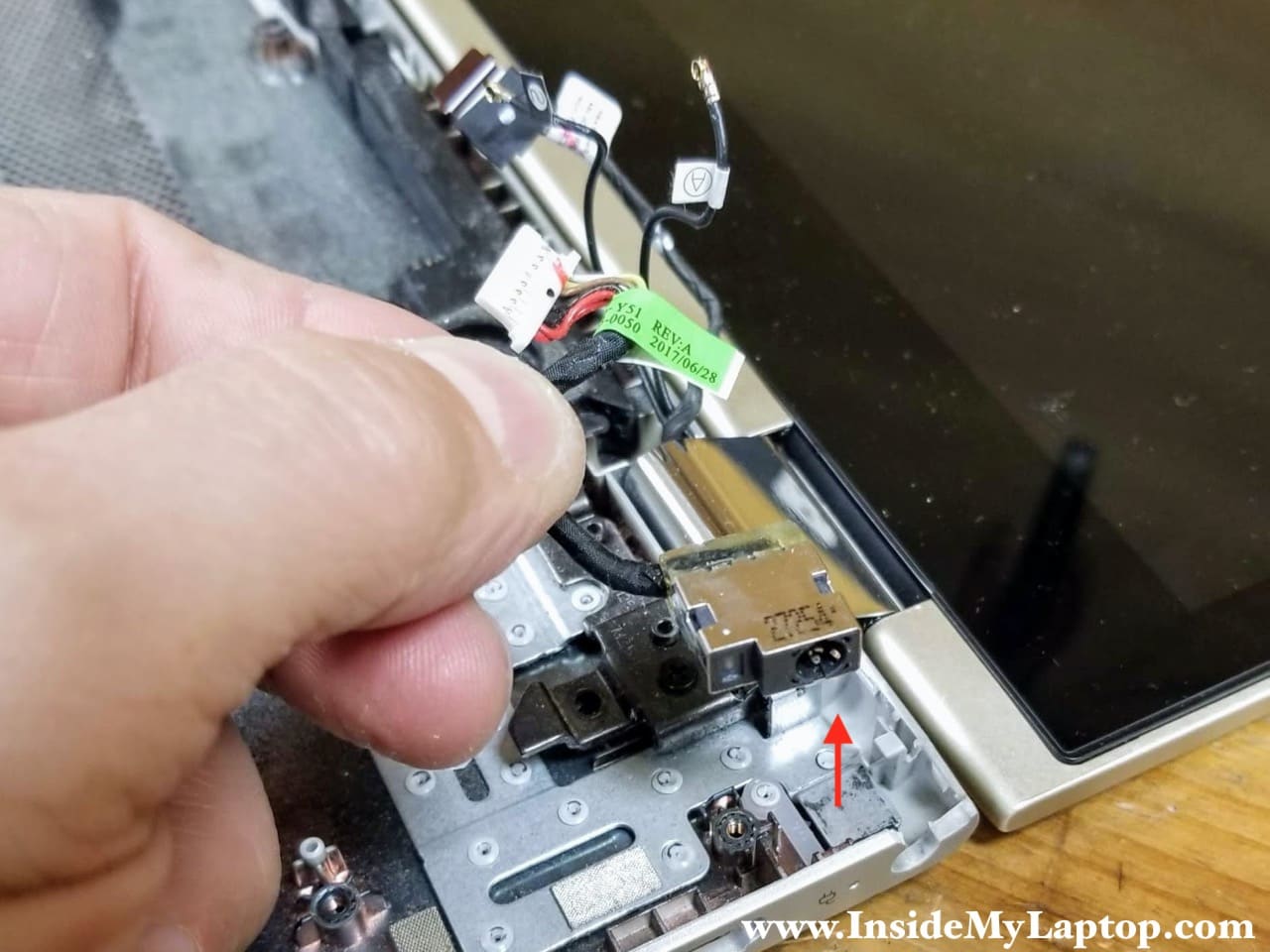
STEP 18.
Lift up and remove the DC jack.
Display panel removal
In order to remove the display panel it’s necessary to remove the motherboard.
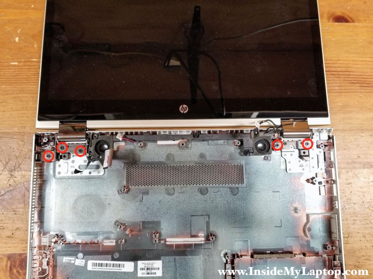
STEP 19.
Open the display 180 degrees. Remove three screws from the left display hinge and two more from the right hinge.
STEP 20.
Lift up the display panel and remove it from the base assembly.
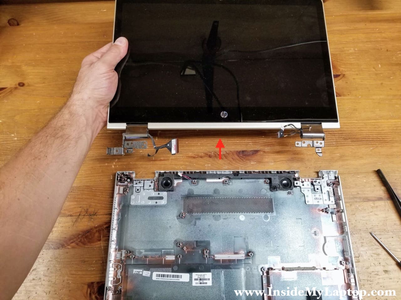
The motherboard has been removed.
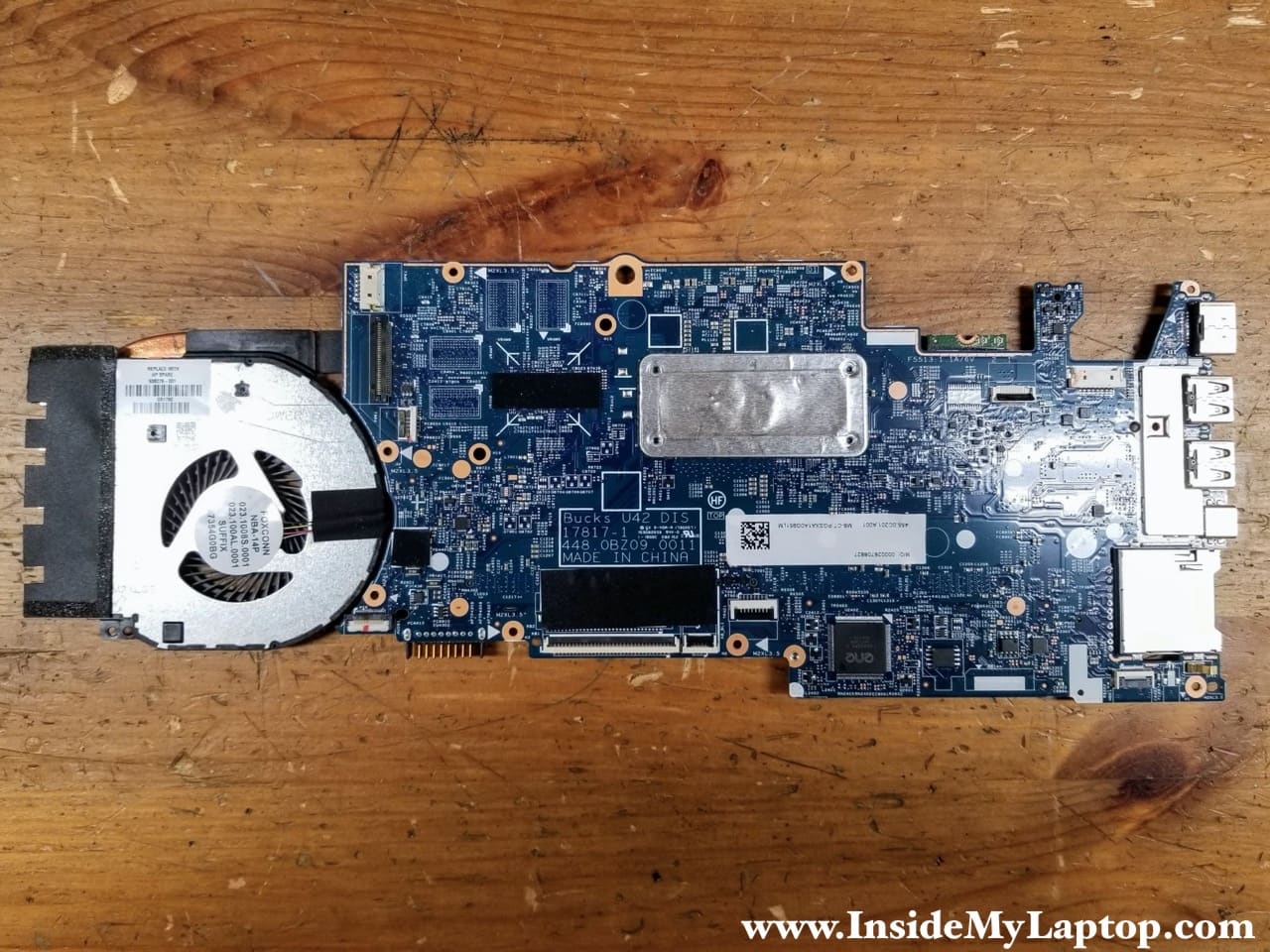
Removing SSD and RAM module
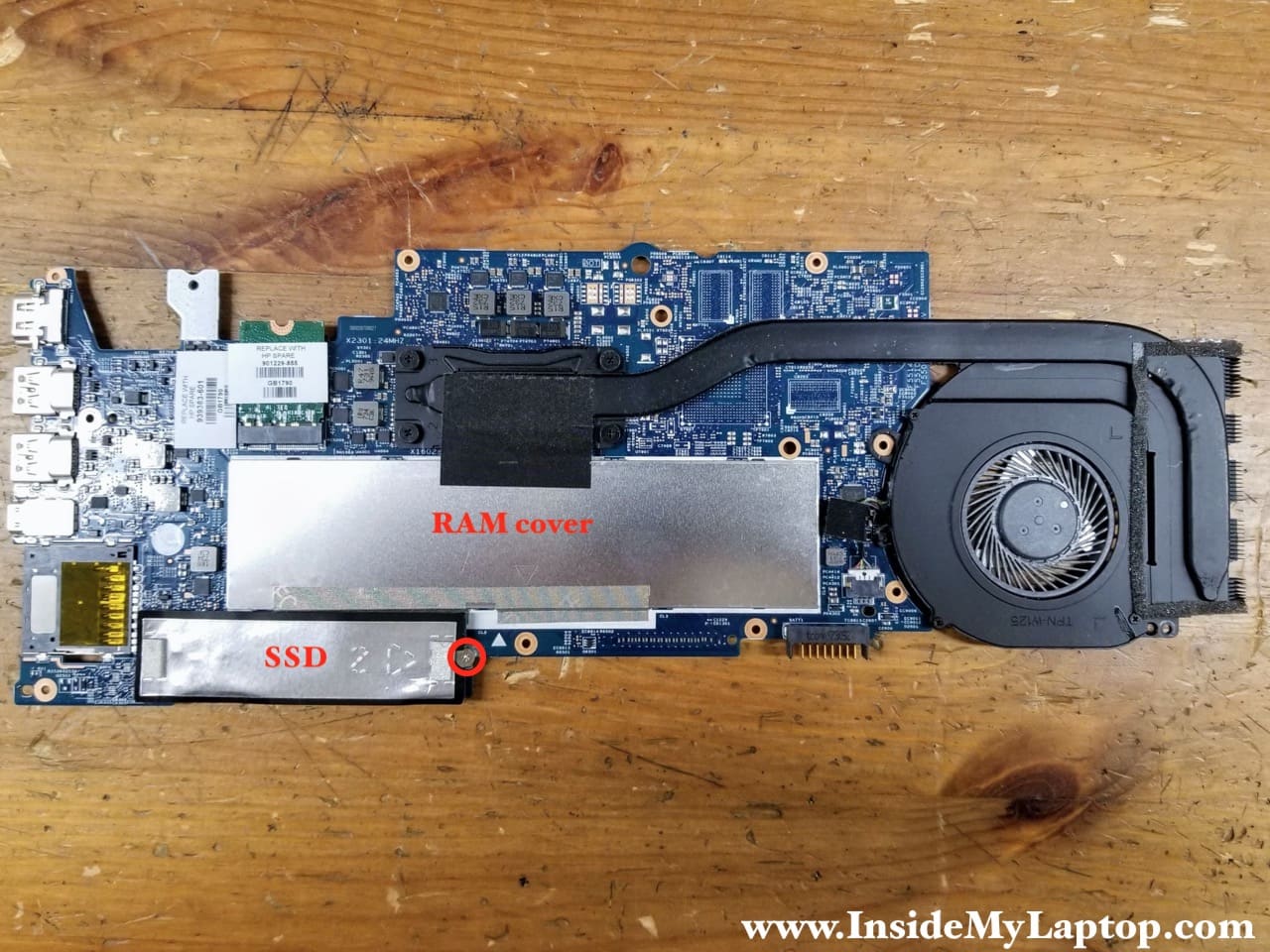
The M.2 SSD and both memory slots can be access on the hidden side of the motherboard.
STEP 21.
Remove one screws securing the SSD.
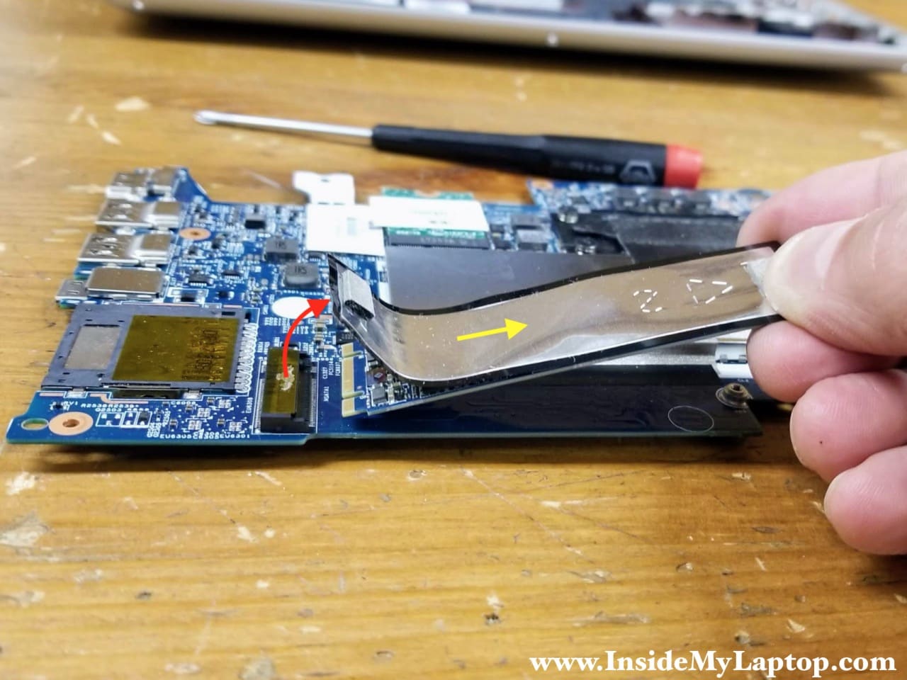
STEP 22.
Peel off the SSD shielding from the M.2 slot (red arrow). Pull the SSD out.
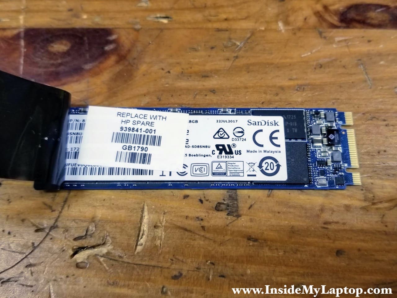
I had a 128GB SanDisk SSD installed (HP spare part number 939841-001).
You can upgrade this drive with a larger capacity SSD.
STEP 23.
Peel off black tape attached to the memory cover.
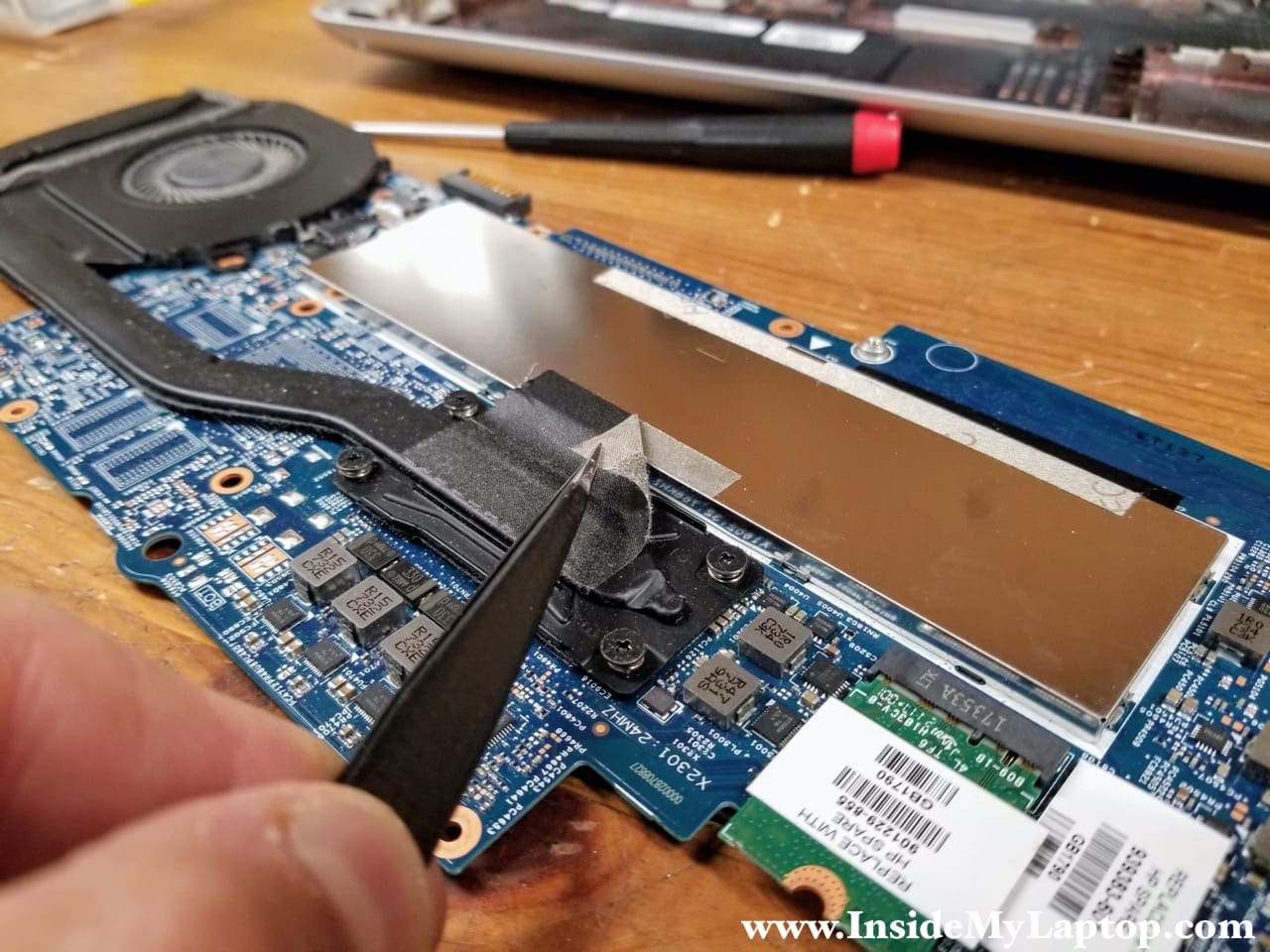
STEP 24.
Start separating the memory cover from the motherboard. The cover is secured by a few clamps located on the motherboard.
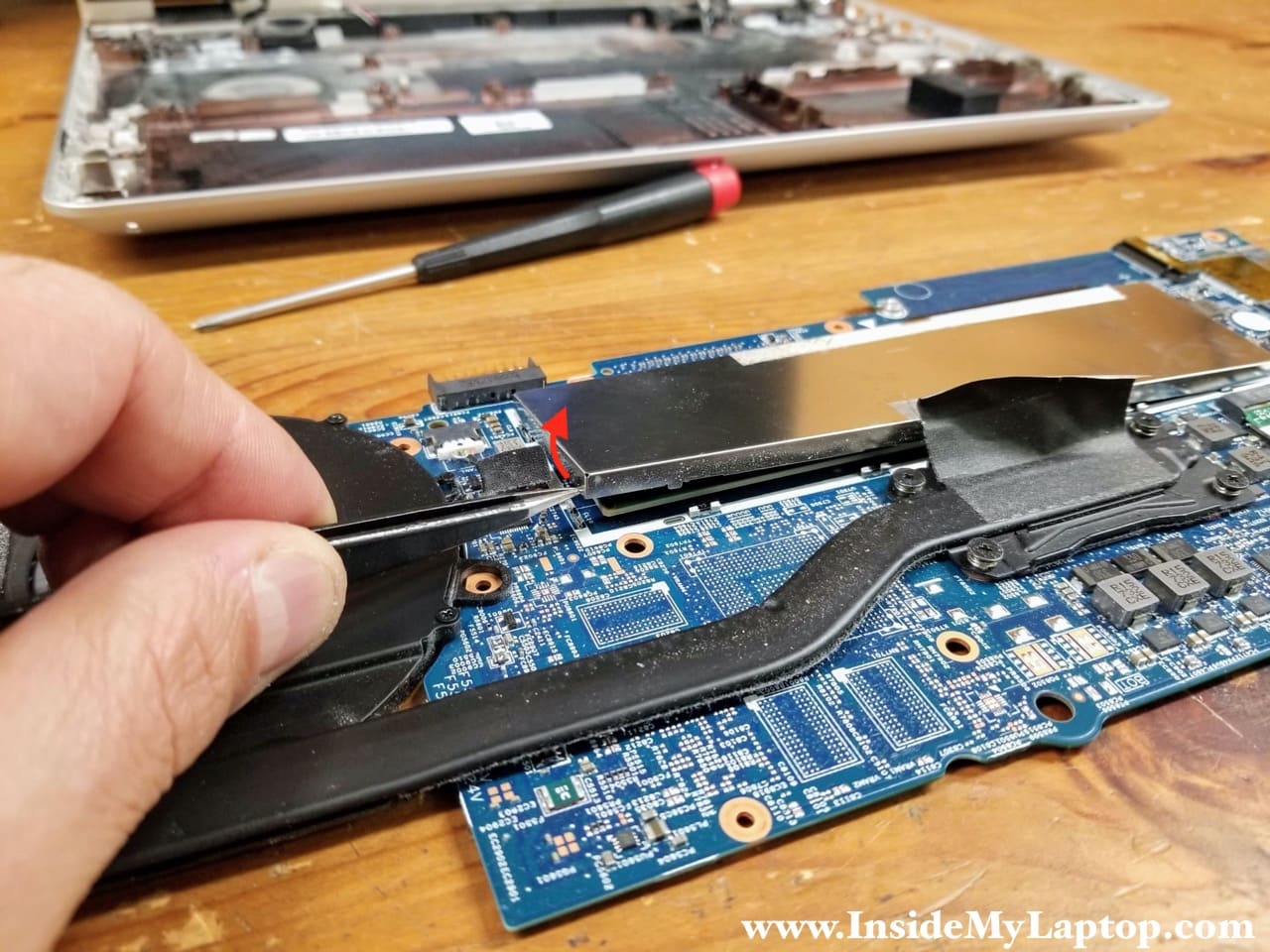
STEP 25.
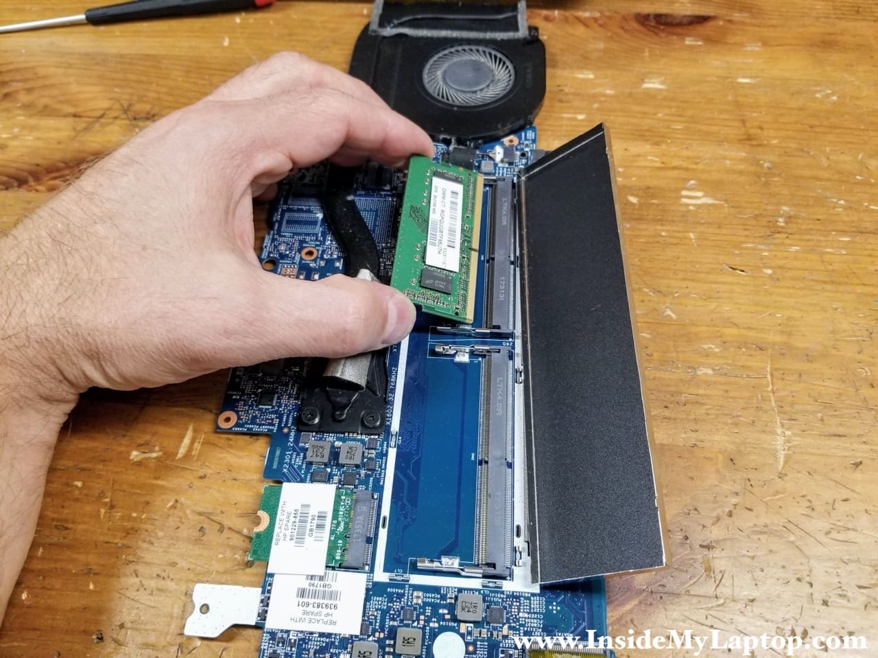
Under the cover you can access two memory slots. I had only one memory module installed.
According to Crucial, HP Pavilion x360 14m-ba114dx can take up to 16GB (2x8GB) DDR4 RAM.
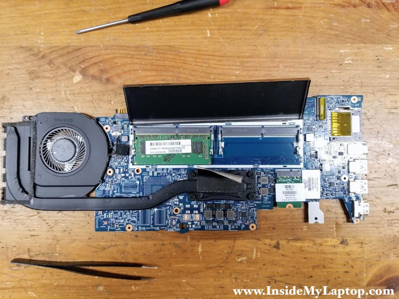
Now you can upgrade laptop memory to the max.
For the next generation (year 2019) models check out my previous HP Pavilion x360 14m-dh1003dx disassembly guide.
Justin Kinberger
Is it possible to install a 2.5″ drive into the laptop? I see that there is a space for it and I believe that it is just missing a ribbon cable, do you happen to know the part number?
IML Tech
Justin, this laptop supports 2.5″ hard drives and it’s possible to install it. Just make sure to install a 2.5″ solid state drive, not a regular slow spinning 2.5″ drive.
For mounting the 2.5″ drive you will need a rubber sleeve. It will secure the hard drive in place. The rubber sleeve part number is: 924283-001. Though I think the rubber sleeve is optional if you can figure out another way to secure the drive, maybe adhesive tape will work well too
HP manual doesn’t mention the part number for the cable which connects the drive to the motherboard. It’s possible the cable comes with the rubber sleeve. Maybe not.
I did some research and it looks like the hard drive cable part number is: 450.0BZ05.0001
The cable available here: https://amzn.to/2QVWszf
Luis Carreño
Hi, I have a Pavillion x360 m convertible mod: 14m-ba114 dx. A bad batery burned or shorted these two components: PU4406 and PU4407. They are just below the white connector located at the top right corner of the motherboard. I neglected to replace the battery going bad when I could, and now the battery died taking with it at least these two components.
What information do you have about PU4406 and PU4407? How can I get a diagram of the MB? Where can I get a new or refurb MB?
Thanks for shareing of your time and knowledge.
deerke
They are N-channel & P-channel mosfets. Just read the numbers on the chips self….They are totaly different from the PU number. the PU is only the boardnumber of the part.
It looks like the 4407 = AON7403 p-channel.
Probably 4406 = n-channel = AON7408= 6V7259
look at ordering always to the desciption 3 x 3 which means 3×3 mm square.
If the get extremely warm it is not garanteed that they are faulty. There can also be a short circuit behind them…..