
In this tutorial I show how to disassemble an Asus VivoBook 15 F512 or X512 laptop. This disassembly guide should work for one of the following Asus VivoBook 15 models: F512DA, F512FA, X512F, X512DA, X512DK, X512FA, X512FB, X512FL, X512FJ, X512UA, X512UB, X512UF and probably some other models too.
Here are some Asus VivoBook 15 F512 X512 design highlights:
– The laptop can support two storage drives: 2.5″ SATA drive and M.2 SATA SSD.
– There is only one RAM slot available for upgrades.
– The cooling fan easily removable.
– The DC power jack soldered to the motherboard.
– The keyboard permanently attached to the top case.
For this disassembly you will need only three basic tools: Phillips #1 screwdriver, case opener tool and tweezers.
Removing the base cover
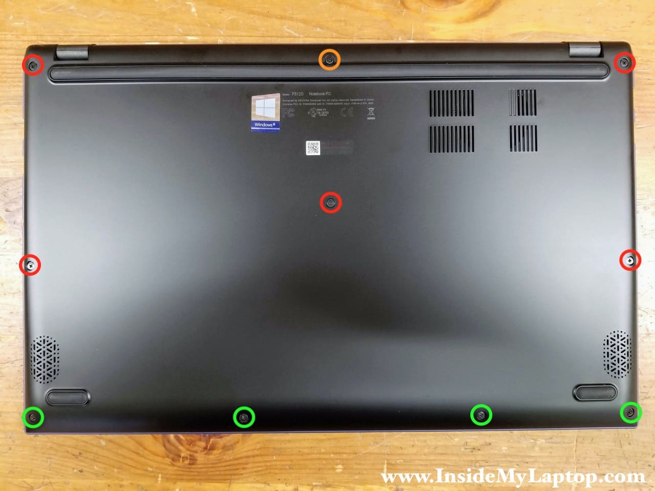
STEP 1.
Remove ten screws securing the base cover. There are three types of screws: orange – the longest screw, red – medium length screws, green – short screws.
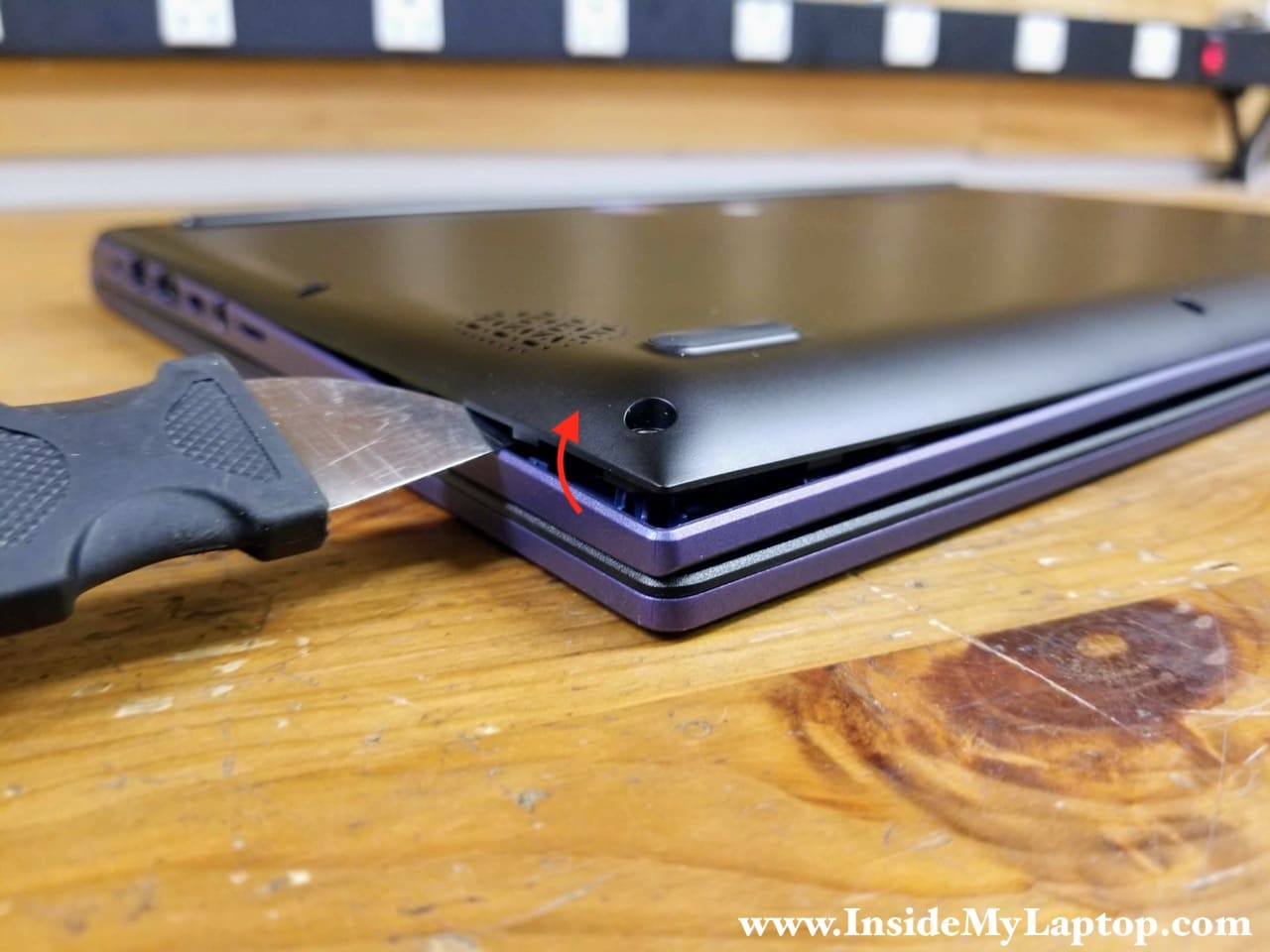
STEP 2.
Pry up the base cover and start separating it from the top case assembly.
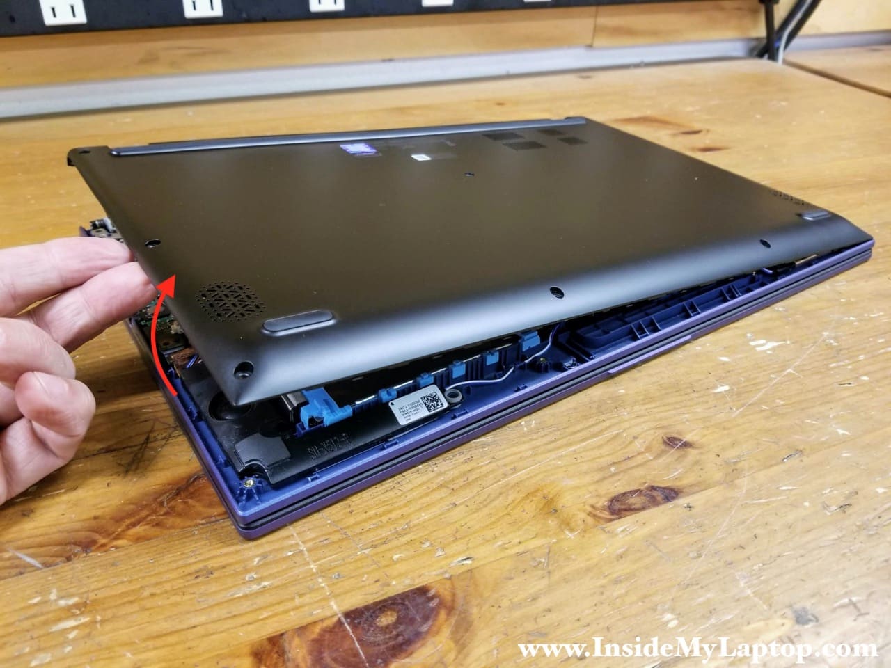
STEP 3.
Continue removing the base cover with your hands. You’ll have to apply some reasonable force to remove the cover. There are multiple hidden latches attaching it to the top case.
Disconnecting and removing the battery
STEP 4.
Remove four screws securing the battery and the battery mounting bracket. Remove the bracket.
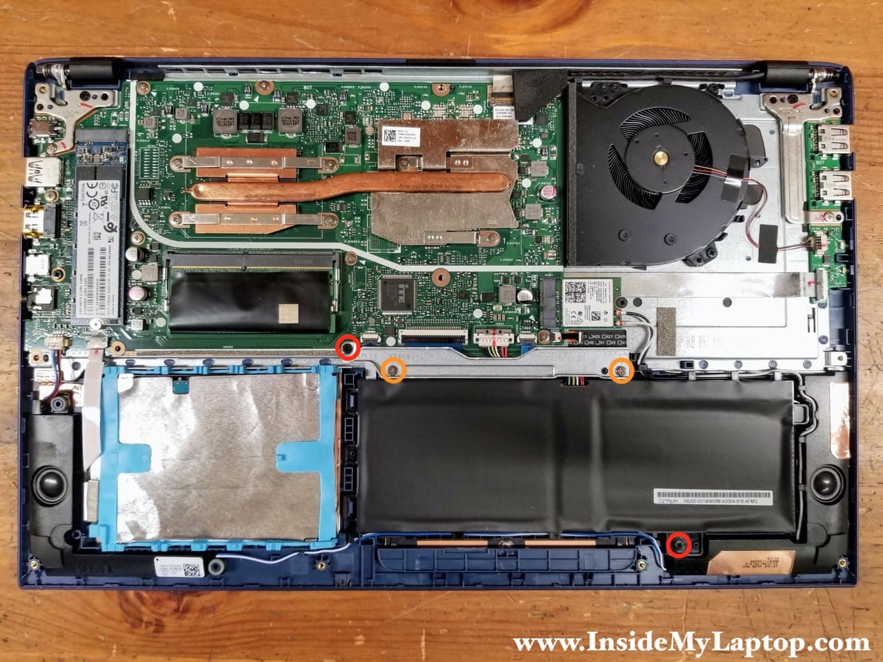
The battery cable is routed under the touchpad cable which has to be disconnected first.
STEP 5.
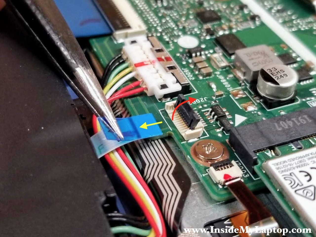
Disconnect the touchpad cable from the motherboard.
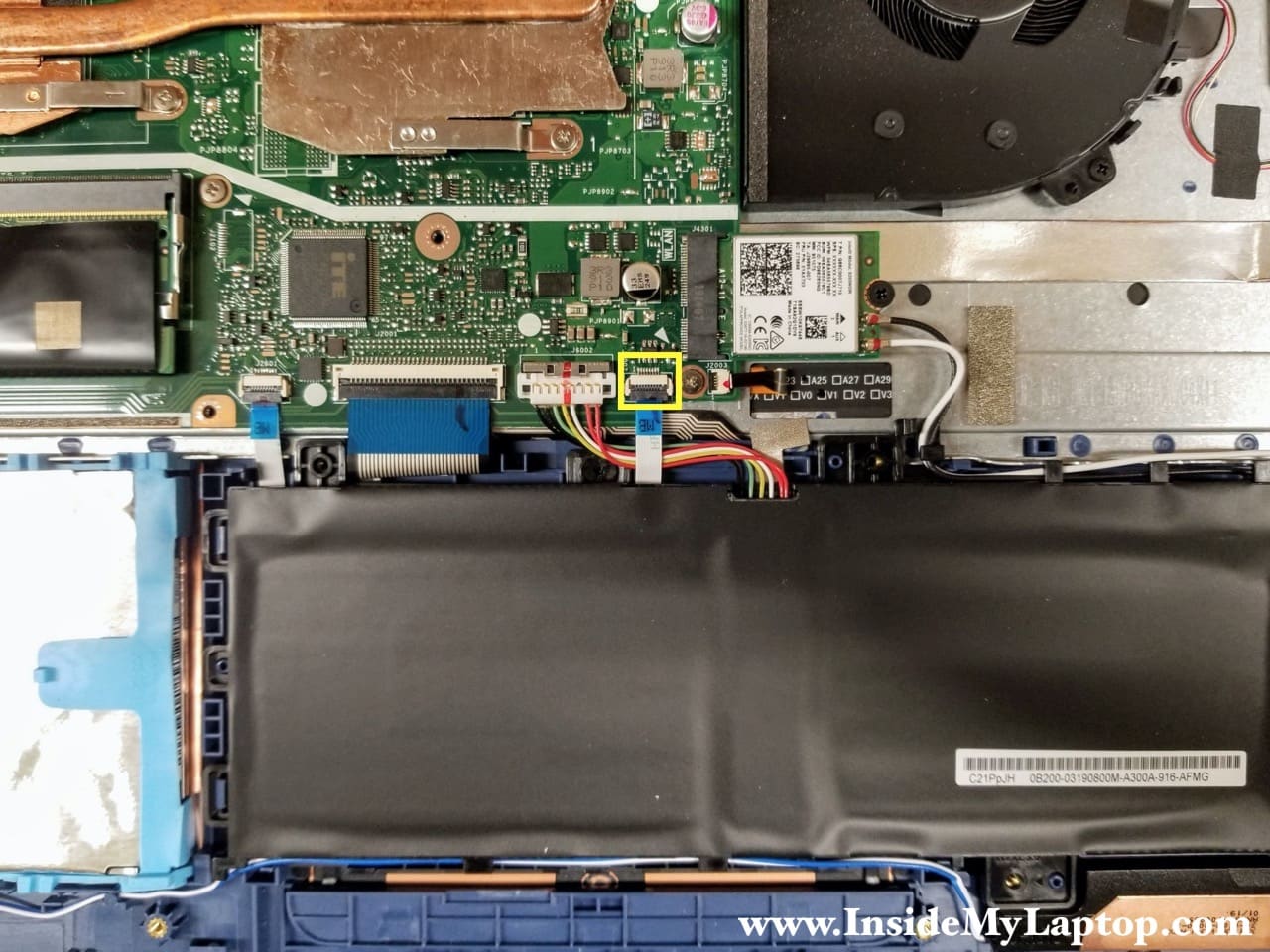
The connector has to be unlocked before removing the cable. Lift up the locking tab (red arrow) to unlock the connector.
STEP 6.
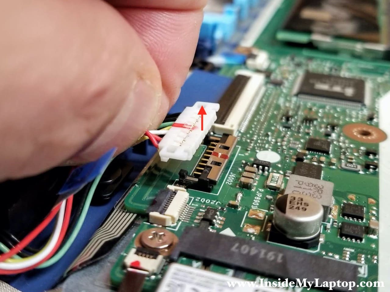
Unlock the battery cable connector and disconnect the battery cable from the motherboard.
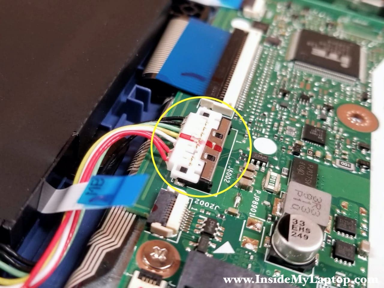
Slide the metal clip to the shown direction (yellow arrow). This clip covers the battery cable to secure the connection.
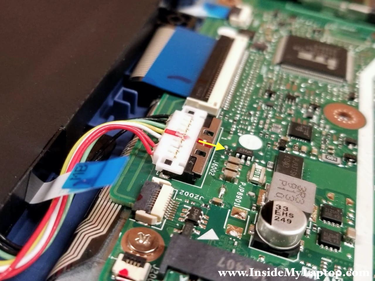
Now you can lift up the battery cable and unplug it from the motherboard. Do not use metal tools to lift up the connector. You can accidentally short the pins and damage the battery or the motherboard. Use your fingernails instead.
STEP 7.
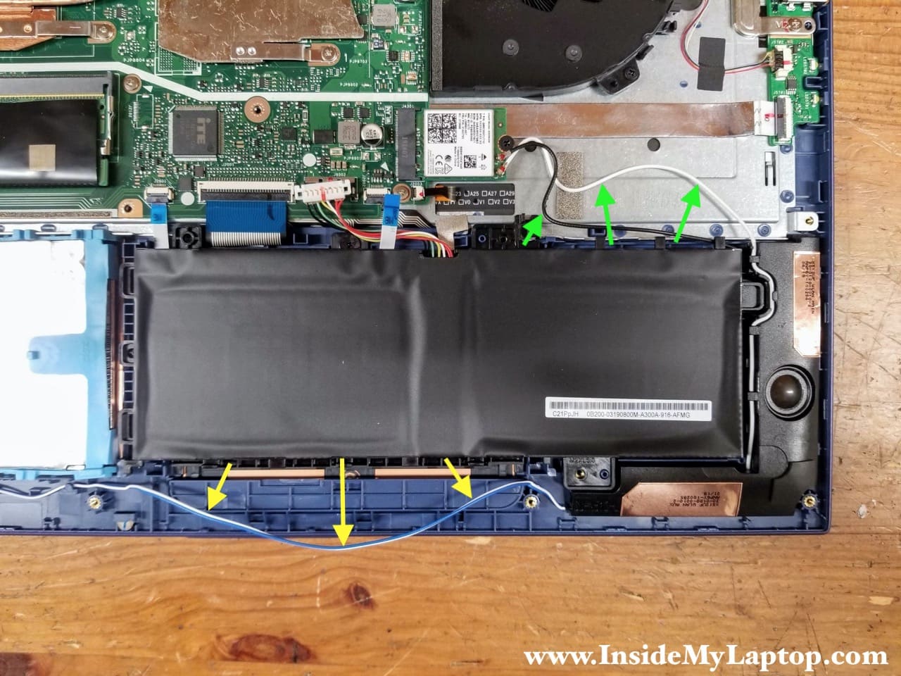
The speaker cables and the Wi-Fi antenna cables are routed in the guided path on the side of the battery. Separate all cables from the battery.
STEP 8.
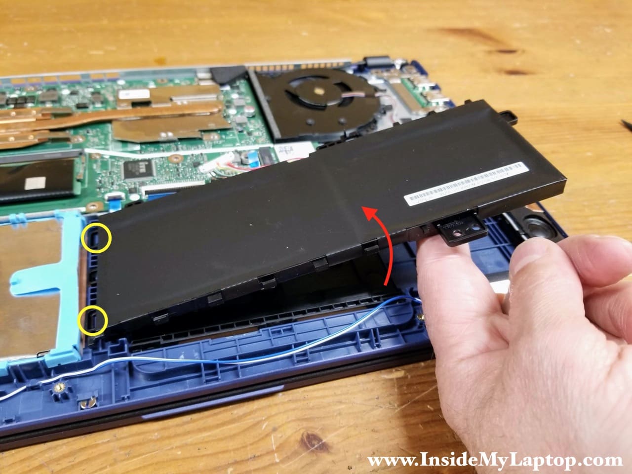
Lift up the battery and remove it from the top case. The battery hinges on two knobs on the left side. Make sure to put it back in place properly during the re-assembly process.
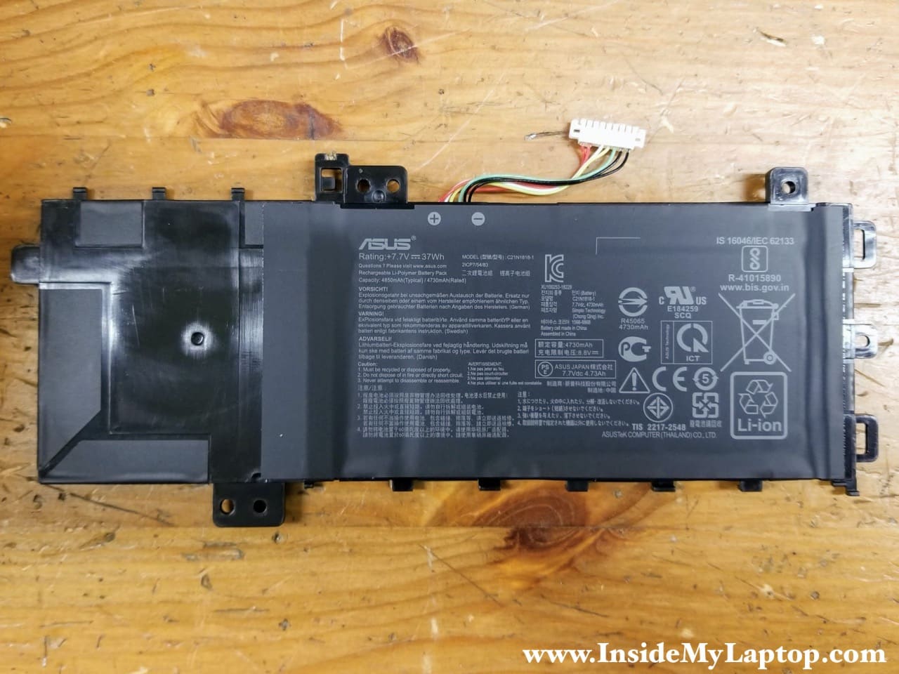
Here’s the other side of the battery.
Asus VivoBook 15 F512 X512 battery model: C21N1818-1.
Removing RAM, 2.5″ HDD and M.2 SSD
Asus VivoBook 15 F512 X512 motherboard has 4GB non-removable memory (soldered) and one RAM slot which can take up to 16GB DDR4 memory module. Maximum memory for this laptops is 20GB.
STEP 9.
Remove the memory module and replace it with a larger capacity module if necessary.
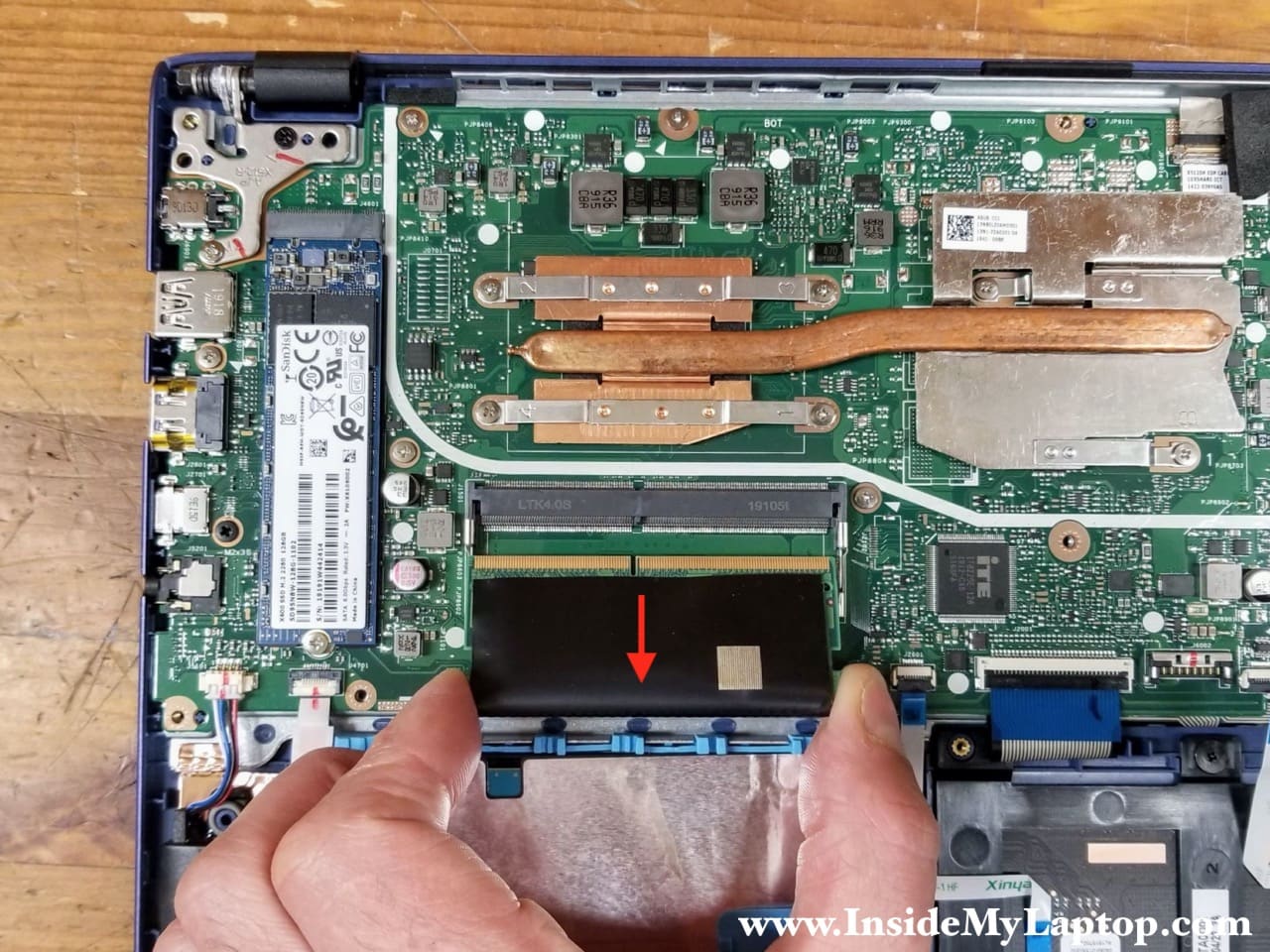
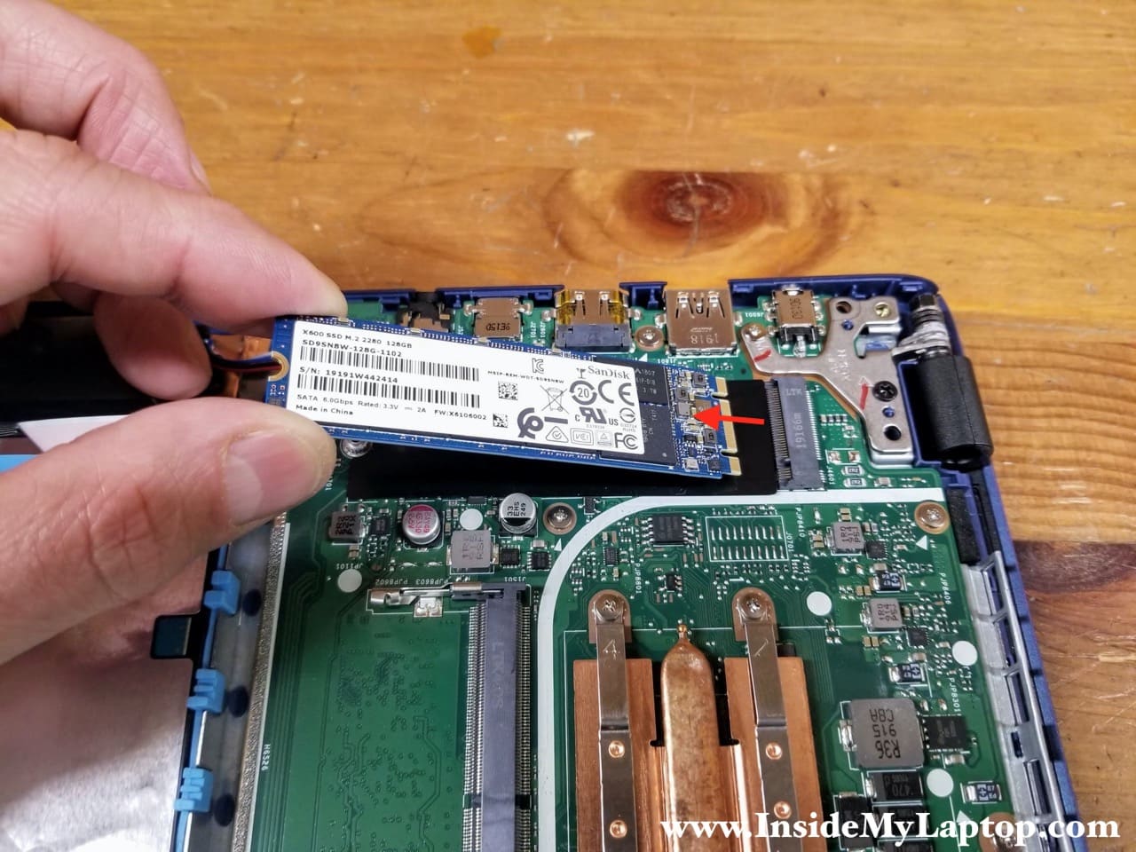
STEP 10.
Remove one screw securing the M.2 SATA SSD and pull the SSD out. This is type 2280 M.2 SSD.
STEP 11.
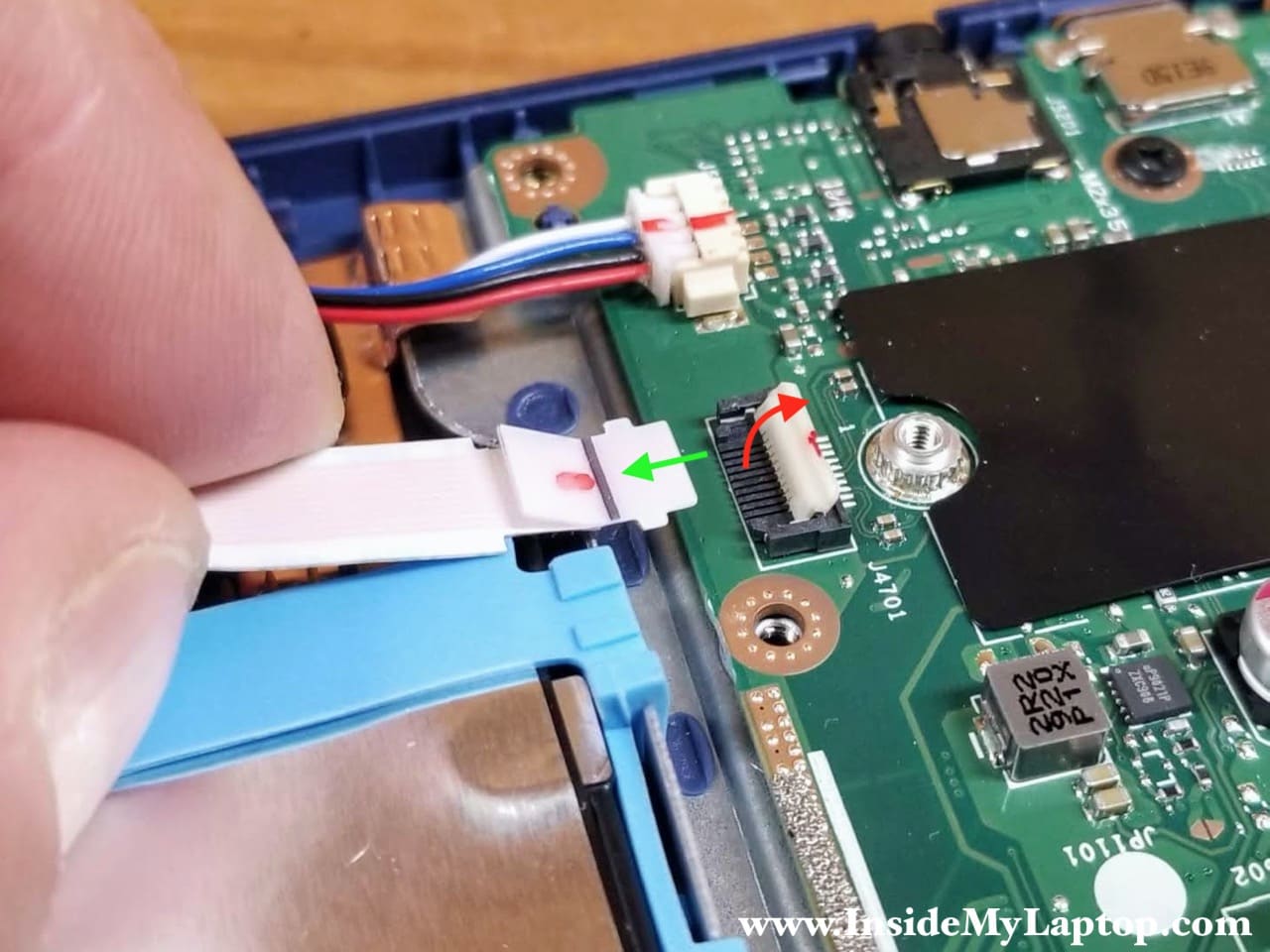
Disconnect the 2.5″ SATA hard drive cable from the motherboard.

Unlock the connector before removing the cable.
STEP 12.
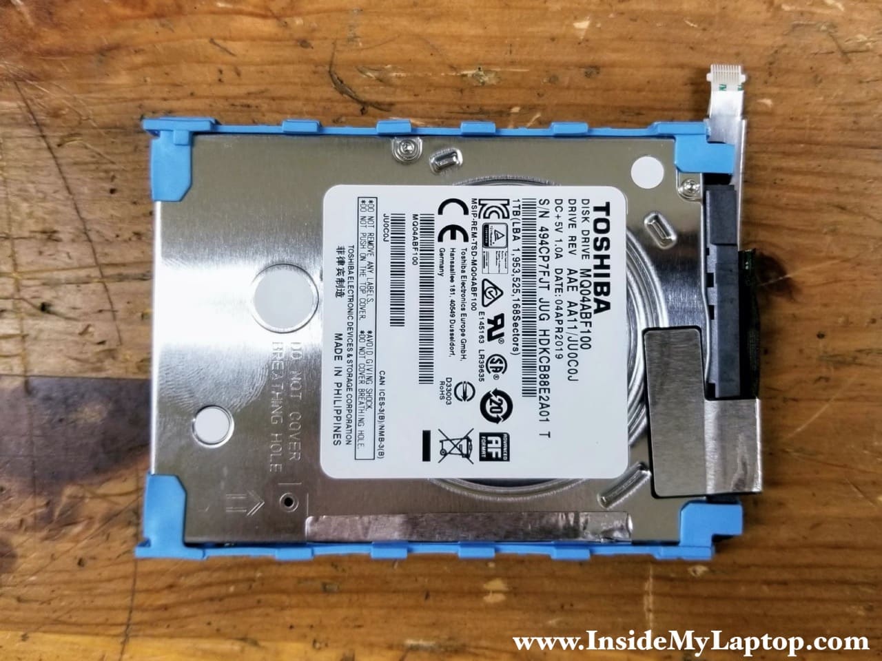
Remove the 2.5″ hard drive from the laptop.
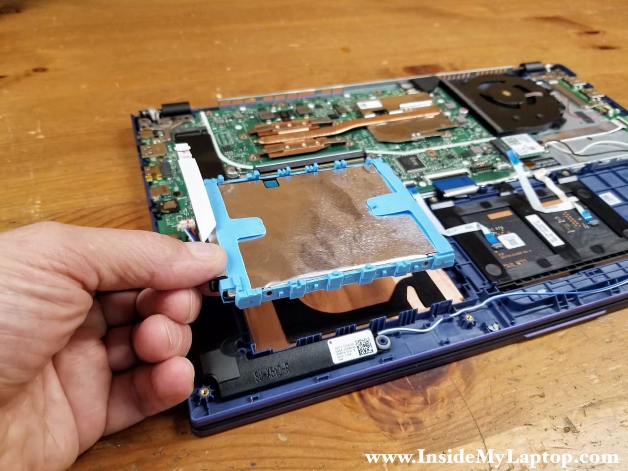
This is a regular 1TB 2.5″ spinning SATA hard drive. I would strongly recommend replacing it with a 2.5″ solid state drive which is much faster. When you upgrade the hard drive, you’ll have to transfer the SATA cable and the rubber sleeve to the new drive.
Removing the cooling fan
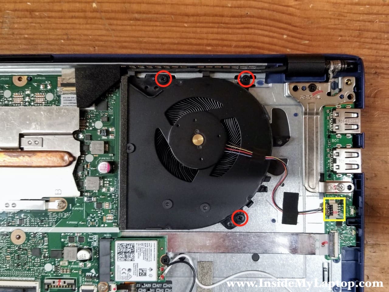
STEP 13.
Remove three screws securing the cooling fan. Disconnect the fan cable from the USB board.
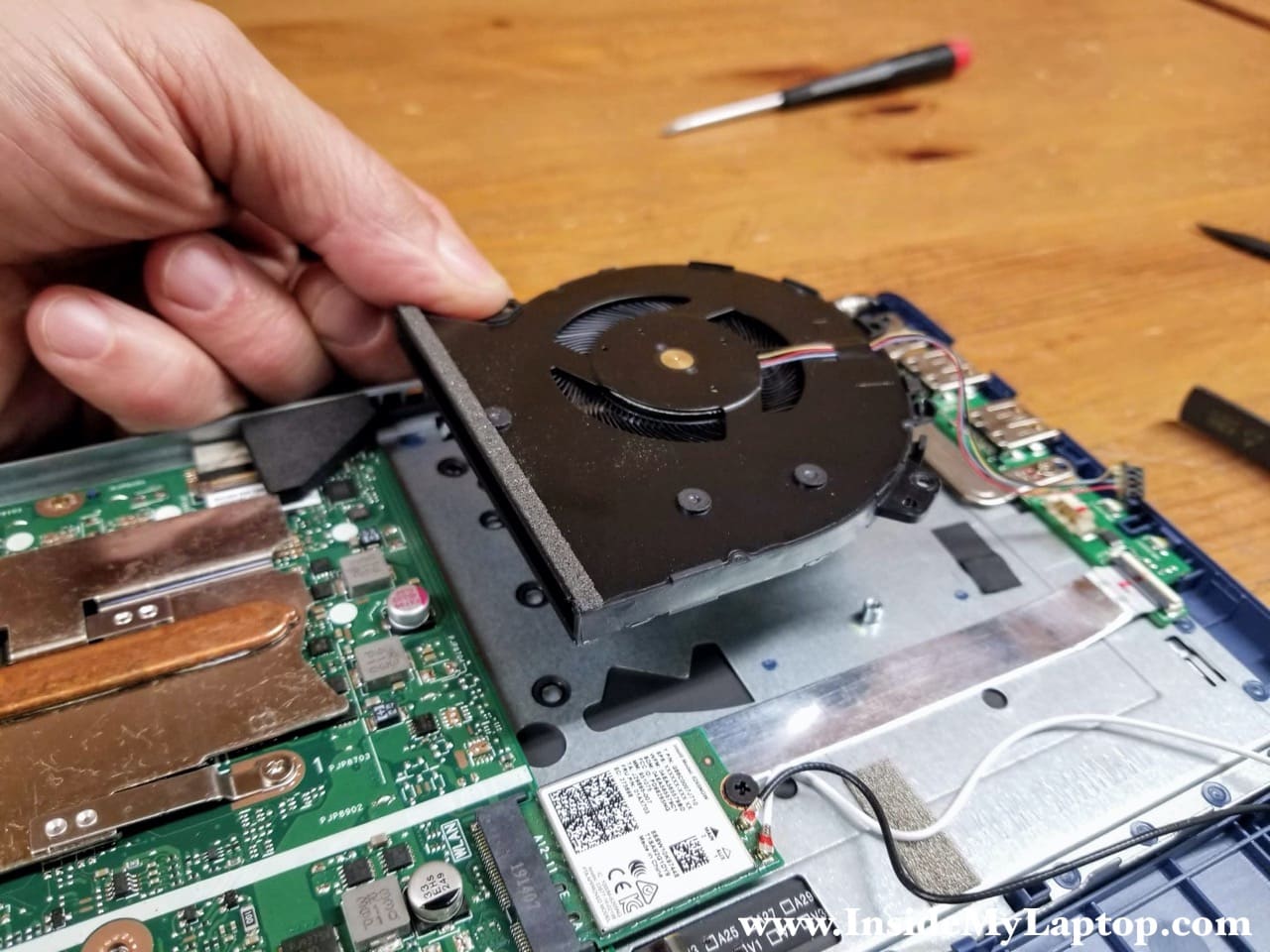
STEP 14.
Lift up and remove the cooling fan.
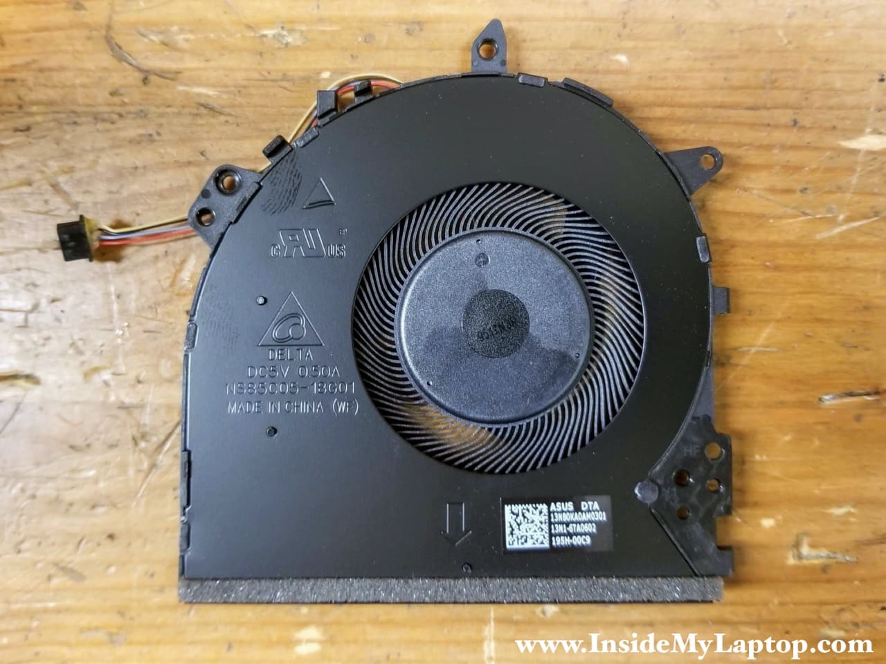
Here’s the other side of the fan (part number 13NB0KA0AM0301).
Removing the display panel
STEP 15.
Disconnect the display video cable which is hidden under the padding foam.
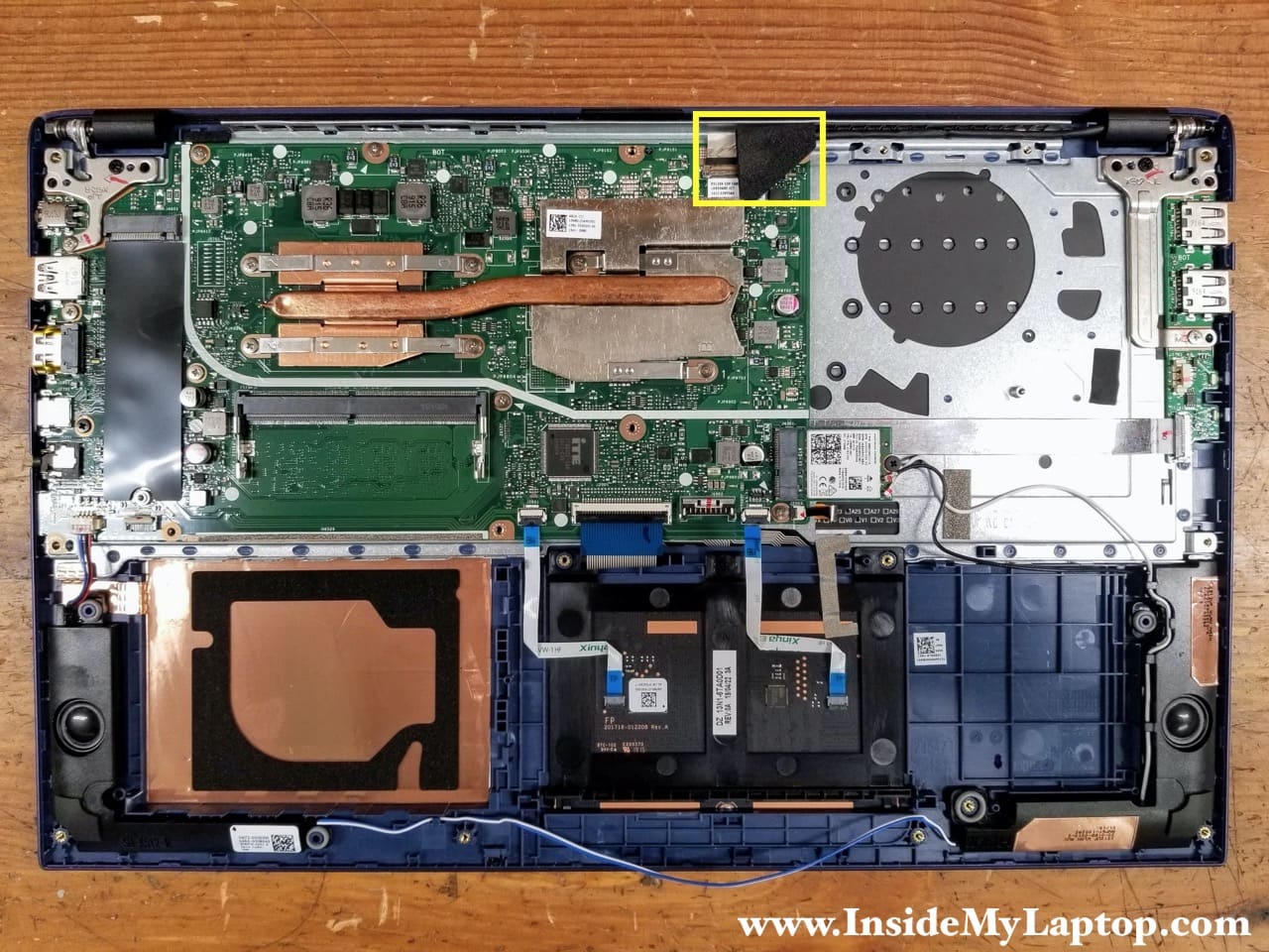
Lift up and remove the padding foam which has an adhesive tape on the bottom.
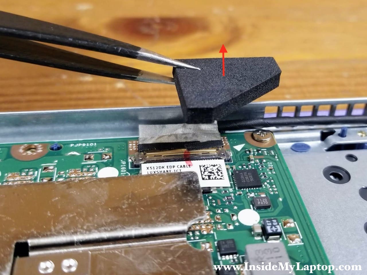
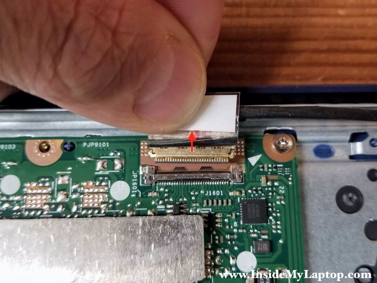
Peel off the clear tape and unplug the display video cable from the motherboard.
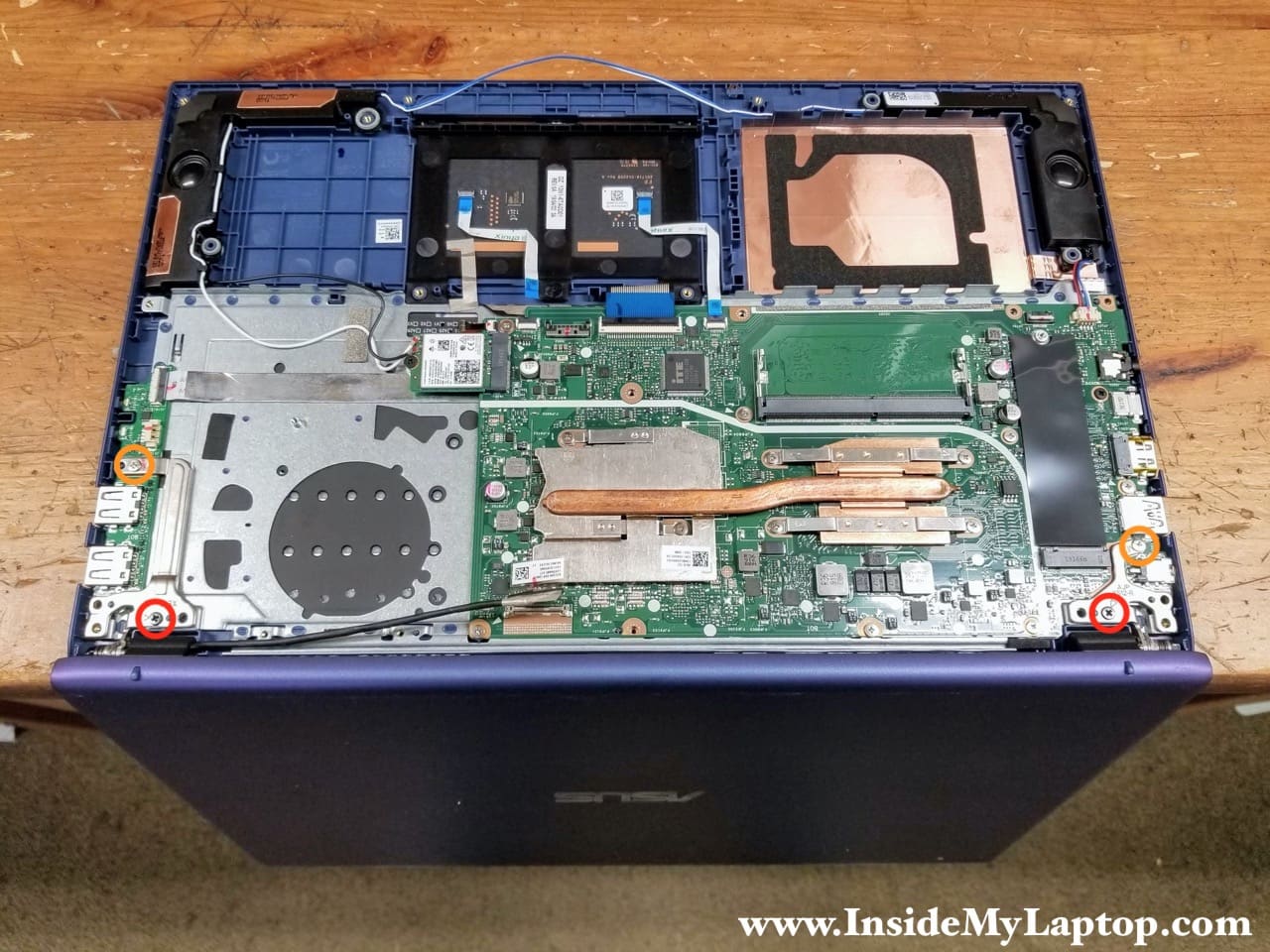
STEP 16.
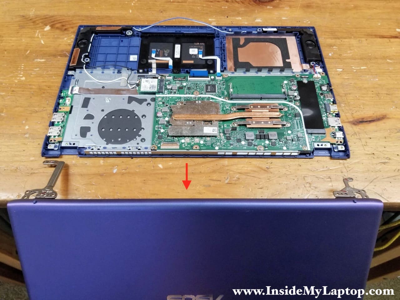
Open the display panel 90 degrees and place the laptop upside down on the edge of your desk.
Remove four screws securing the display hinges.
STEP 17.
Now you can separate the display panel from the top case assembly and remove it.
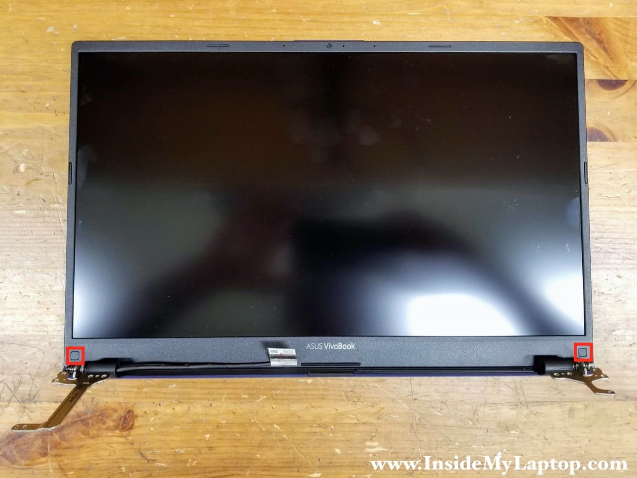
I don’t show how to remove the LCD screen in this guide but it shouldn’t be difficult. I believe the screen removal procedure is pretty much standard:
1. Remove two screws from the lower left and right corners of the display assembly.
2. Remove the screen bezel.
3. Remove all screws securing the screen.
4. Disconnect the display cable from the back of the screen.
Removing the USB board and the motherboard
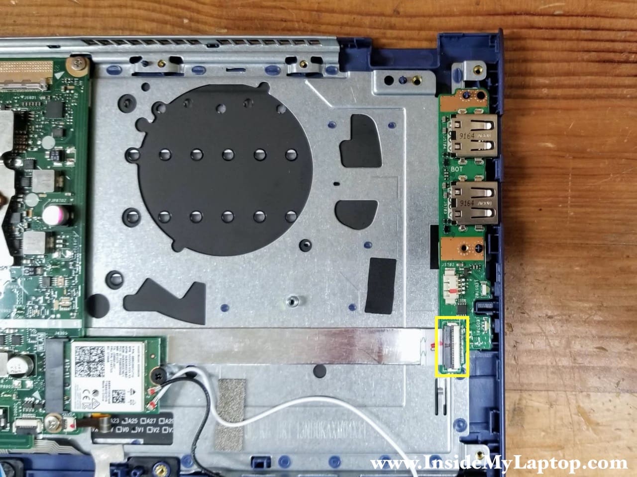
STEP 18.
Disconnect the I/O cable from the USB board.
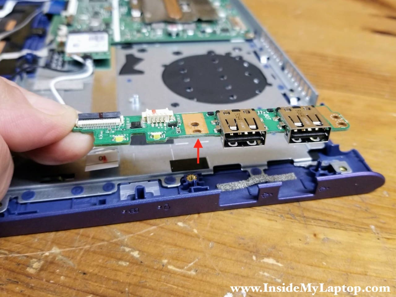
STEP 19.
Lift up and remove the USB board.
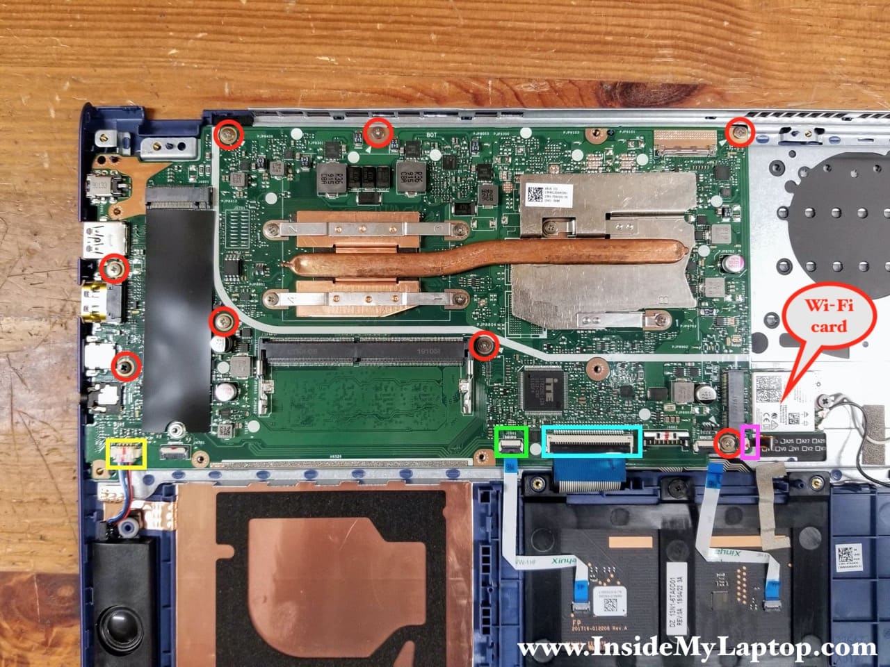
STEP 20.
Remove all screws securing the motherboard and disconnect the following color-coded cables:
– Speaker cable (yellow).
– Touchpad cable (green).
– Keyboard cable (blue).
– Keyboard backlight cable (pink).
Also, its necessary to remove the Wi-Fi card.
Now you can separate the motherboard from the top case and remove it.
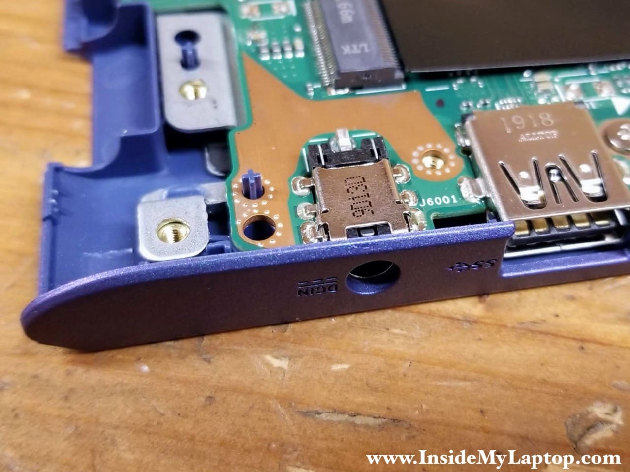
The DC-IN power jack soldered to the motherboard. If it fails, you’ll have to unsolder the failed DC jack and replace it with a new one.
Removing the touchpad
STEP 21.
Remove one screw securing the touchpad and disconnect two cables. Remove the touchpad.
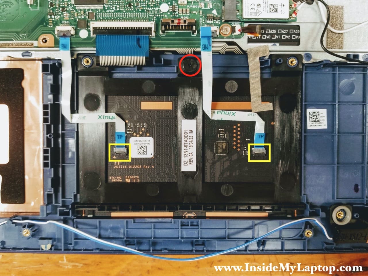
The keyboard is not removable because it’s permanently attached (riveted) to the top case. If the keyboard fails, you’ll have to replace the entire top case assembly.
Michael
Hello, I have taken this partially apart and did not find the cmos battery. Could u tell me where it is located or point me in the right direction for jump pins to short it out? I am desperately needing to reset the bios admin password. I bought this and it has been refurbished, Magic Simba did not reset the password before it was sent to me. Thanks so much.
IML Tech
It looks like the motherboard doesn’t have the CMOS battery. Sorry, I don’t know how to clear the password.
Mark James
Hello Michael, These models have a Burn In UEFI password, even if there was a battery in these newer models, it wouldn’t reset it, Best course of action you can do is speak to Asus and provide them some form of proof of purchase, they will check to see if the model is reported lost or stolen to them (if previously registered) if it hasn’t then you should be able to get a quote from them to factory flash the unit for you.
The only other way would be to find and de-solder the system bios, this model does not contain a separate SMC (system management controller), so for a lot of models in this configuration a replacement CMOS chip would fix the issue, However im not sure on the availability of the CMOS chips in a programmed state for that particular model. that would require some investigation.
Hope that helps you. (all be it 2 years later)
Don
Hello,
Great instructional for opening up the laptop. I have a 512J model and it does not have a lit keyboard. Do you know if I could swap the keyboard for a lighted one?
Thx, Don