
In this guide I show how to disassemble Asus Q553 Q553U Q553UB Notebook PC.
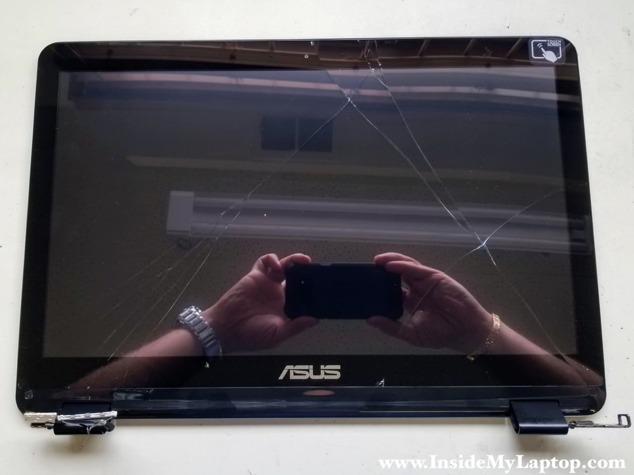
In the first part of the guide I will tear apart the laptop case and in the second part I will take apart the display assembly. As you noticed, in my laptop the screen digitizer glass is cracked and it stopped working. We’ll take a look if it’s easy to replace the digitizer or not.
Taking apart the laptop case.
STEP 1.
Remove all screws from the bottom case.

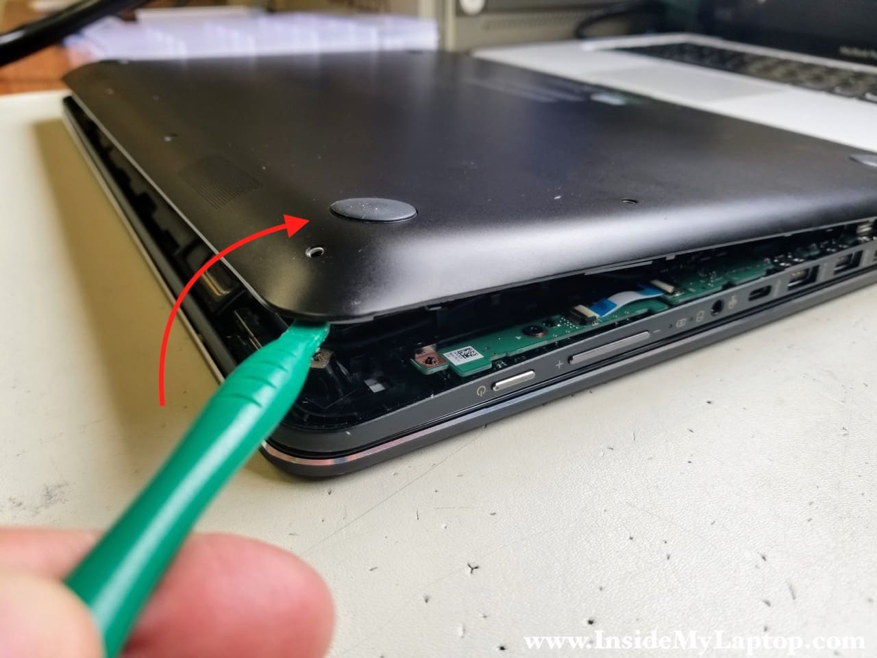
STEP 2.
Separate the bottom case from the top case and remove it.
STEP 3.
Remove four screws attaching the battery to the top case.
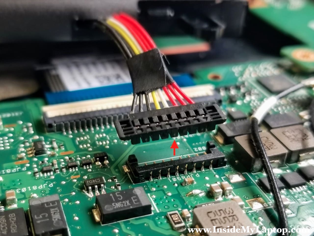
The speaker cable attached to the right side of the battery. While removing the battery you will have to un-route the cable from the guided path.
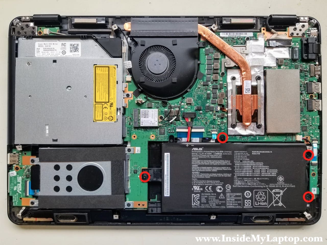
Lift up the battery connector and unplug it from the motherboard.
Replacement battery type N593UB-1A.
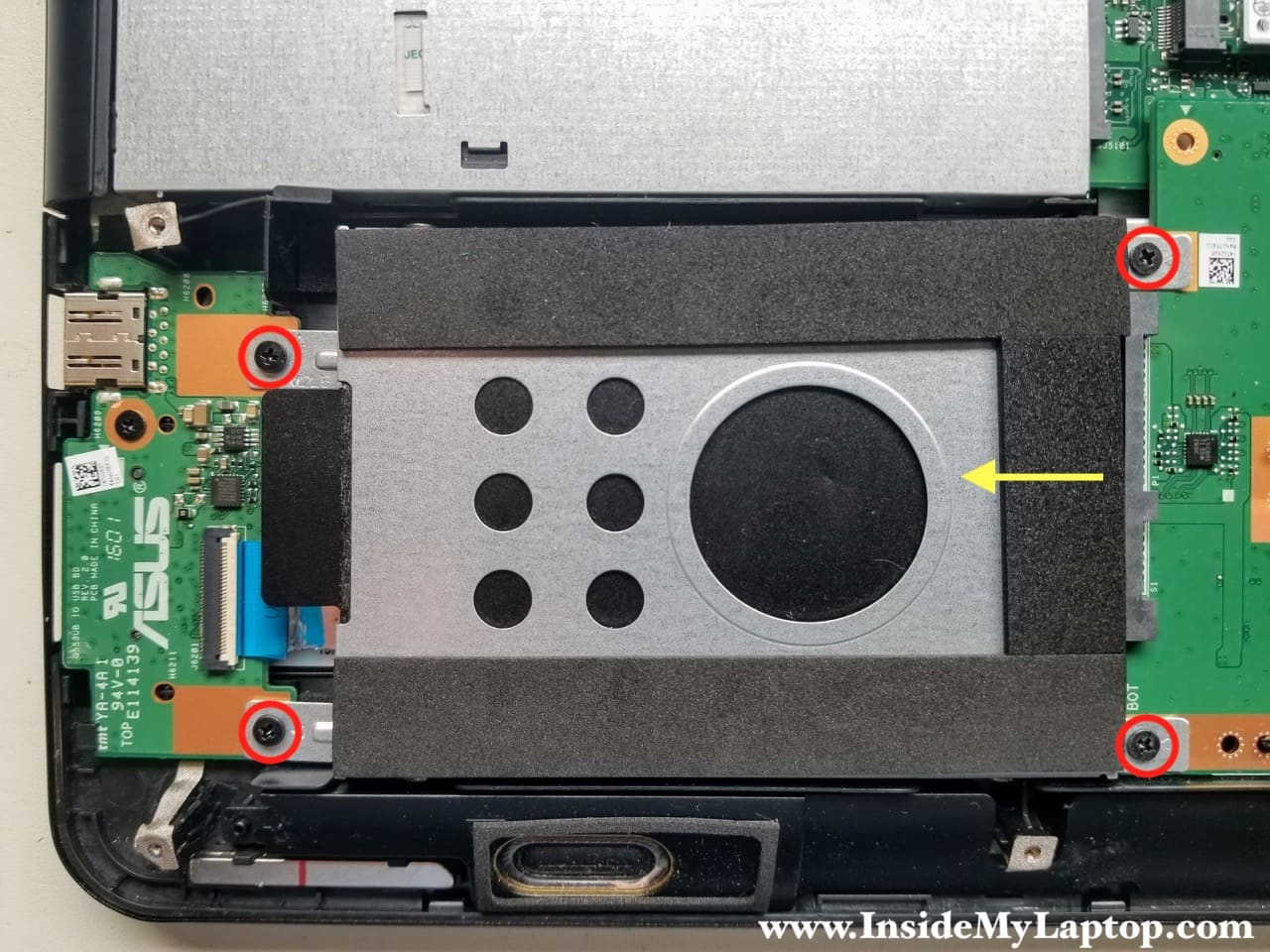
STEP 4.
Remove four screws securing the hard drive bracket. Slide the hard drive assembly to the left to disconnect it from the motherboard. Remove the hard drive.
I recommend upgrading this regular hard drive to a 2.5″ SATA solid state drive to improve laptop performance.
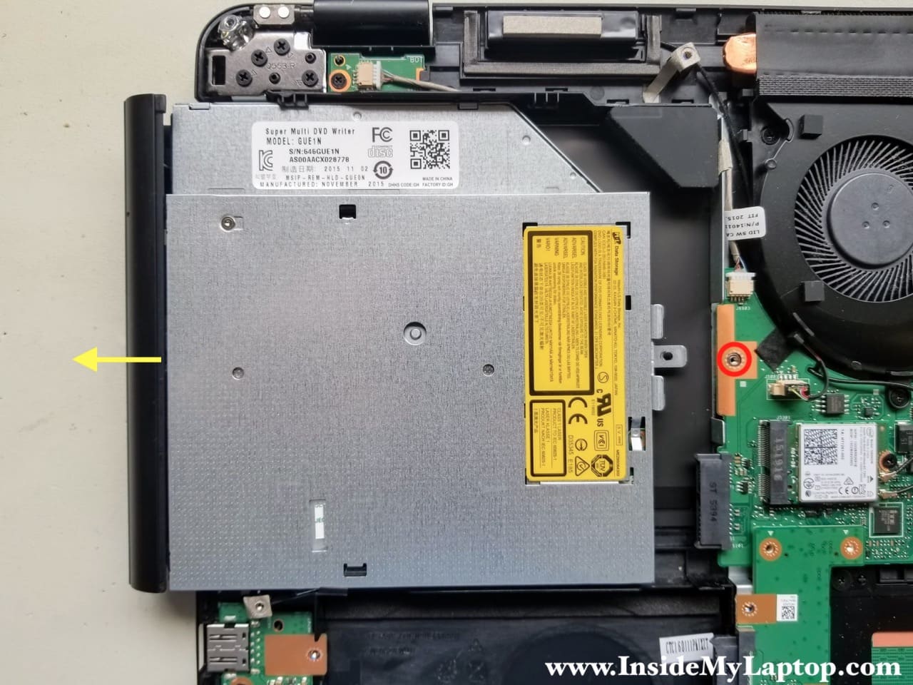
STEP 5.
Remove one screw securing the optical CD DVD drive. Slide the optical drive to the left and remove it from the laptop case.
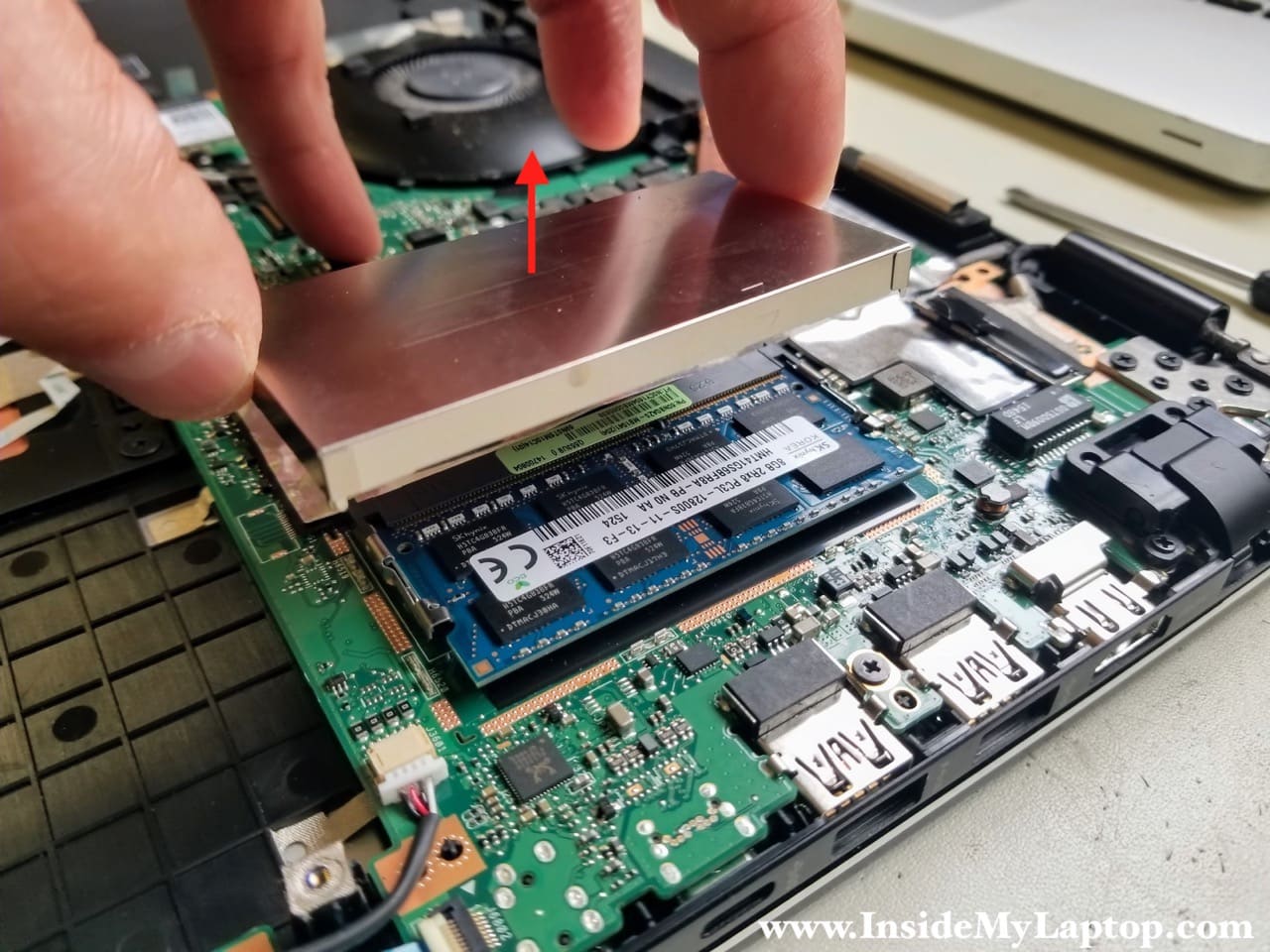
STEP 6.
Asus Q553 Q553U Q553UB motherboard has only one removable memory module. The memory module located under the metal cover which can be easily removed.
You can leave the memory module connected to the board unless you are replacing it with another one.
You can install up to 8GB DDR3-12800 SODIMM module into this slot.
The second memory module integrated into the logic board and I will show where it’s located later, after I remove the motherboard from the case.
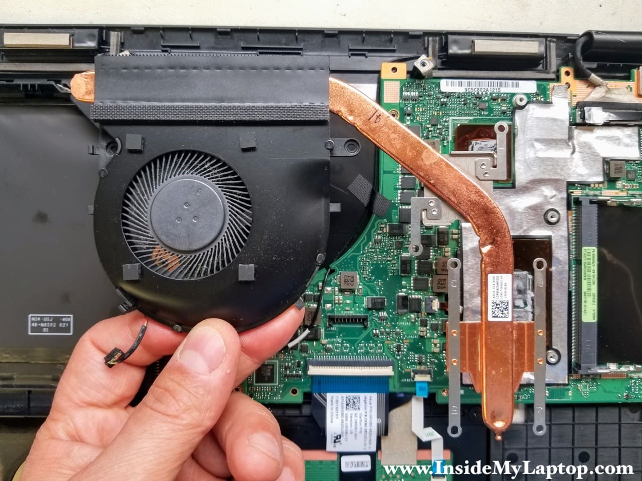
STEP 7.
Remove there screws from the cooling fan and four screws from the heatsink.
Disconnect the fan cable from the motherboard.

STEP 8.
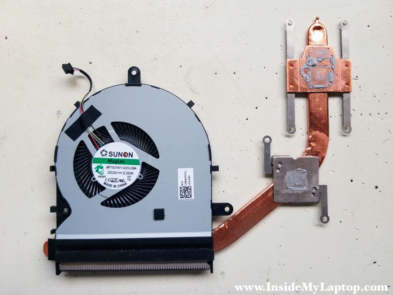
Lift up and remove the cooling module assembly.
The cooling fan is permanently attached to the heatsink.
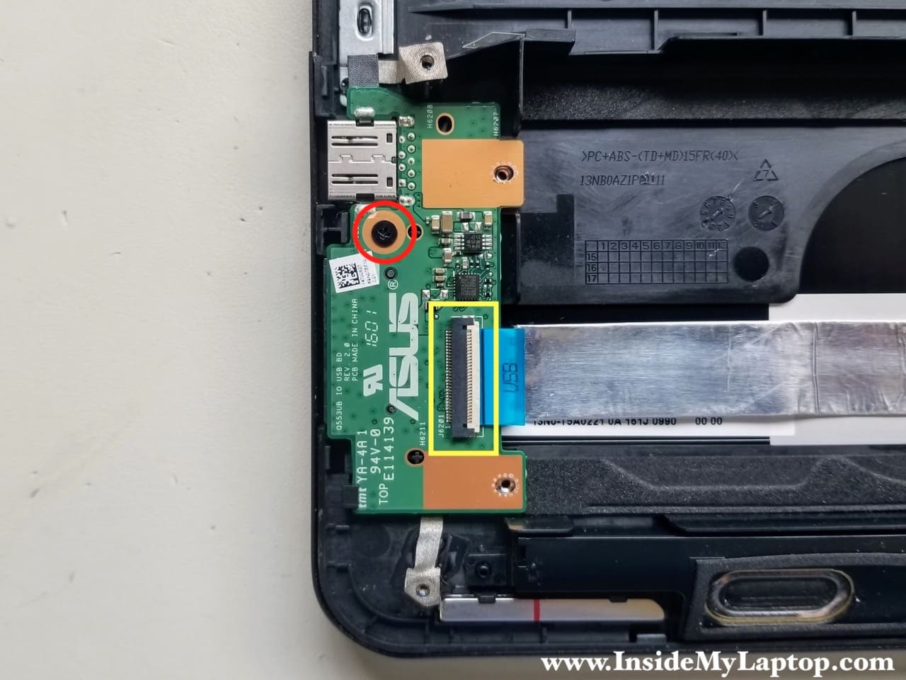
STEP 9.
Remove one screw from the USB SD card reader board.
Disconnect the I/O cable from the board.
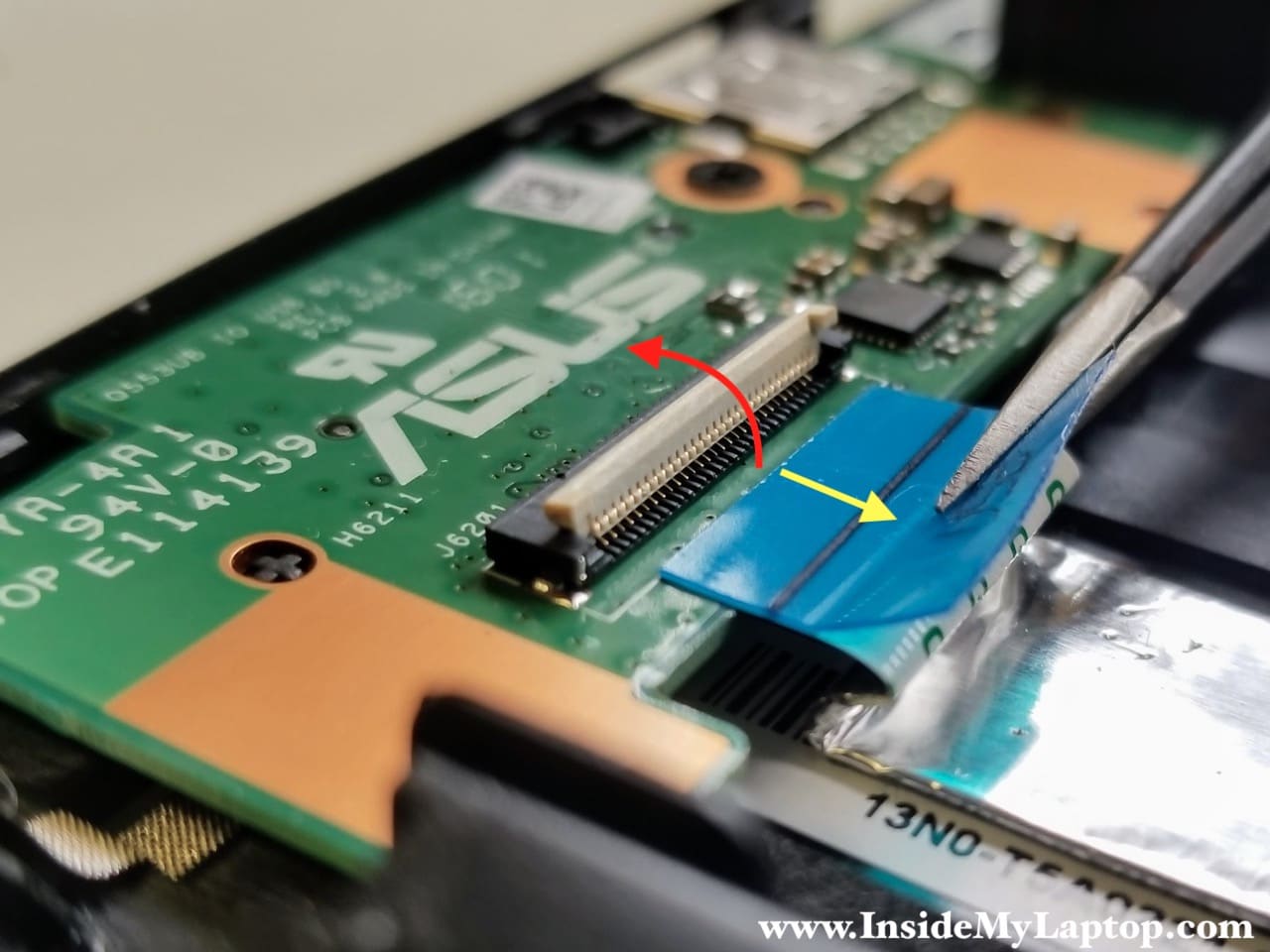
Here’s how to disconnect the cable.
- Unlock the connector by lifting up the locking tab (red arrow).
- Pull the cable out of the connector (yellow arrow).
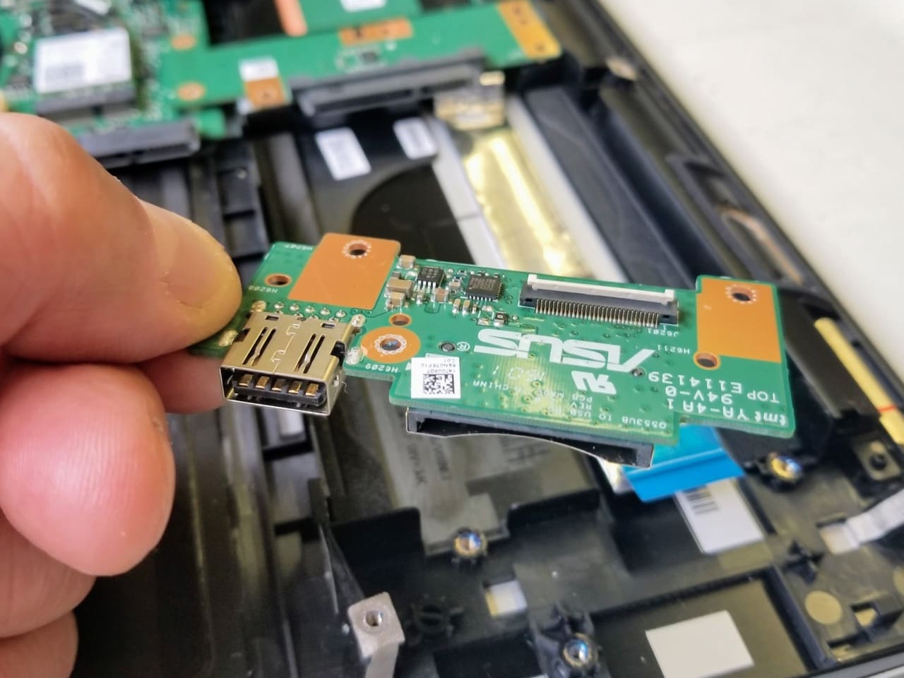
STEP 10.
Remove the USB SD card reader board.
STEP 11.
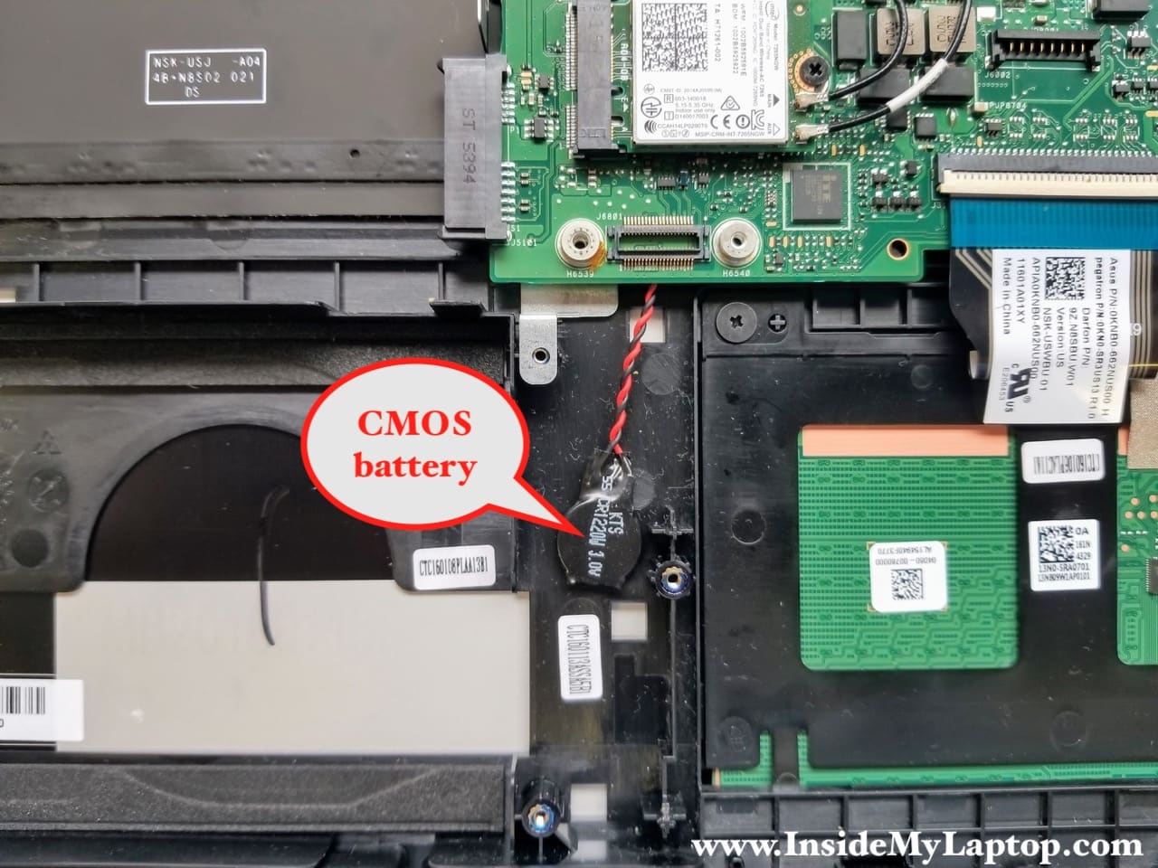
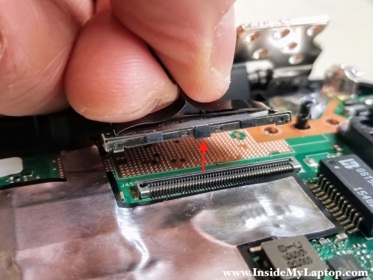
Remove the hard drive board with the cable.
You will have to lift up the board in order to unplug it from the connector on the motherboard.
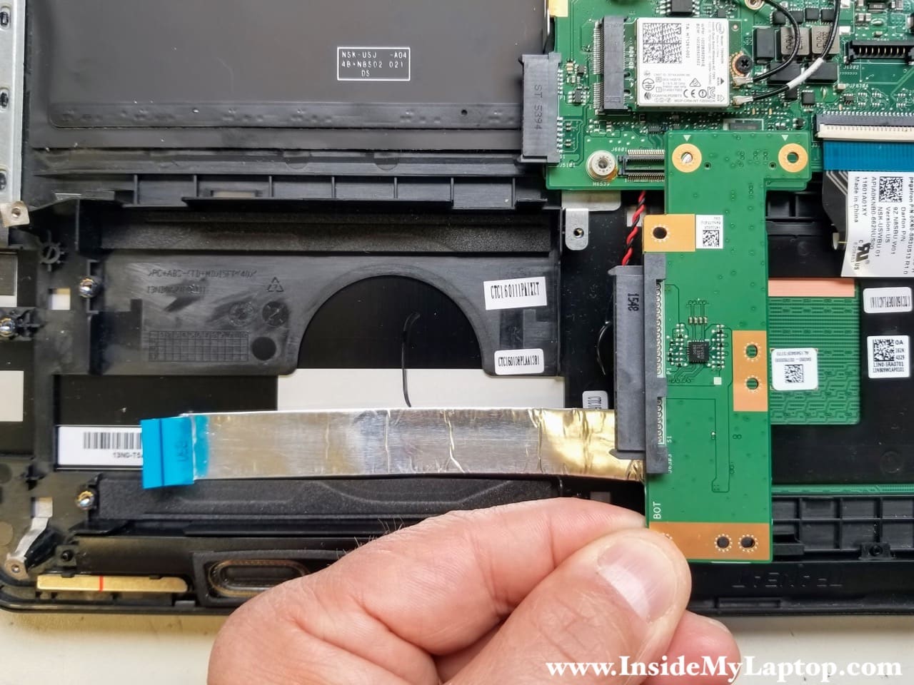
The CMOS battery is hidden right under the hard drive board.
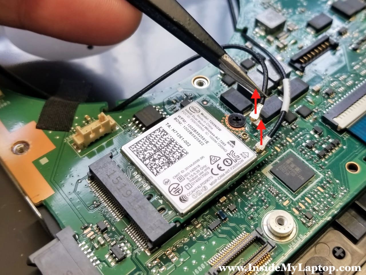
STEP 12.
Disconnect both antenna cables from the WLAN card. It’s a dual band wireless-AC card.
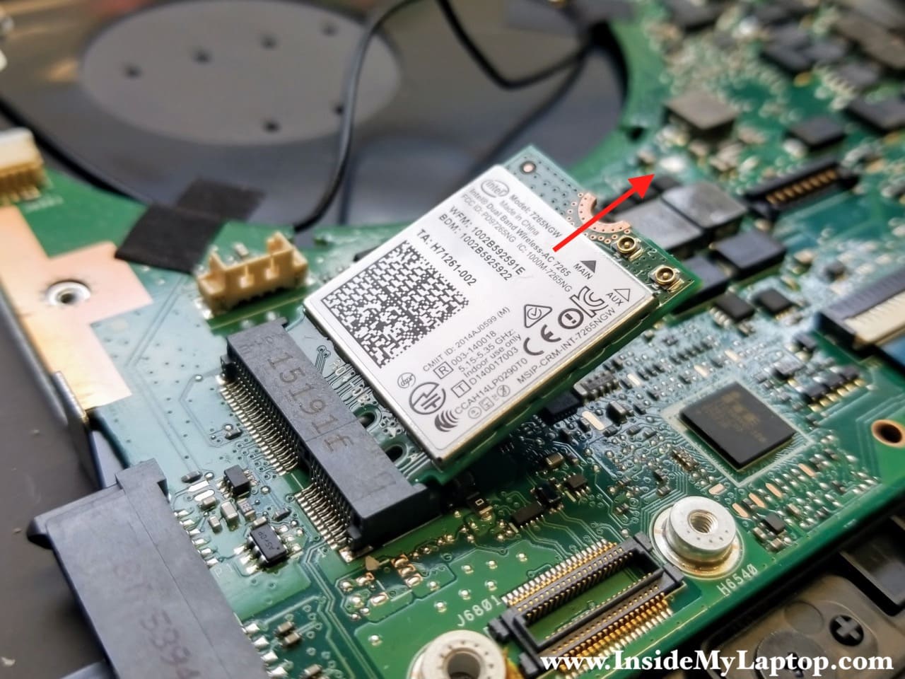
STEP 13.
When you remove one screw securing the WLAN card, it will pop up at a 30 degree angle.
Pull the WLAN card out of the slot.
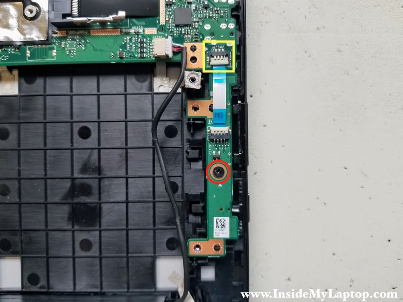
STEP 14.
Remove one screw from the power button and volume control board.
Disconnect the cable.
STEP 15.
Remove the power button and volume control board.

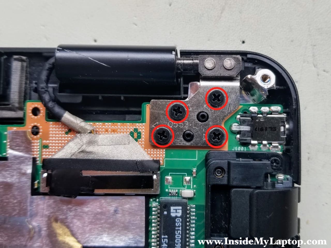
STEP 16.
In order to remove the motherboard, it’s necessary to open up the left hinge.
Remove four screws from the left hinge.
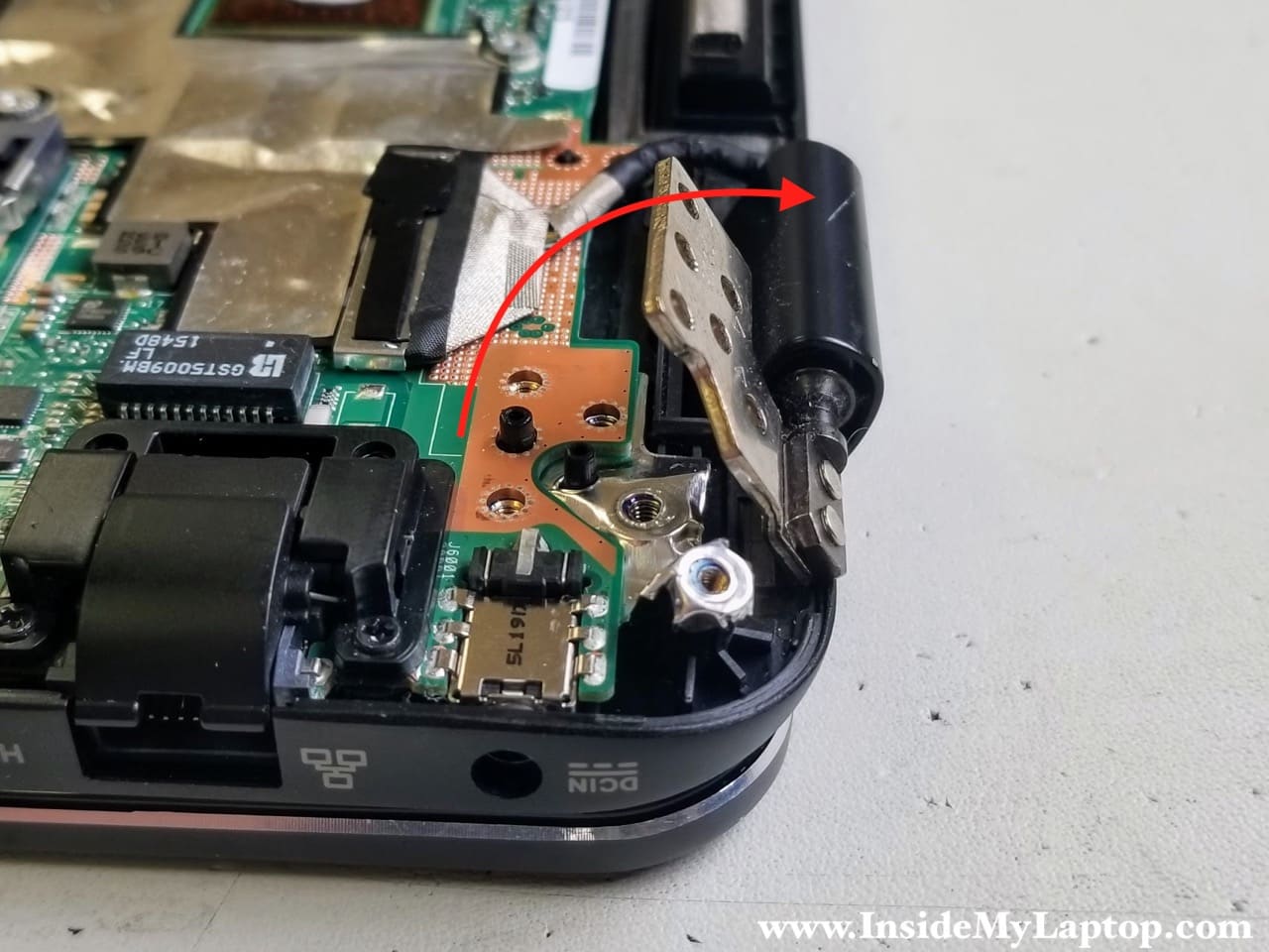
STEP 17.
Lift up the left side of the hinge so it opens up at a 60 degree angle.
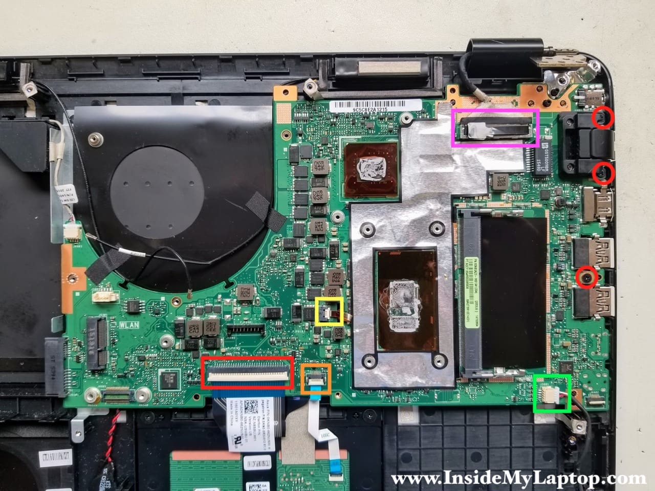
STEP 18.
Remove three motherboard screws. Two of them located on the LAN port cover.
Disconnect the following cables:
- Keyboard data cable (red rectangular).
- Touchpad cable (orange square).
- Speaker cable (green square).
- Keyboard backlight cable (yellow square). Attention!!! It’s easy to overlook this cable because the connector is small and located in the middle of the motherboard.
- Display video cable (purple rectangular).
Both wireless antenna cables are taped to the motherboard in the fan area. It’s necessary to remove the tape and separate antennas from the motherboard.
The keyboard connector unlocked the same way as other flat cable connectors.
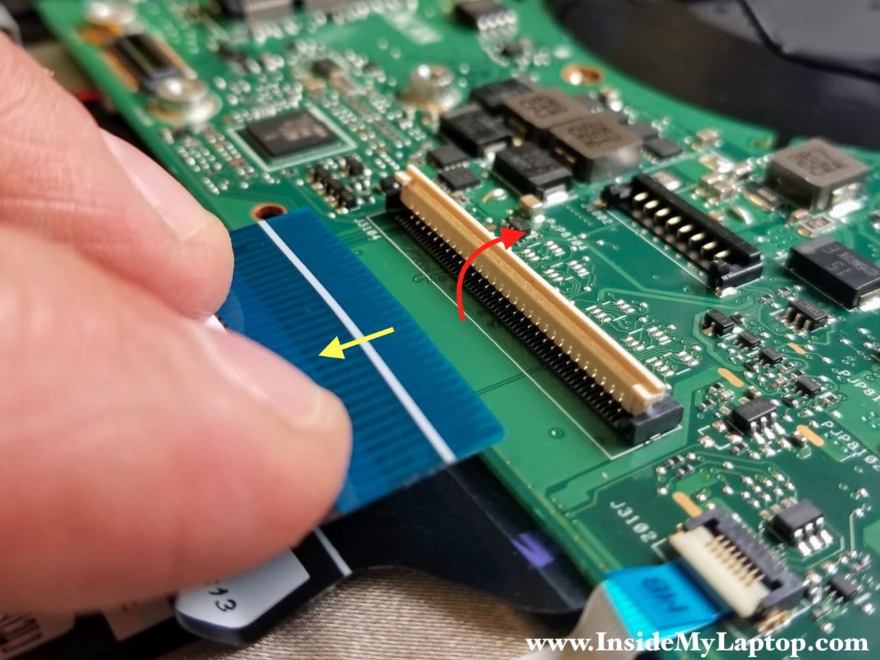
In order to disconnect the display cable simply lift up the connector using the black belt on the top.
STEP 19.
Separate the motherboard from the top case and remove it.

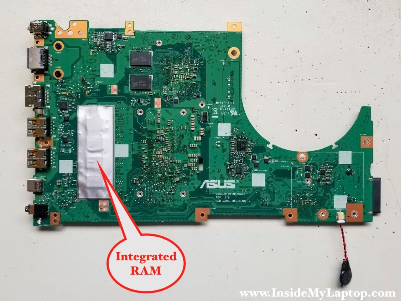
Here’s the other side of the Asus Q553 Q553U Q553UB motherbaord.
The integrated RAM located under the silver shield. It’s permanently attached to the board and cannot be removed or replaced. The DC jack also soldered but it’s possible to replace the jack.
STEP 20.
The touchpad attached to the top case by three screws. I’m not removing the touchpad in this guide but it shouldn’t be difficult.
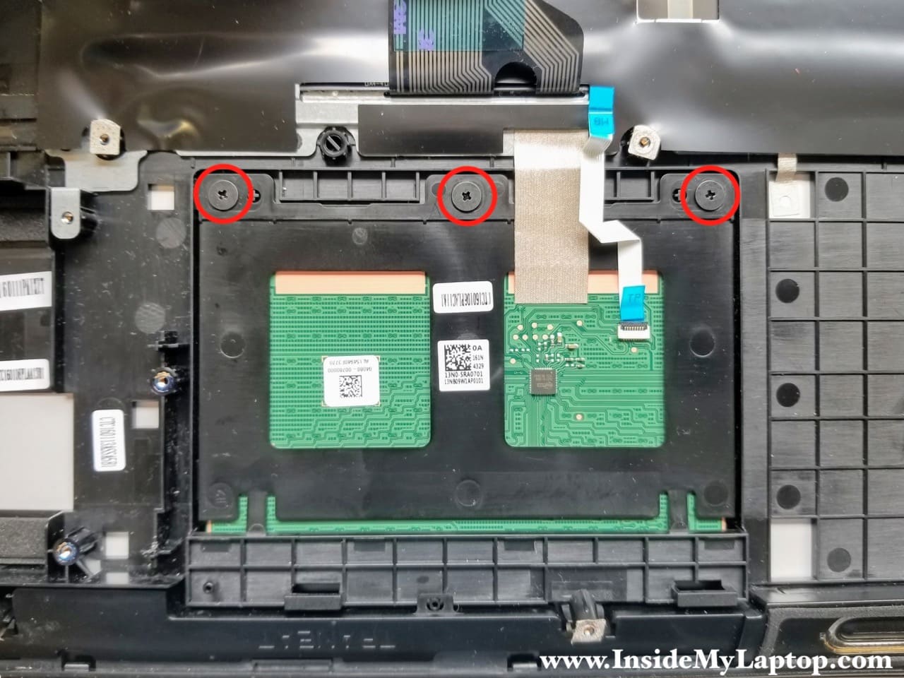
The keyboard is permanently riveted to the top case and cannot be easily removed. If your keyboard failed, I would suggest replacing the entire top case or you can try this keyboard removal method.
Removing the display and taking it apart
STEP 21.
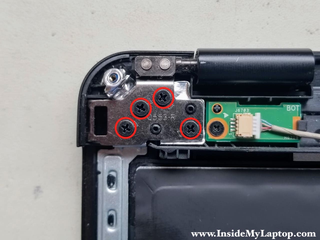
Remove four screws from the right hinge.
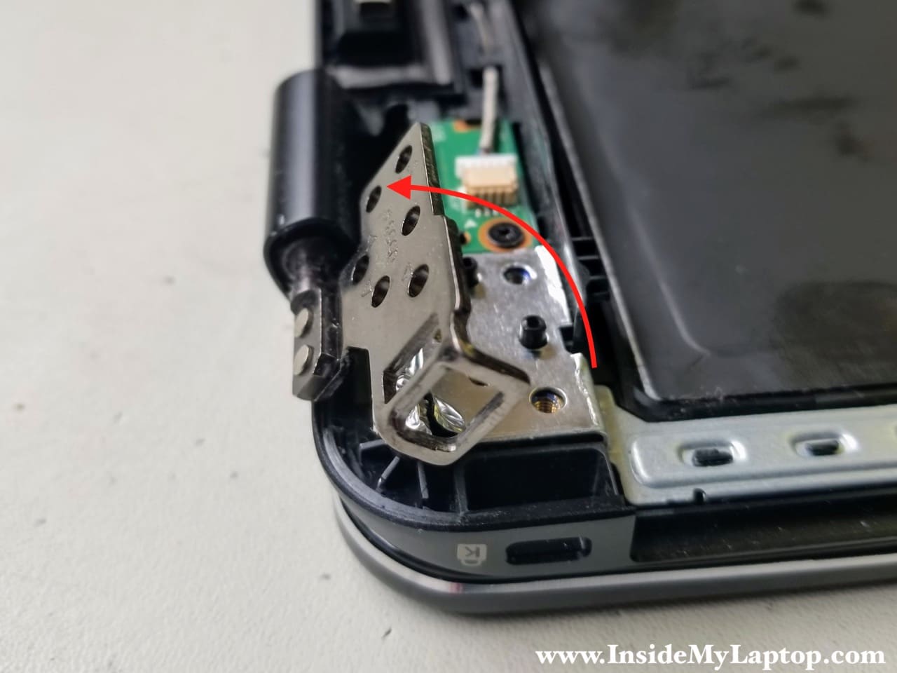
STEP 22.
Open up the right hinge the same way as the left hinge earlier in the step 17.
STEP 23.
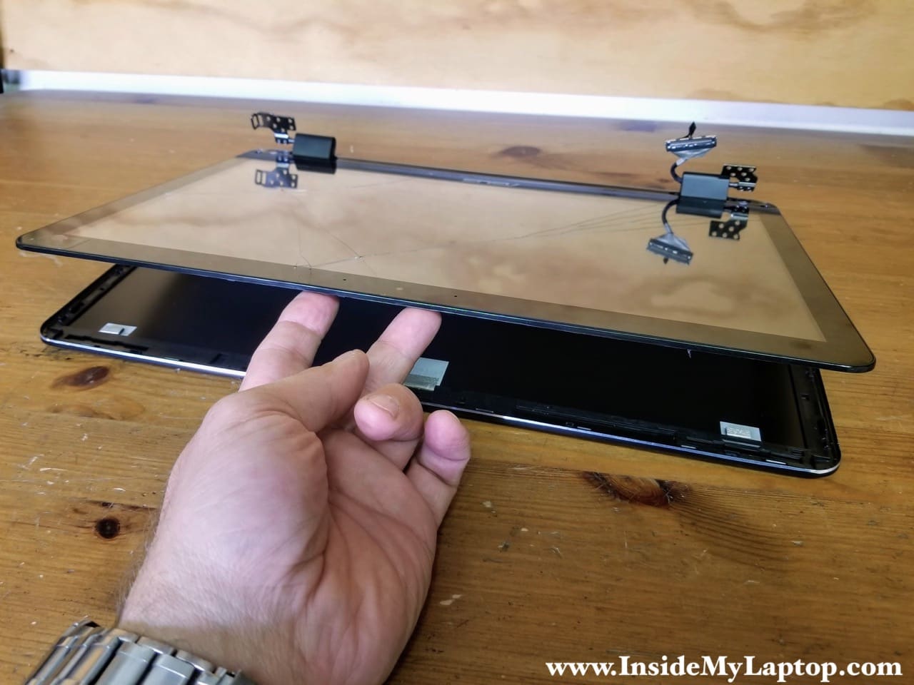
With both hinges opened up, you can easily separate the display panel from the top case.
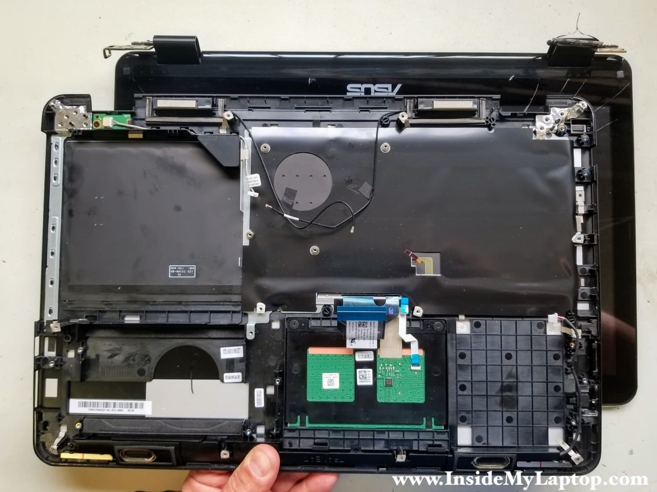
Now let’s take apart the display panel.
STEP 24.
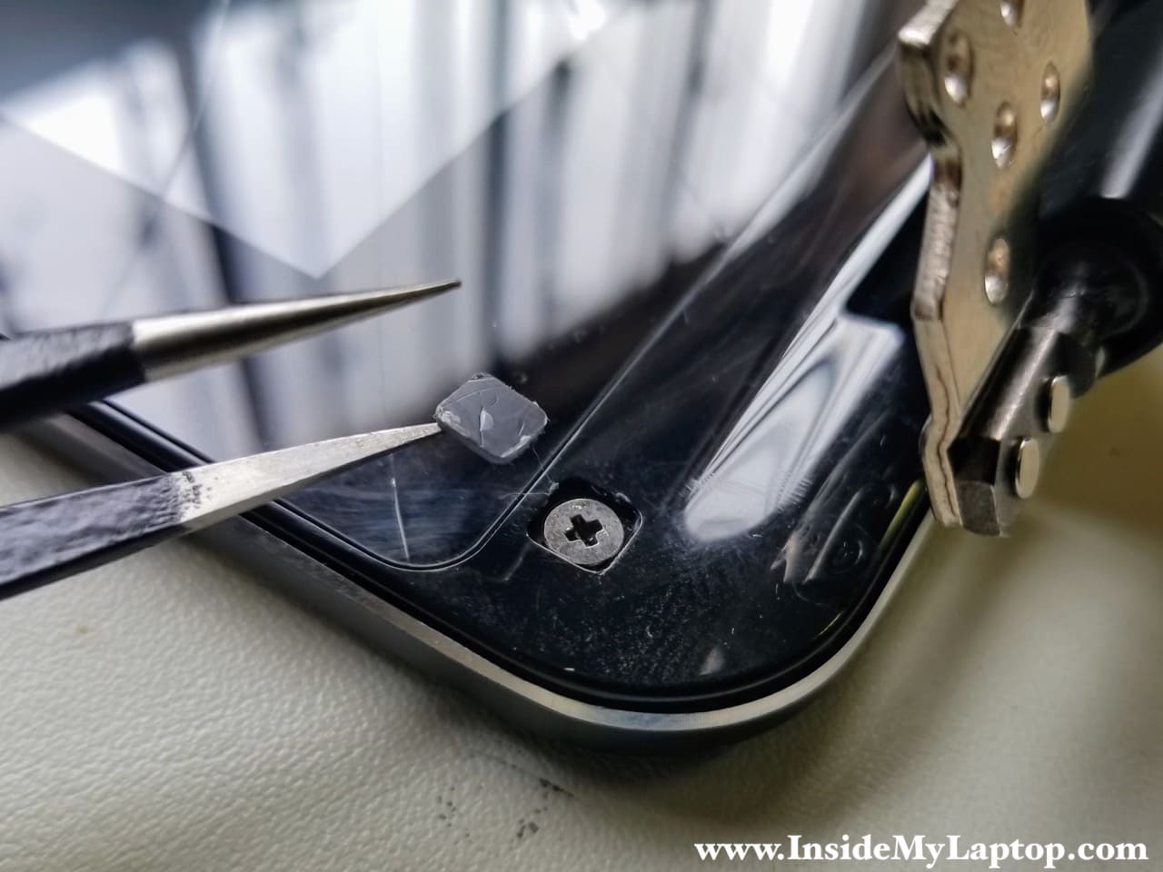
There are two screws located in the lower left and right corner of the display assembly. They are hidden under the plastic covers.
Remove both covers and both scews.
STEP 25.
Insert a think plastic case opener between the LCD screen/digitizer assembly and display back cover.
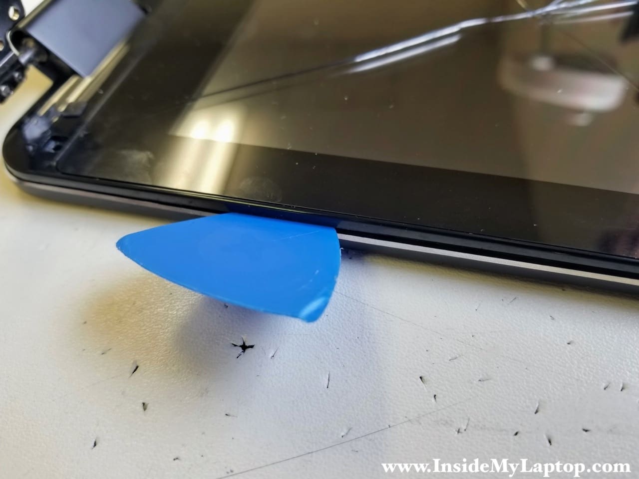
STEP 26.
Pry up and unsnap the LCD screen/digitizer assembly from the cover.
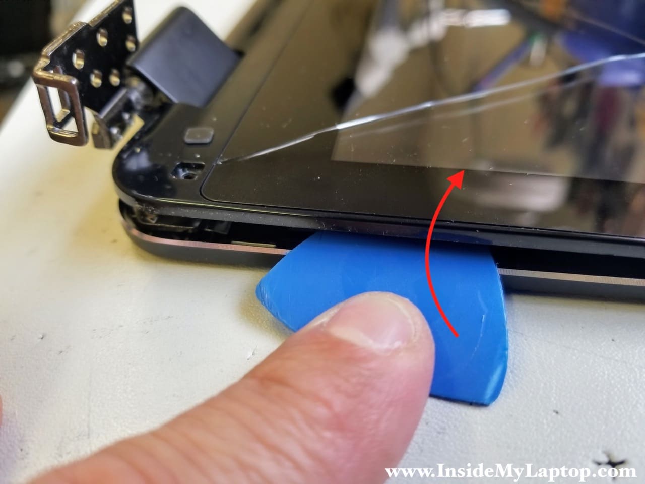
STEP 27.
Move along the side of the display separating one part from the other.
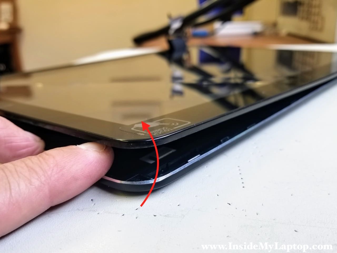
Continue separating them on the top, sides and bottom of the display assembly.
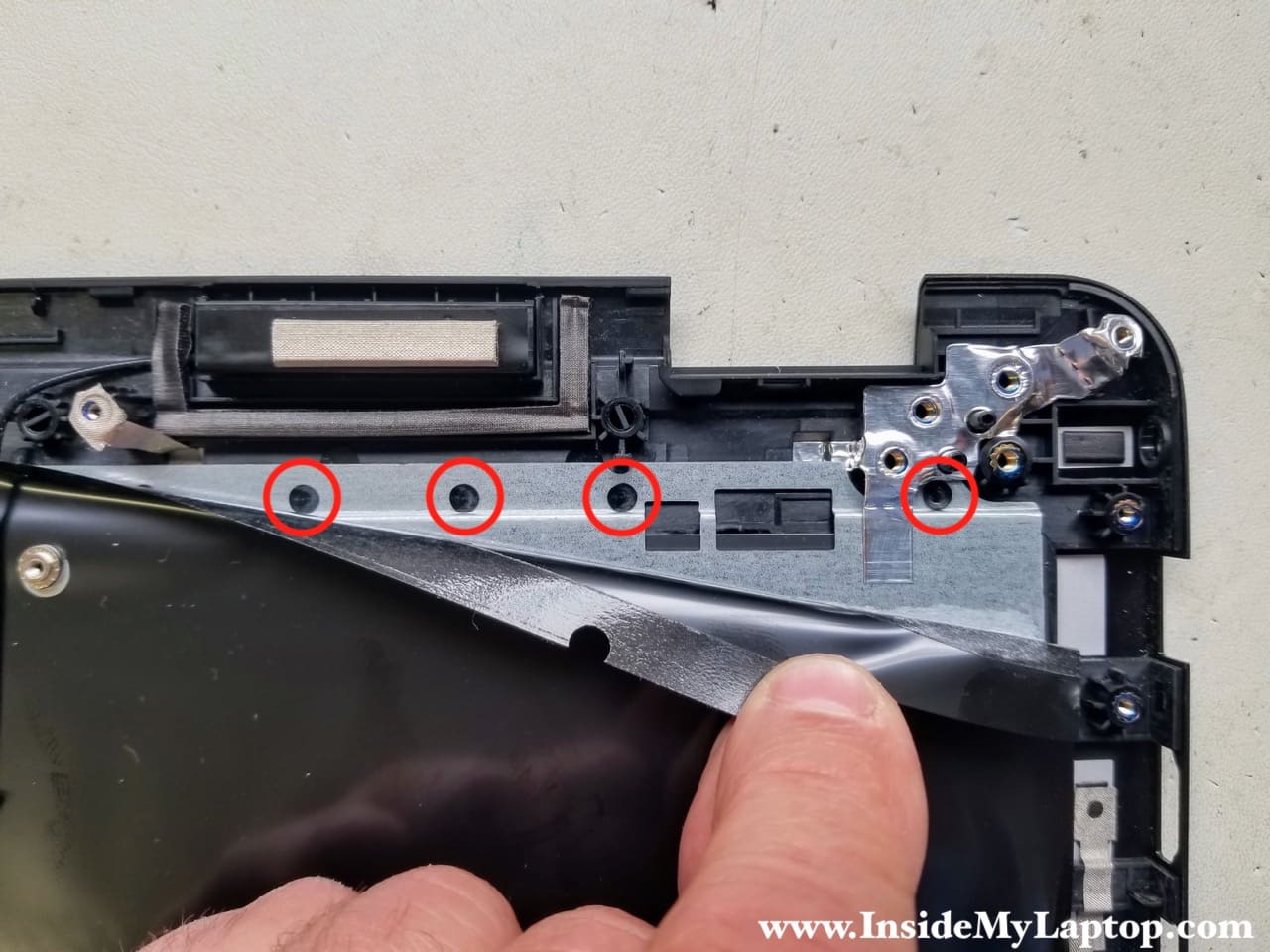
STEP 28.
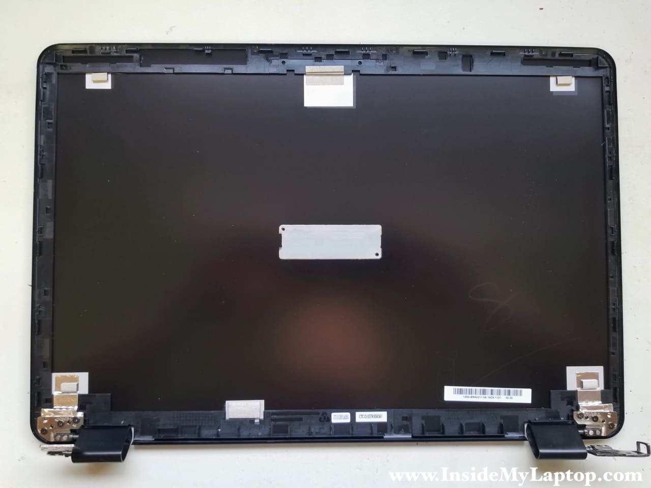
Remove the LCD screen/digitizer assembly from the back cover.
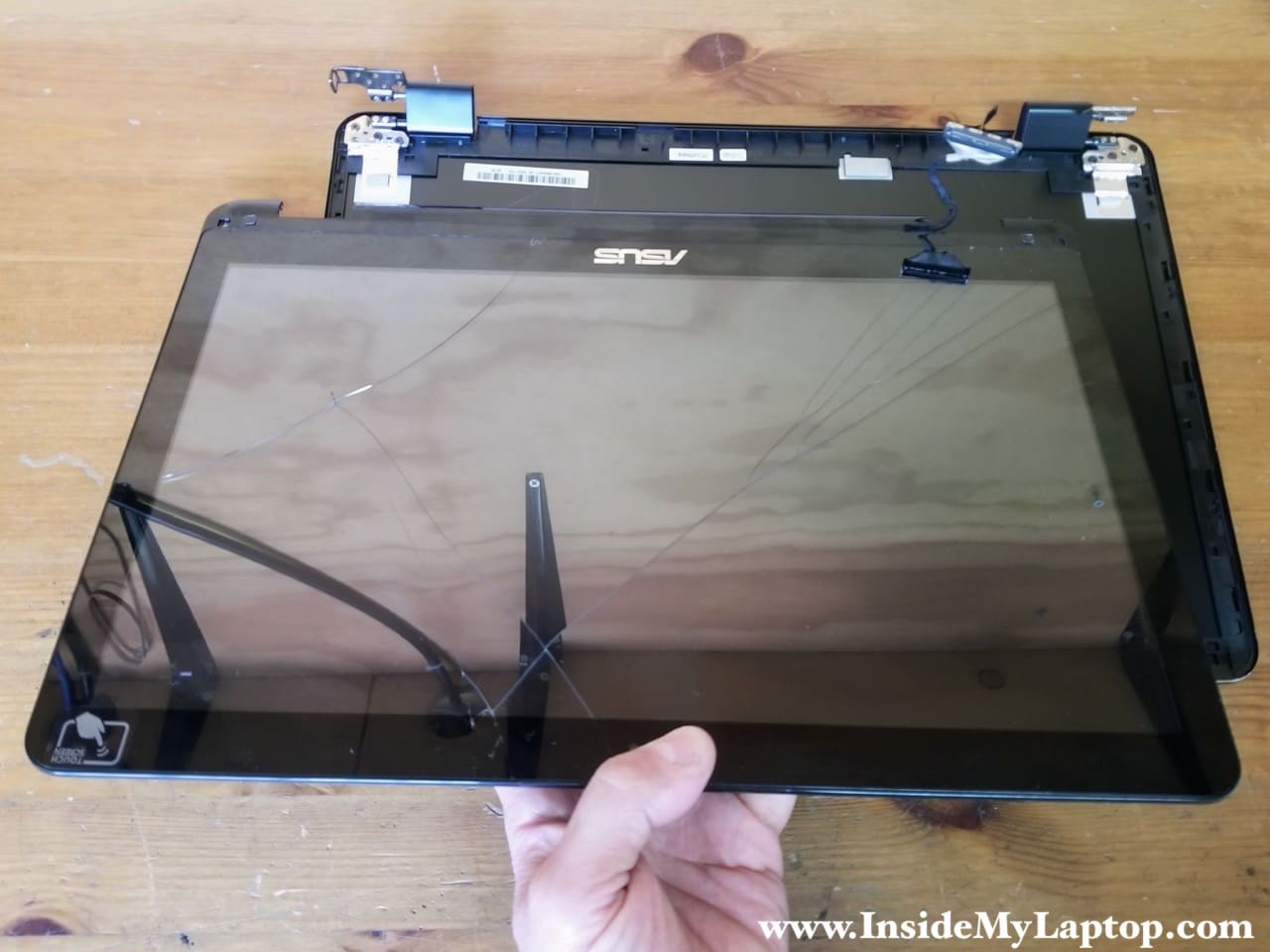
Here’s the display back cover where you can access and remove both hinges if necessary.
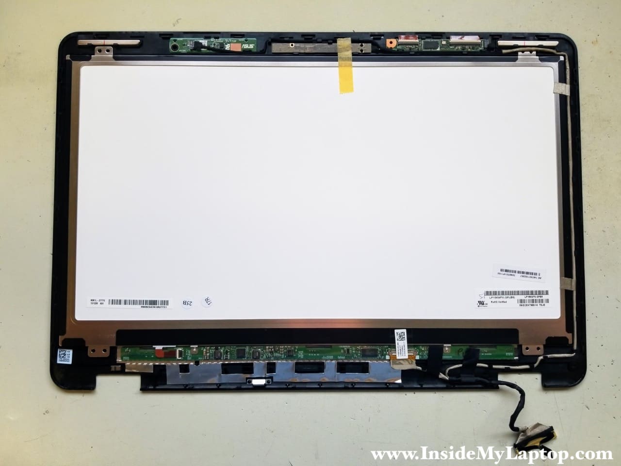
Here’s the LCD screen/digitizer assembly.
The LCD screen is glued to the back side of the front bezel frame and can be removed relatively easy.
The digitizer, on the other hand, is glued to the front side of the bezel and removing it can be a real pain, very similar to replacing cracked glass on MacBook Pro.
After some consideration, I decided to replace the entire LCD/digitizer assembly as it shown on the following picture.
IML Tech
Replacement keyboard assembly for Asus Q553 Q553U Q553UB available here:
https://amzn.to/36JOb8b
lemin
this is what I needed!!! sharing knowledge is a powerful tool so keep posting I will bookmark this for future reference.
sam_t
I want to change the hard drive of my q533. Do you know what size the torx screw is for the outer case?
Shahid
Hello, Are you able to provide me the part number of Asus Q553U touch screen digitizer.
Your help will be appreciated .
Thank You
IML Tech
Shahid, I don’t know the part number but if you search on eBay for “Asus Q553U touch screen digitizer” you will find many different options available. Hope it helps.