In this guide I explain how to disassemble an Asus Q405U (model Q405UA-BI5T5) laptop. You can use this guide for replacing the battery, upgrading the hard drive, adding more memory or any other repair that requires laptop disassembly.
Some of the design features of this model:
– The battery is mounted inside the laptop case and cannot be easily removed.
– The keyboard is permanently attached to the top case.
– The motherboard has one memory expansion slot but it’s located on the hidden side of the motherboard.
– The motherboard has a M.2 slot for SSD upgrade but it’s located on the hidden side of the motherboard.
For Asus Q405U you will need only three basic tools: Phillips screwdriver #0, tweezers and case opener tool.
STEP 1.
Remove all screws from the laptop base. Seven screws color-coded in red are longer than other four screws color-coded in green.

STEP 2.
Insert a thin metal case opener tool between the laptop base and top case assembly. Pry up the base to separate it from the top case. There are many hidden latches fastening to parts to each other.

STEP 3.
Continue separating the top case from the base assembly.

STEP 4.
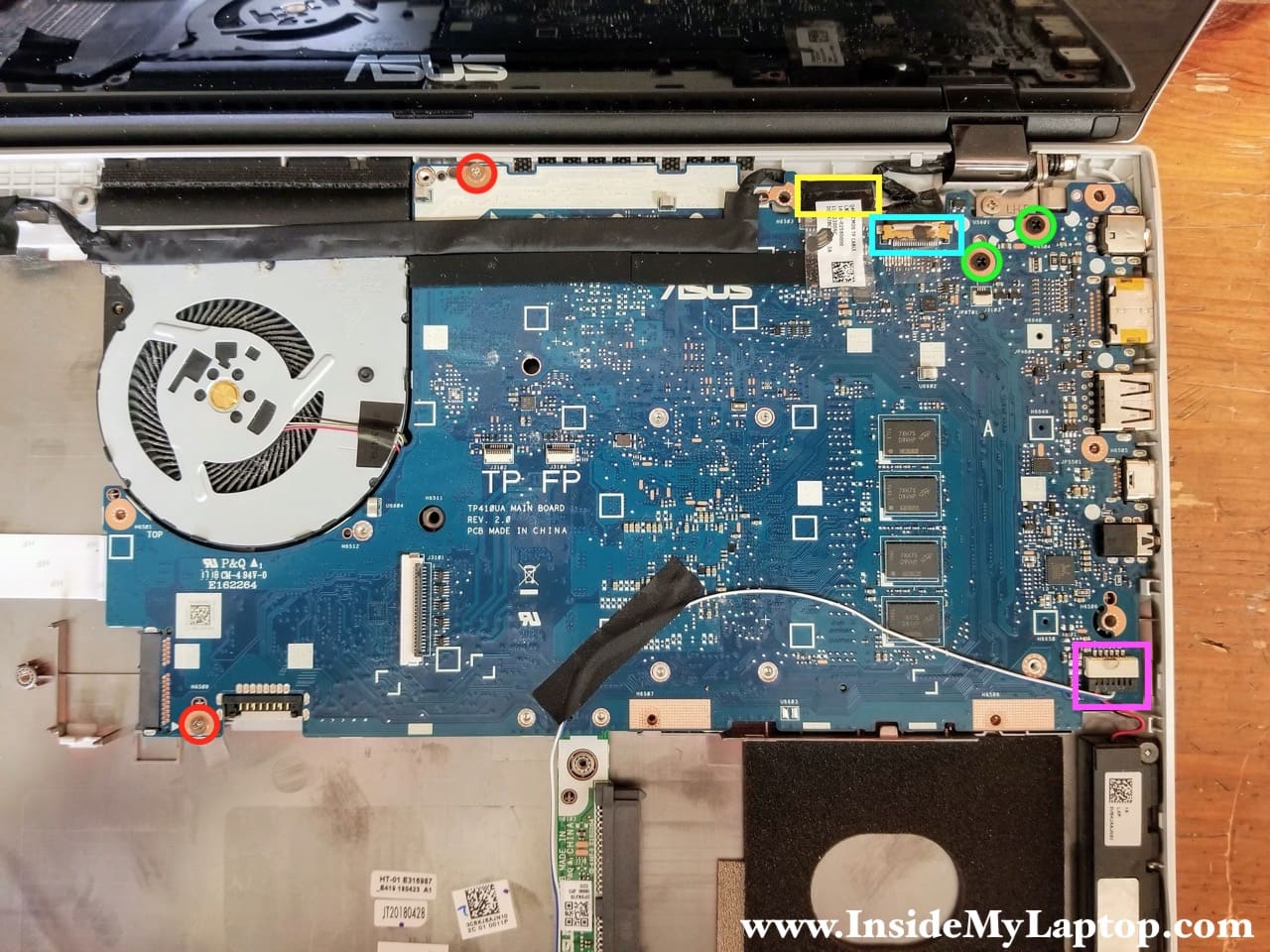
Be careful. There are four cables connecting the top case to the motherboard.
Before removing the top case completely it’s necessary to disconnect the following color-coded cables:
– Keyboard cable (orange).
– Trackpad cable (yellow).
– Finger print cable (blue).
– Keyboard backlight cable (green).
You will have very limited space to disconnect all these cables.

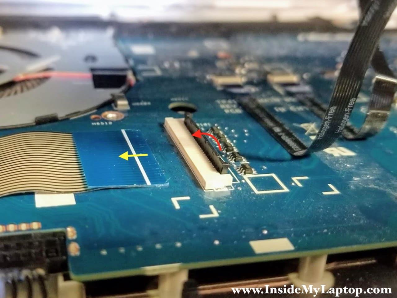
First, disconnect the keyboard cable. Unlock the connector by lifting up the locking tab at a 90 degree angle (red arrow) and pull the cable out (yellow arrow).
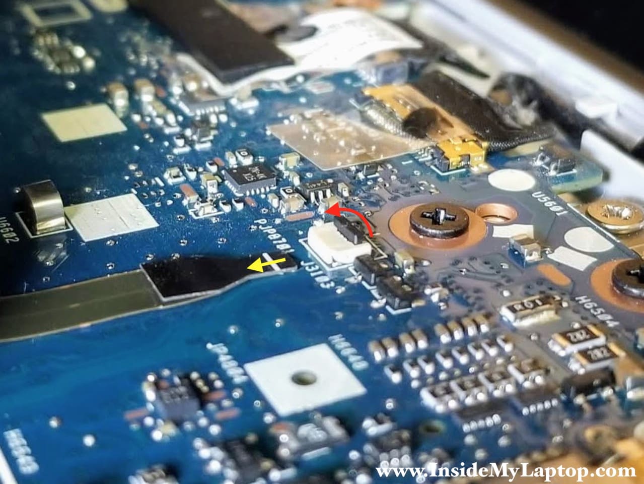
Second, disconnect the keyboard backlight cable – the smallest connector on the board.
Third, disconnect the finger print cable and trackpad cable.

STEP 5.
Now you can remove the top case assembly completely.

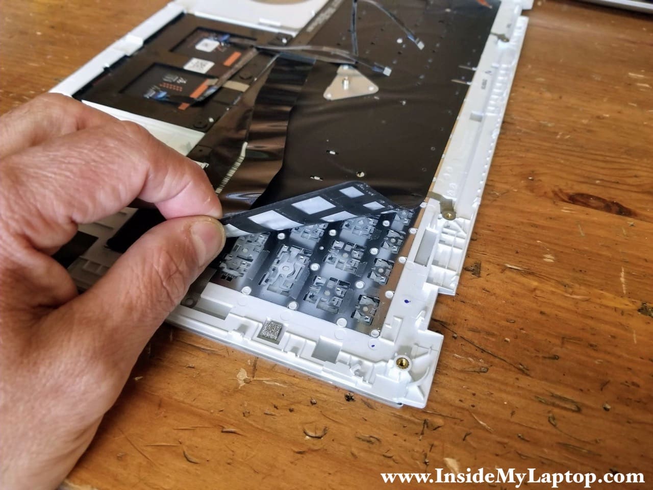
Here’s the other side of the top case assembly.

As I mentioned at the beginning of this guide, the keyboard on an Asus Q405U laptop is permanently riveted to the top case. It’s not easy to replace just the keyboard.
STEP 6.
Before taking it apart any further, don’t forget to disconnect the battery.
The wireless card antenna cables are running over the battery. We’ll remove the battery later in the guide, after we disconnect the wireless antenna cables.

Here’s how to disconnect the battery. Lift up the battery connector and unplug it from the motherboard.
WARNING! Do not use a screwdriver for that. You can accidentally short the battery connector pins and damage the motherboard. Use a plastic pry tool instead or finger nails.

STEP 7.
Remove five screws securing the hard drive caddy. Two screws on the left are covered by an aluminum shield which has to be removed too.

STEP 8.
Lift up the right side of the hard drive assembly and pull it to the right to disconnect from the SATA connector board.
My opinion about the hard drive: It’s beyond my understanding why in 2018 (when SSDs are dirt cheap) Asus used a regular 2.5″ spinning hard drive in this laptop. Just doesn’t make sense.
Upgrading this drive to solid state drive will speed up the laptop significantly.

STEP 9.
Disconnect both antenna cables from the wireless card. Lift up each connector to un-snap it from the Wi-Fi card.

STEP 10.
Remove one screw securing the Wi-Fi card and pull it out.

STEP 11.
Remove four screws securing the battery.
Un-tape Wi-Fi antenna cables from the battery and move them aside.
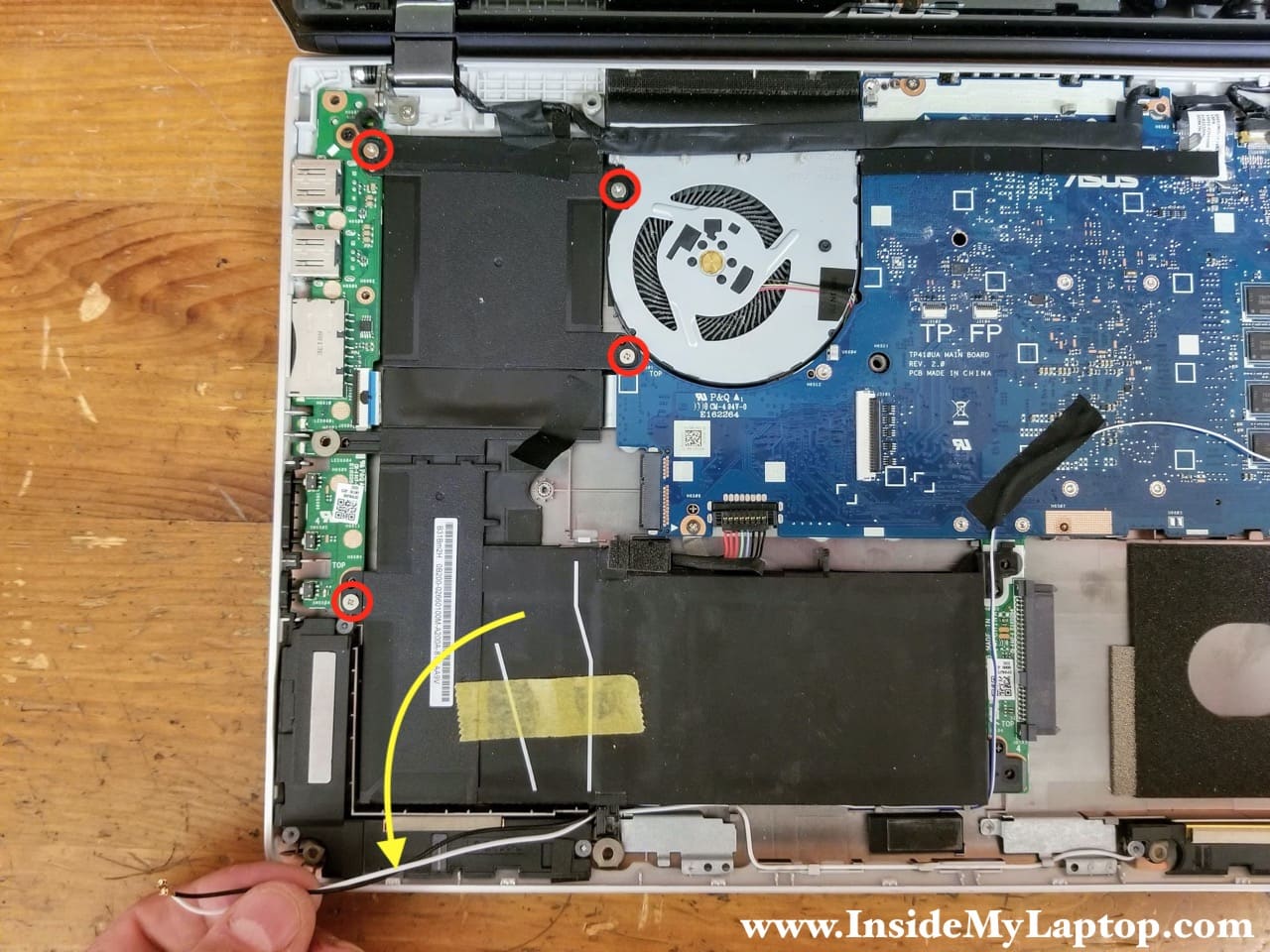
STEP 12.
Lift up the left side of the battery to separate it from the base assembly.

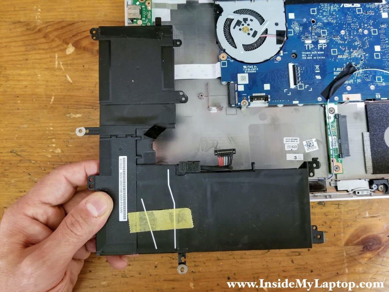
STEP 13.
Remove the battery.
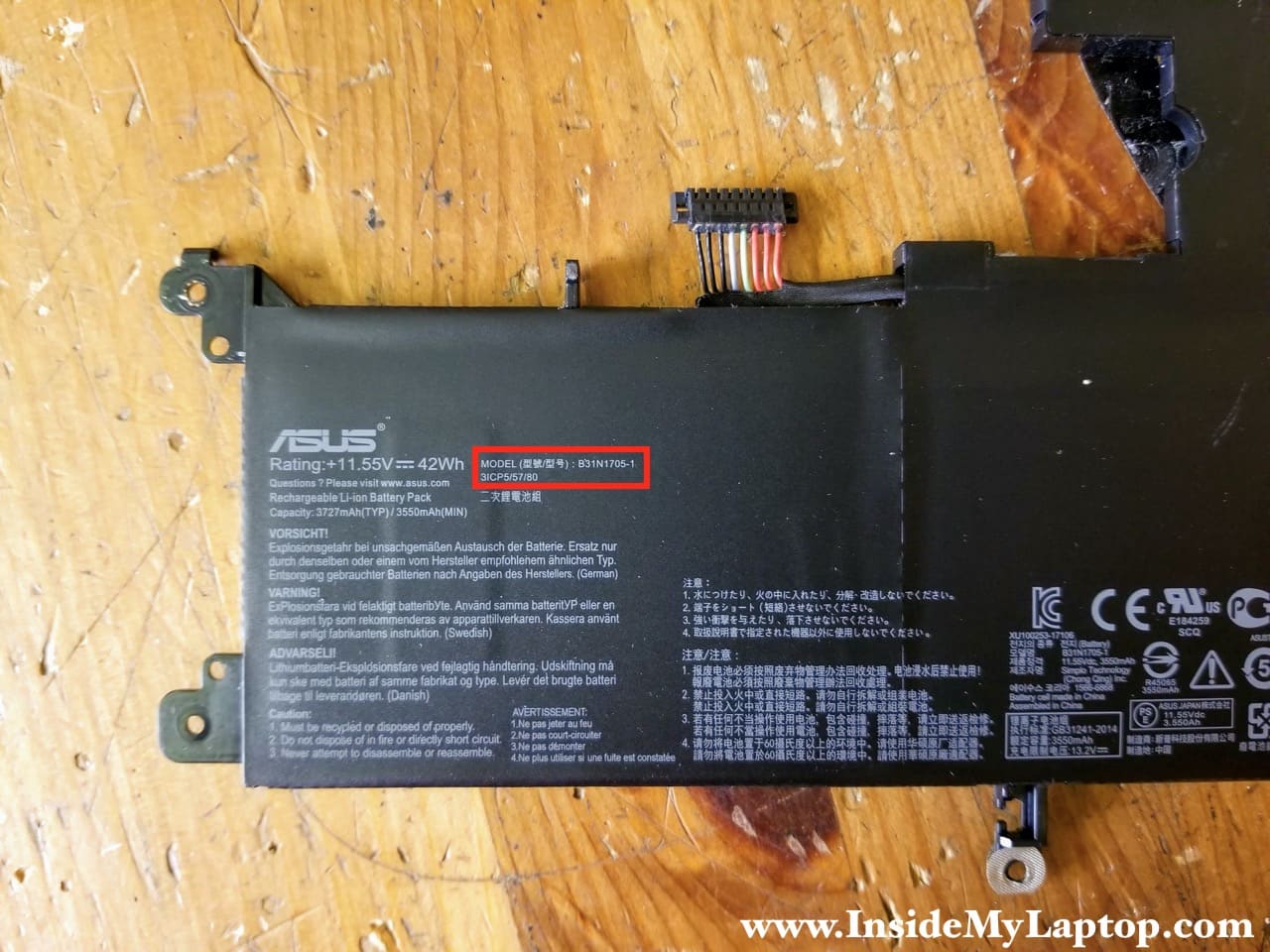
Asus Q405U (Q405UA-BI5T5) battery model: B31N1705-1.
STEP 14.
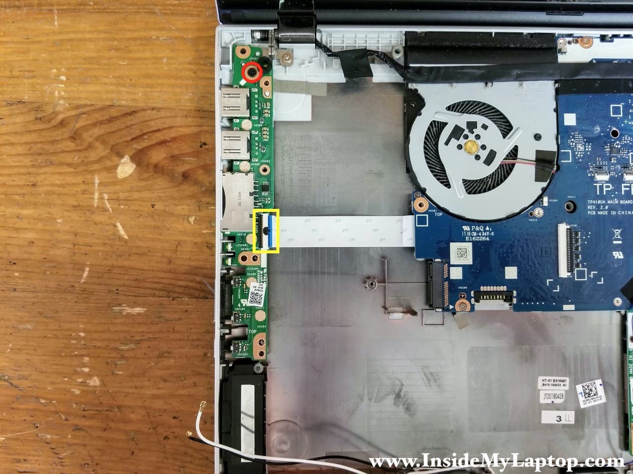
Remove one screw securing the I/O board and disconnect the I/O board cable.
On the I/O board you will find: two USB ports, SD card reader port, battery charge and status LED lights, volume control buttons and power button.
STEP 15.
Lift up and remove the I/O board.

STEP 16.
Remove four screws securing the motherboard. Two silver screws on the left (red) are shorter than two screws (green) on the right.
Disconnect two display cables (yellow and green) and one speaker cable (pink).
Here’s how to disconnect the first display cable with a plastic base.
Peel off clear sticky tape securing the connection and pull the cable out.
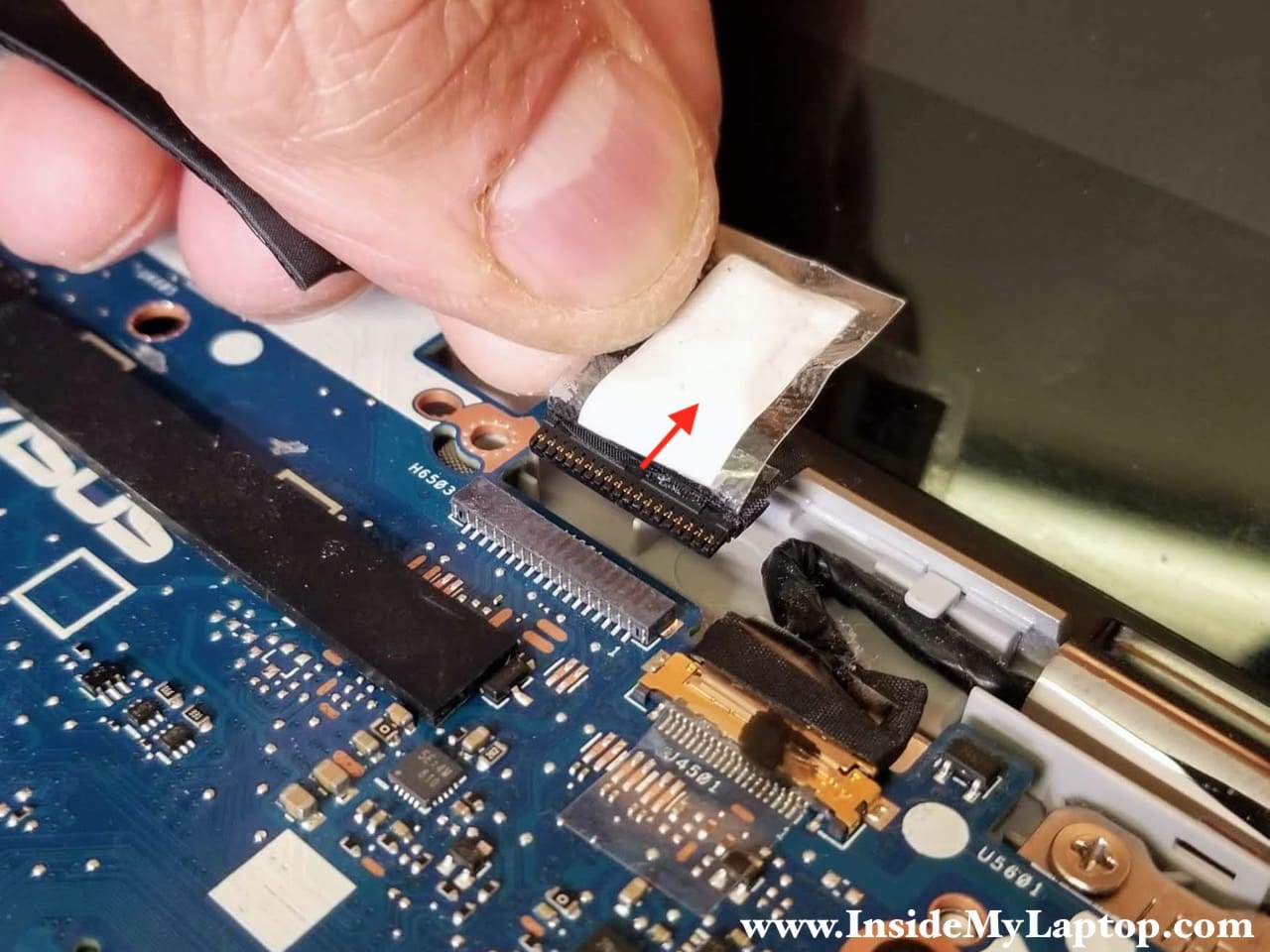
Disconnect the second display cable with a metal base the same way.

STEP 17.
Separate the motherboard from the laptop base.

STEP 18.
Remove the motherboard. The hard drive SATA connector board is attached to the motherboard.

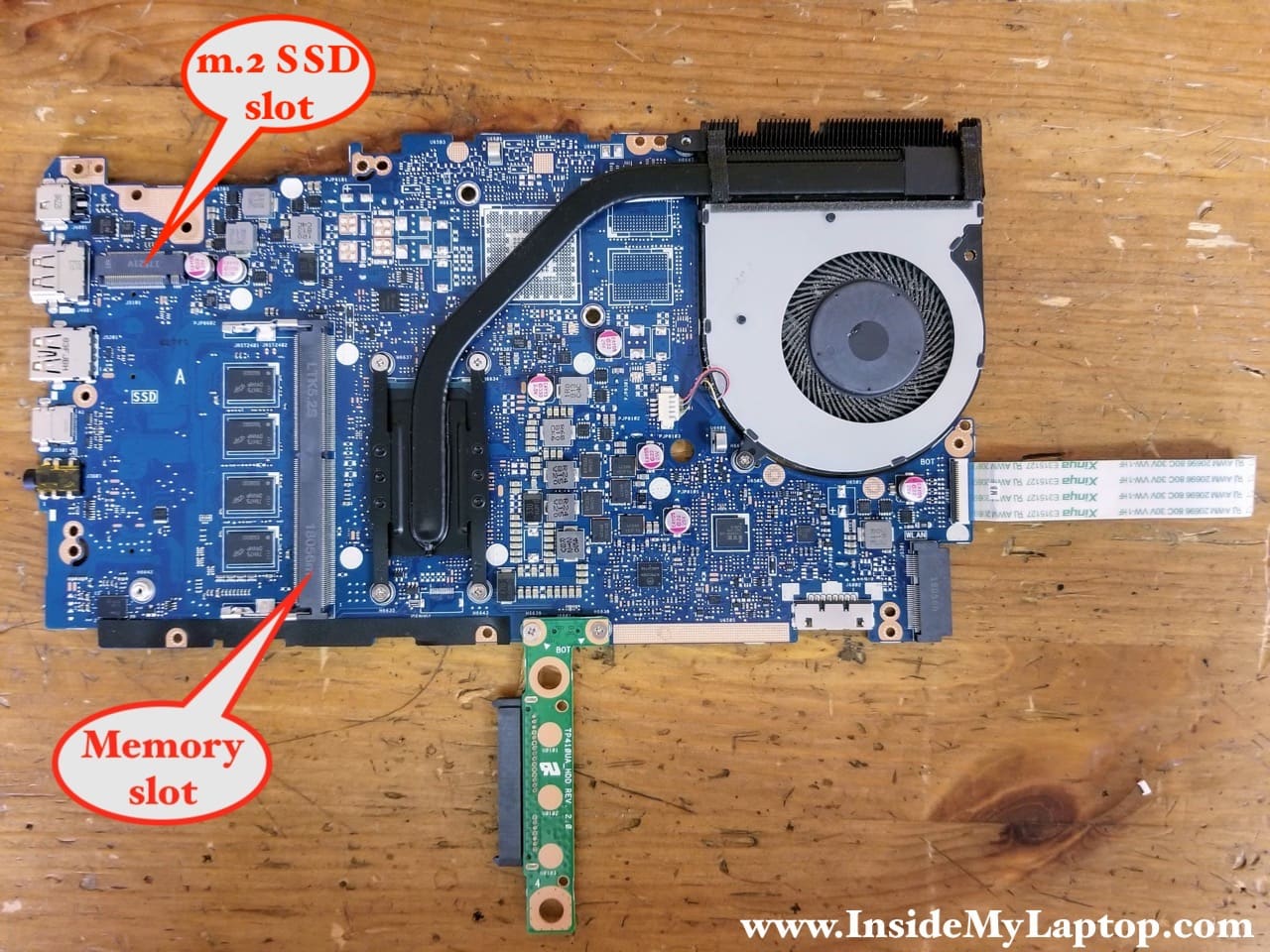
Here’s the other side of the motherboard. The power connector is soldered to the motherboard.
Finally, you can access the memory expansion slot and upgrade RAM if necessary.
You can add up to 8GB 2400MHz DDR4 SDRAM memory module in the open slot.
The M.2 slot for SSD upgrade also located on this side of the motherboard (fits SSD size 2080).
STEP 19.
Remove two screws securing the left and right display hinges to the base assembly.

STEP 20.
Now you can separate the display panel from the laptop base.

HumptyDooDumpty
Your guide and pics were a lifesaver today, Thank You!
Njoroge
very informative piece. Thanks . It appears the display is replaced as a single unit. just wondering.