In this guide I show a full disassembly of an Asus F556U series laptop. To be precise, I’m taking apart an Asus F556UA-UB71 model (made in 2016) and most likely you can use this guide Asus F555L and some other models too.
There will be two Asus F556U disassembly guides. In this one I explain how to take apart the laptop base and in the next one I explain how to take apart the display panel and remove the LCD screen.
I will be using a Phillips screwdriver #0, fine tweezers and a plastic spudger.
Memory module removal
Asus F556U series laptop has 4GB non-removable memory soldered to the motherboard and one memory slot which can be easily accessed through the RAM cover on the bottom. It can take up to 8GB DDR4-2400 SODIMM in the empty slot. Total RAM for this model is 12GB (4GB onboard and 8GB removable).
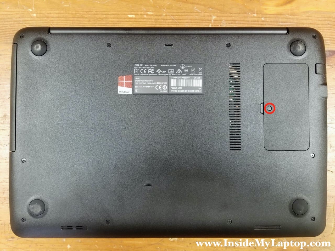
STEP 1.
Remove one screw (hidden under a cover) securing the memory cover. Pry up and remove the memory cover.
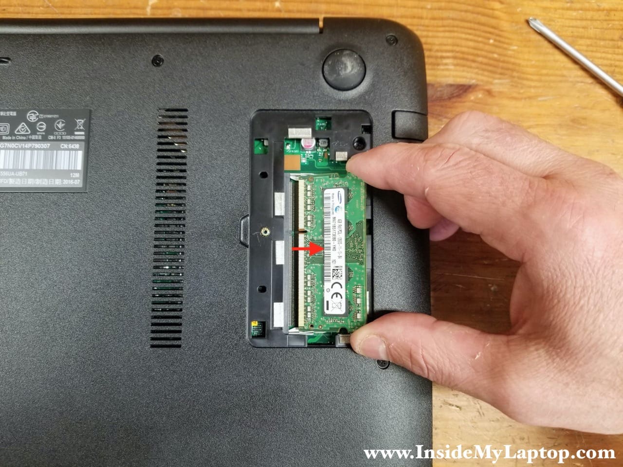
STEP 2.
Remove the memory module and replace it with a larger capacity module if necessary.
Base cover and battery removal
STEP 3.
Remove all screws securing the base cover to the top case.
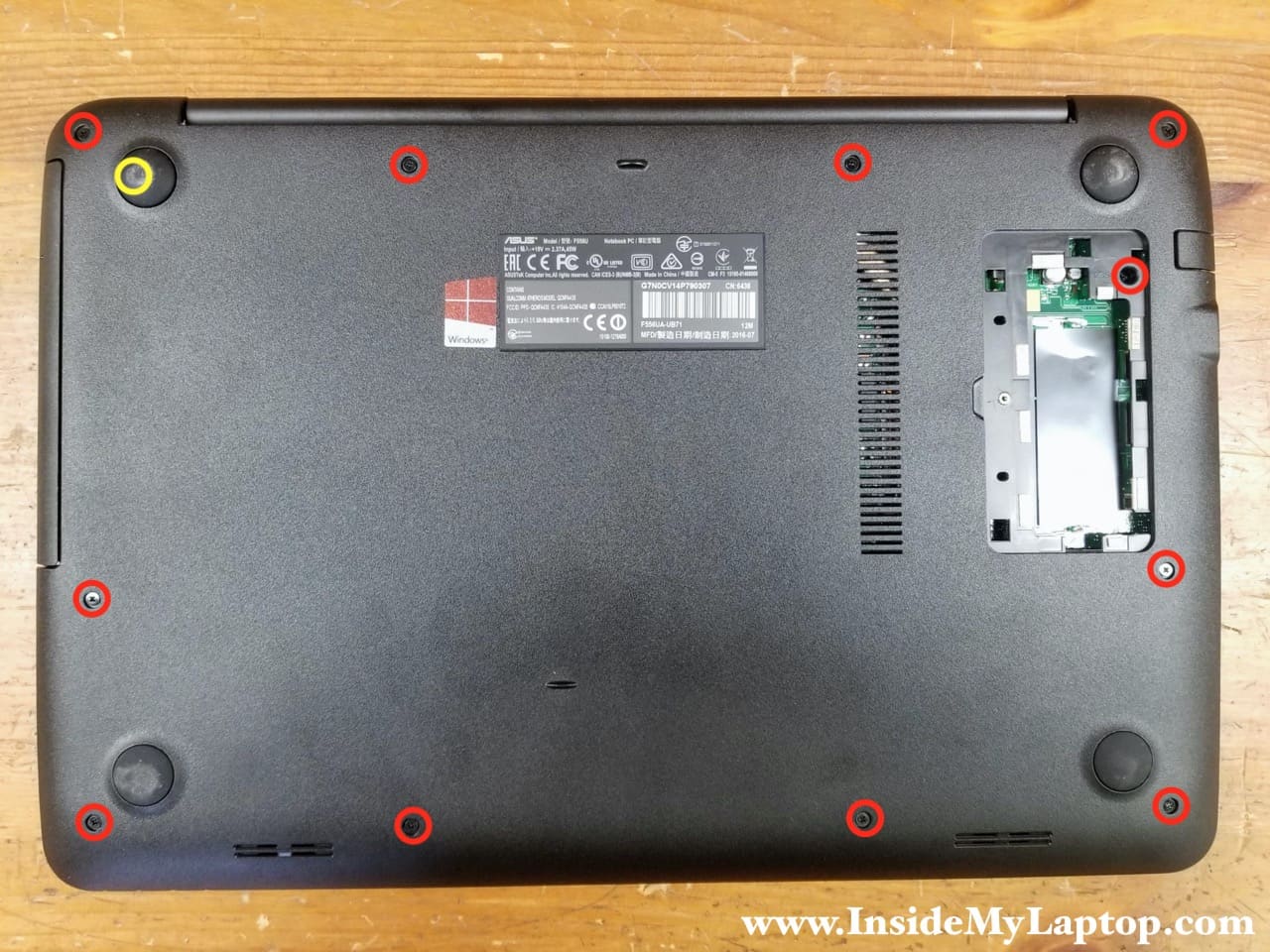
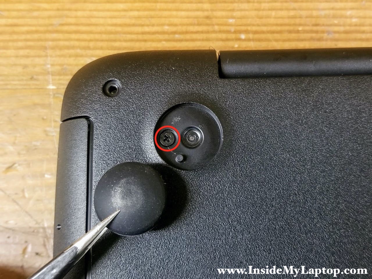
One of the screws is hidden under the bottom foot (closest to the optical drive). Remove the bottom foot (self-adhesive) in order to access the hidden screw.
For some reason Asus decided to use five different types of screws on the bottom. Keep track of all removed screws, it will help a lot during the re-assembly process.
Here’s how I do it. Draw a diagram of all bottom screw locations on a piece of paper. Using a small screwdriver make holes for the screws and secure all screws on the diagram.

STEP 4.
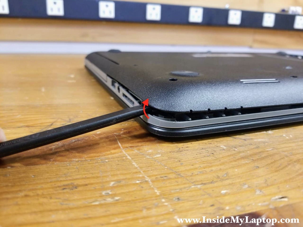
Start separating the base cover from the top case using a plastic spudger. Move the spudger along the side and try up the base cover.
STEP 5.
Continue removing the base cover with your hands. There are many hidden latches securing the base cover. You’ll have to use some reasonable force to remove the cover.

STEP 6.
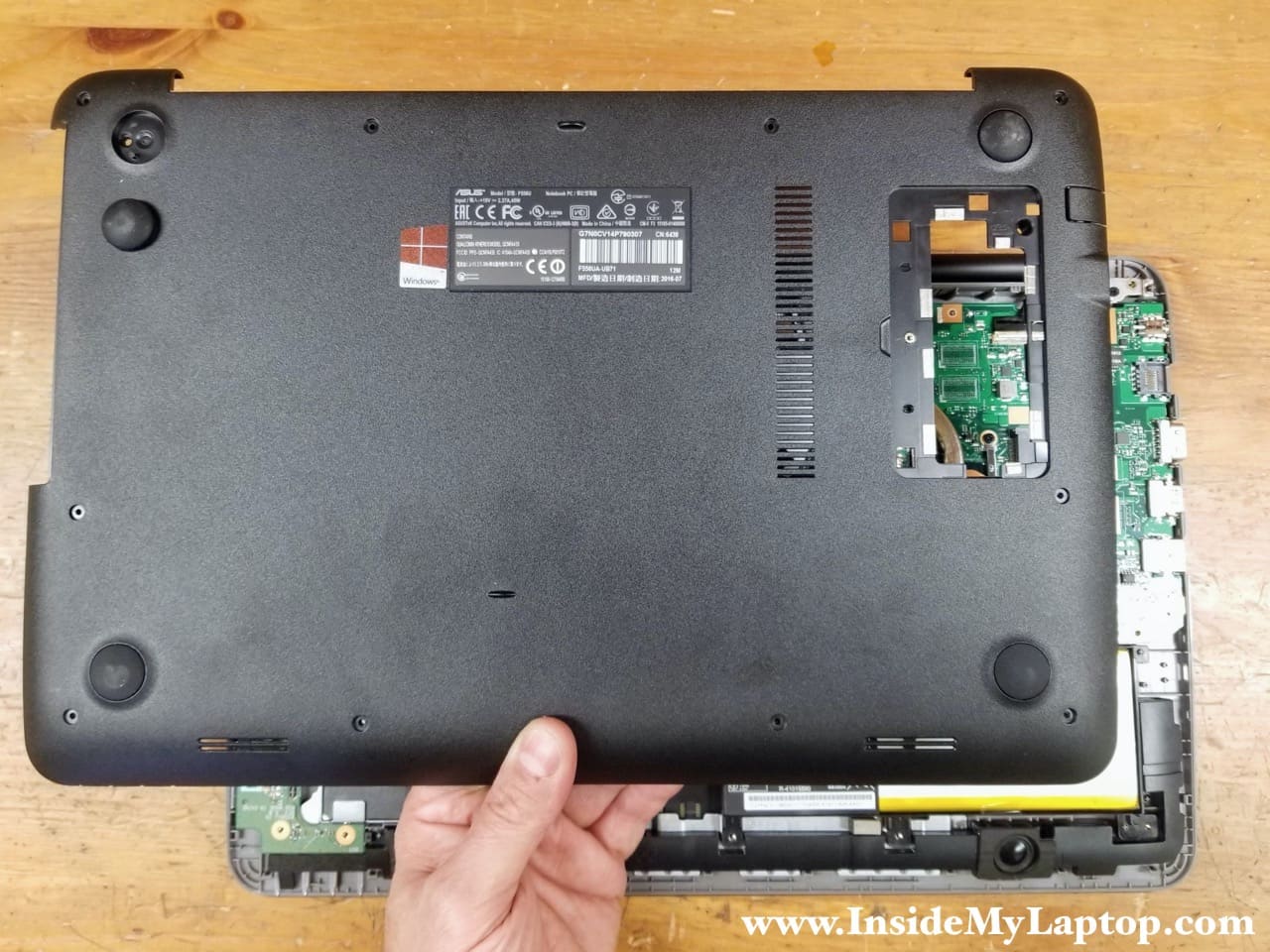
Remove the base cover completely.
STEP 7.
Remove two screws attaching the battery to the top case.

STEP 8.
Lift up and remove the battery.

Hard drive removal
The hard drive is mounted under the I/O board cable and part of the hard drive bracket is located under the I/O board. It’s necessary to remove the I/O board with the cable in order to remove the hard drive.
STEP 9.
Disconnect the I/O cable from the motherboard.
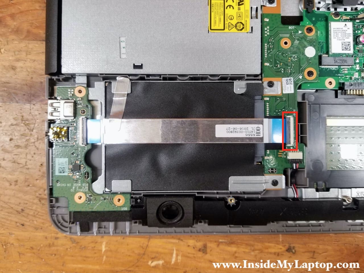
Here’s how to release the I/O cable. Lift up the locking tab (red arrow) to unlock the connector and pull the cable out.

STEP 10.
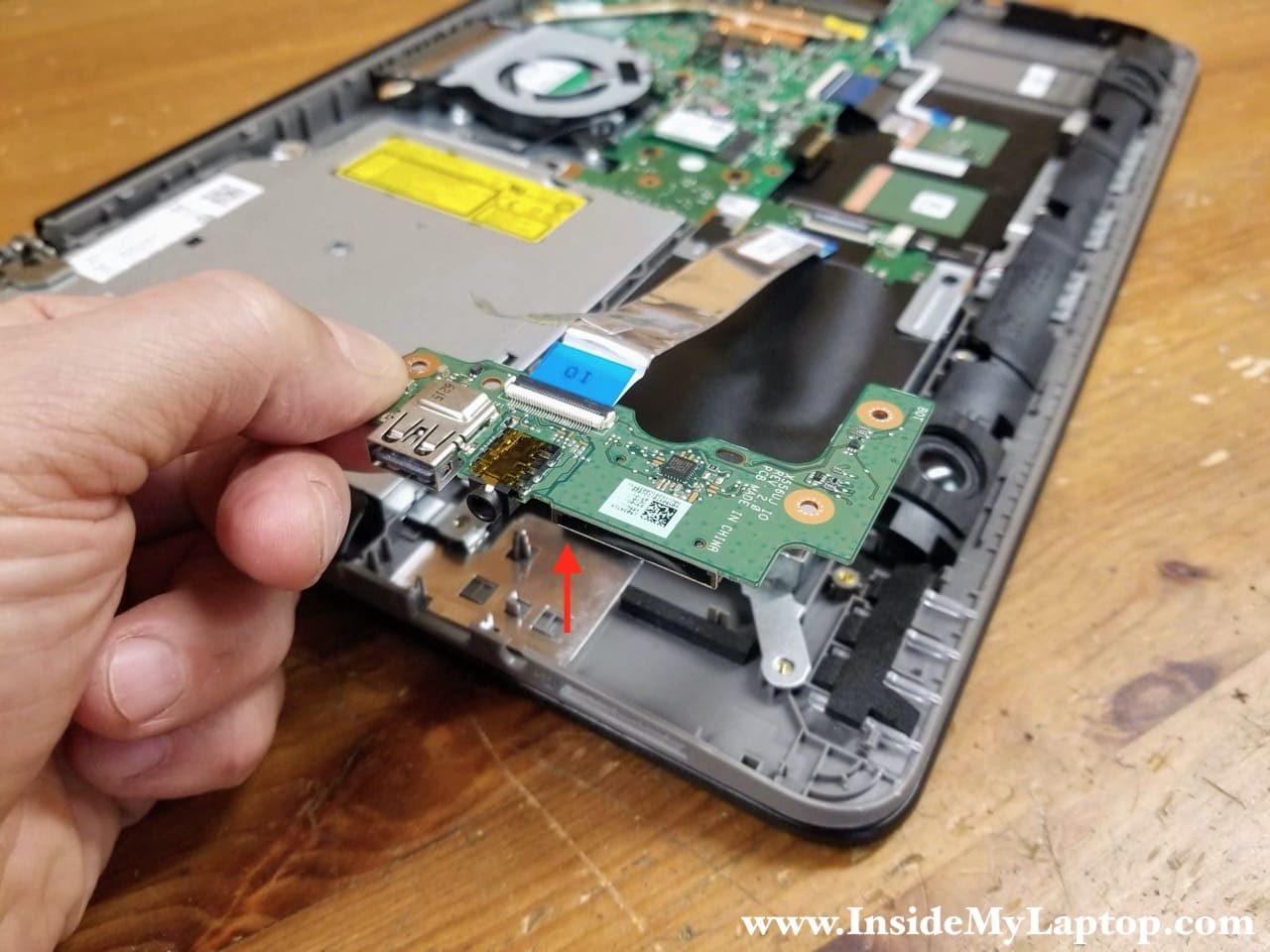
There are no screws securing the board but there is a small latch on the right side. Release the latch to separate the board from the top case.
Lift up and remove the I/O board (USB/audio jack/card reader) with the cable attached.
STEP 11.
Remove two screws securing the hard drive bracket.

STEP 12.
Lift up the left side of the hard drive and pull it away from the motherboard to disconnect from the SATA port.
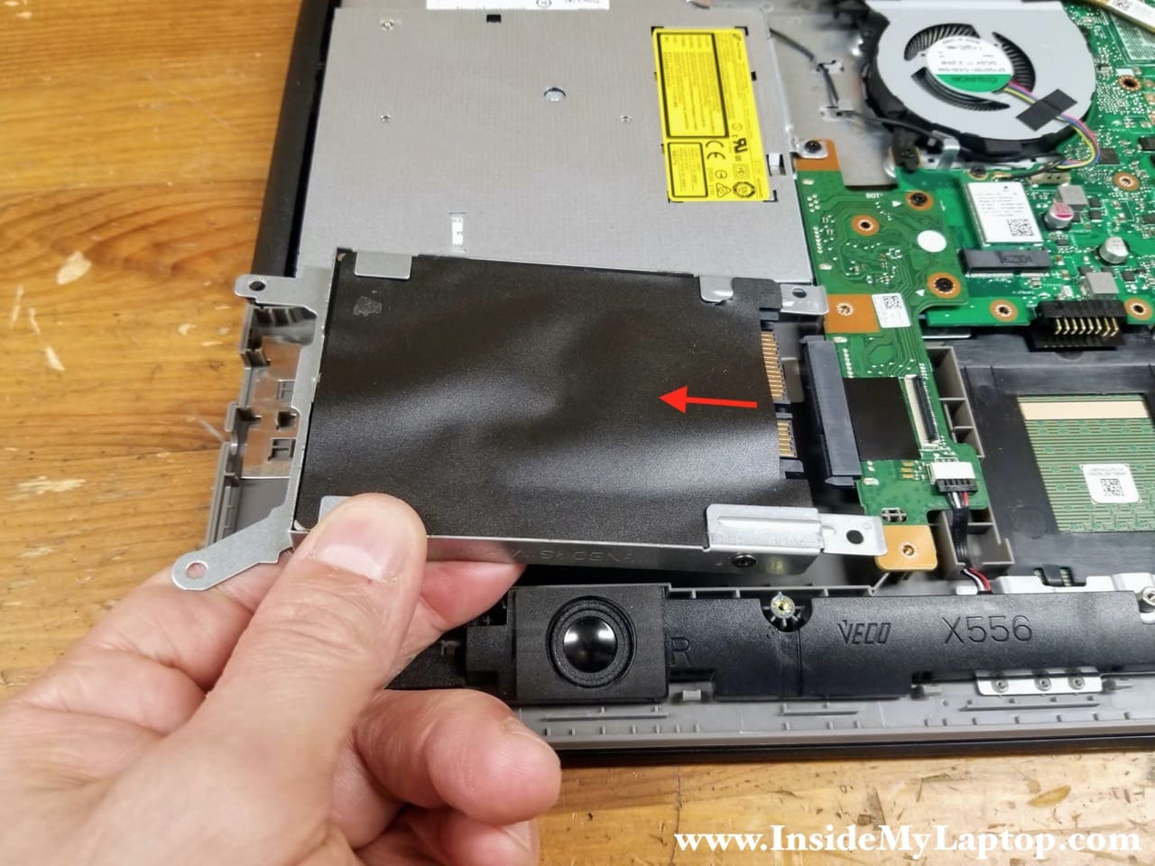
Asus F556U series laptop has a regular 2.5″ spinning (slow) hard drive installed. I would strongly recommend upgrading it to a 2.5″ solid state drive which will make your laptop much faster.
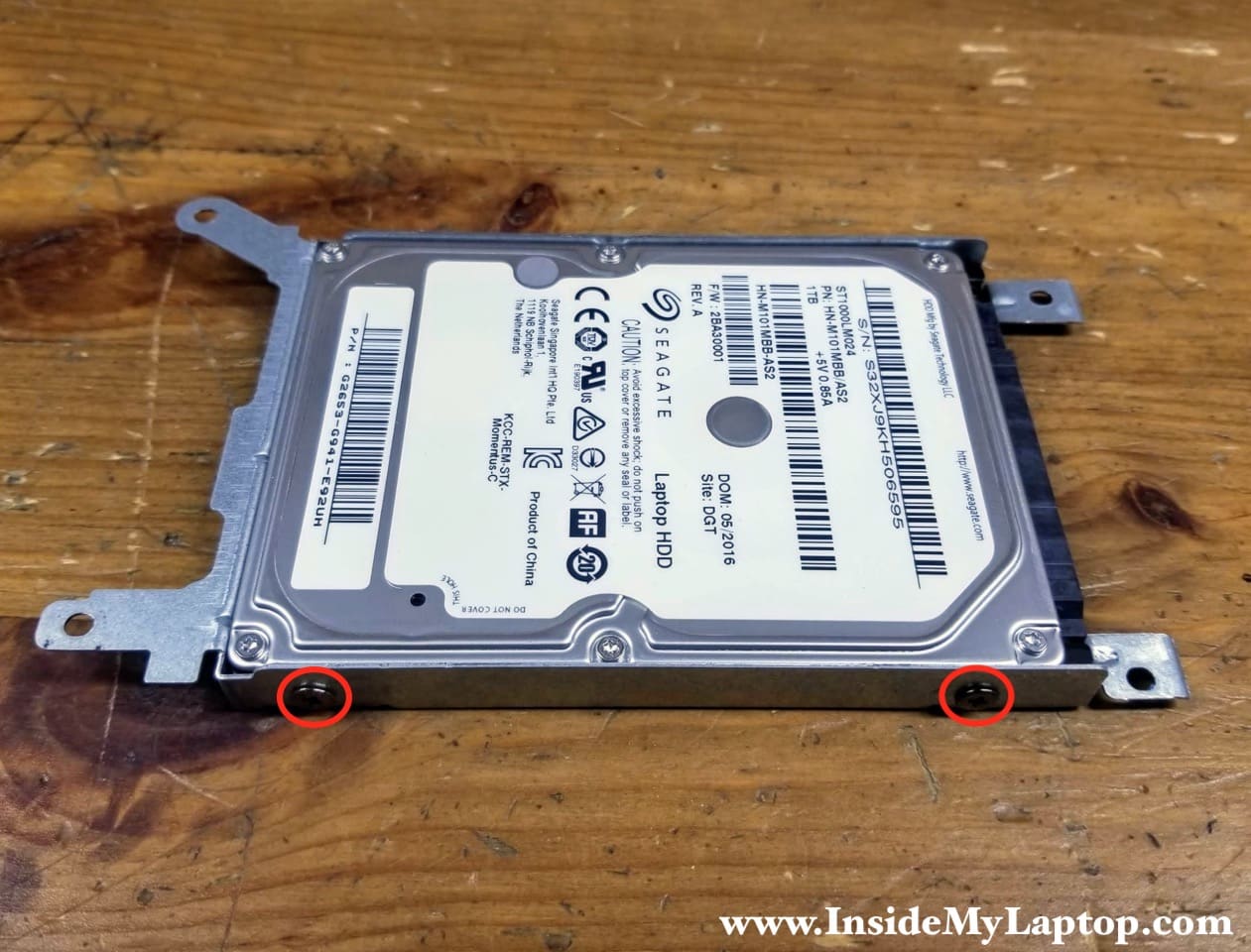
If you decide to upgrade to a solid state drive, you’ll have to transfer the mounting bracket to the new drive. The bracket is secured by four screws (two on each side).
Optical drive and fan assembly removal
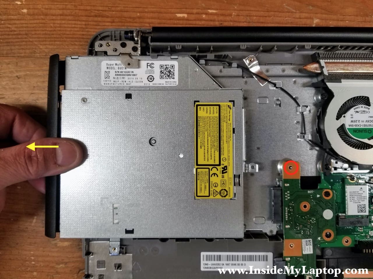
STEP 13.
Remove one screw securing the optical CD/DVD drive. Pull the optical drive out.
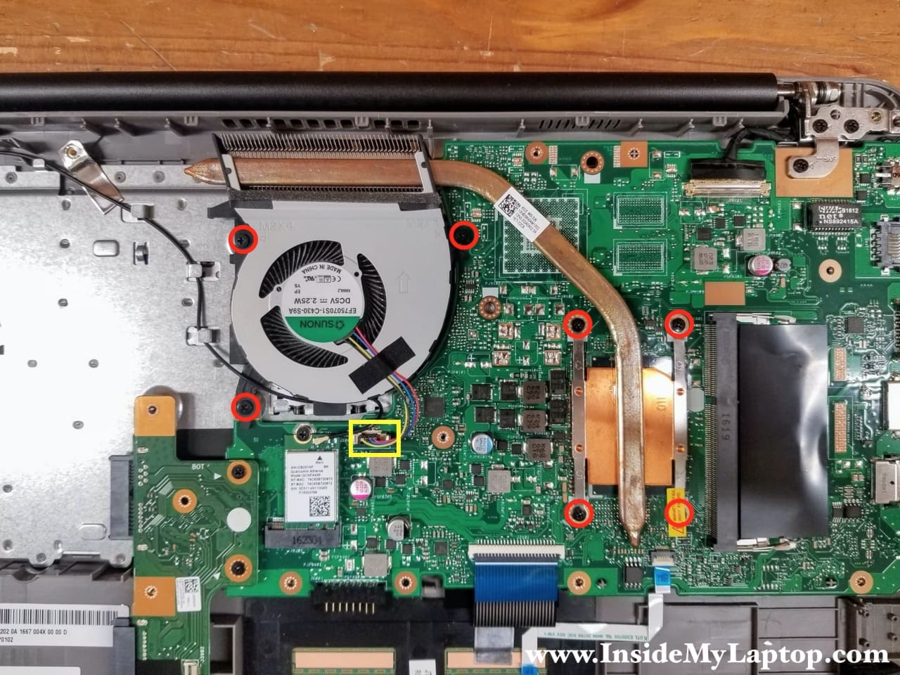
STEP 14.
Remove seven screws securing the cooling fan assembly (fan and heatsink). Disconnect the fan cable from the motherboard.
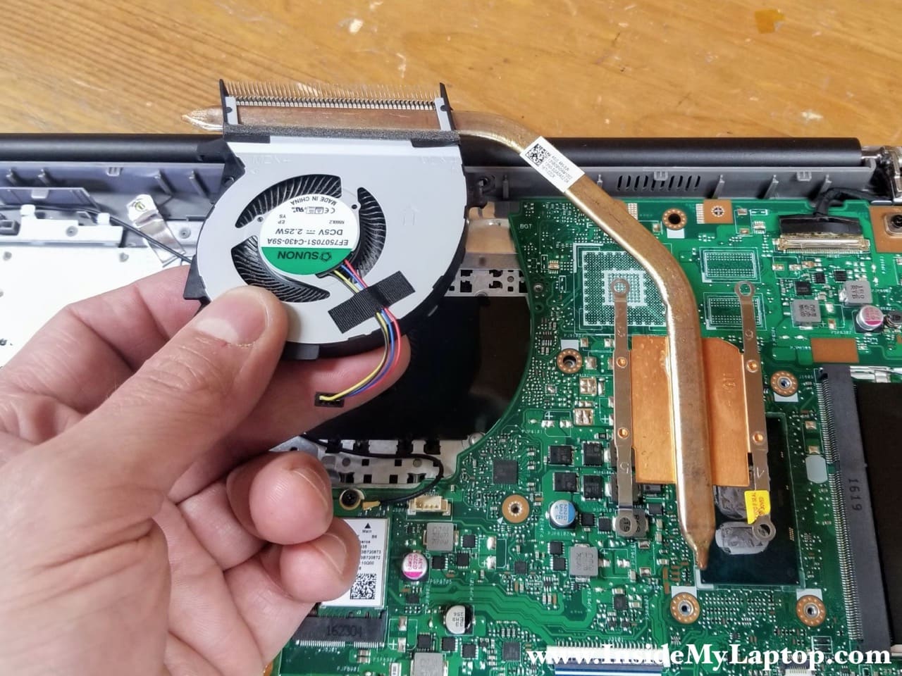
STEP 15.
Carefully separate the heatsink from the processor and remove the fan assembly.
Display panel removal
STEP 16.
Disconnect one antenna cable from the wireless card (red). Disconnect the display video cable from the motherboard (yellow).
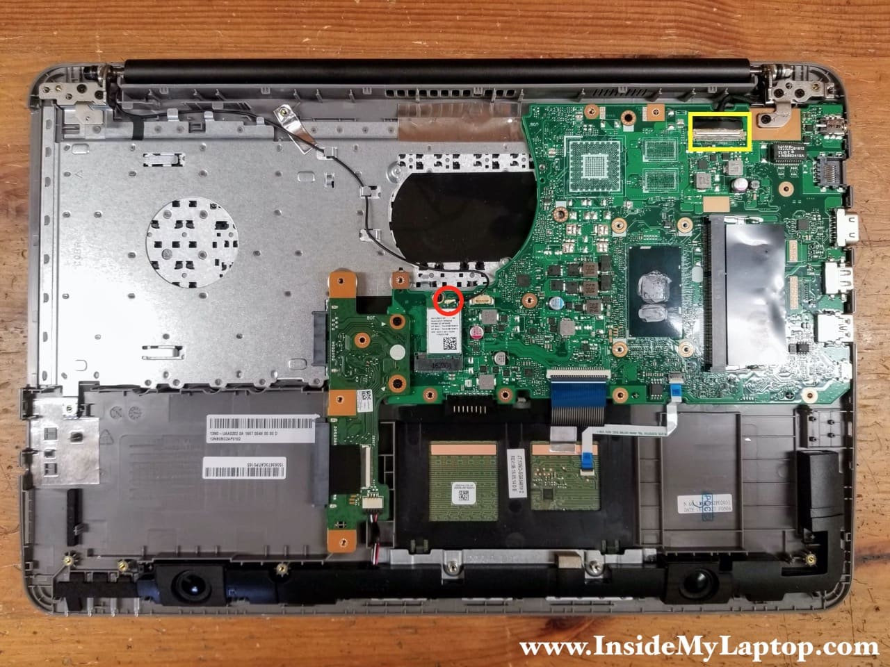
In order to disconnect the wireless card antenna cable simply lift up the cable “head” and un-snap it from the connector on the card.
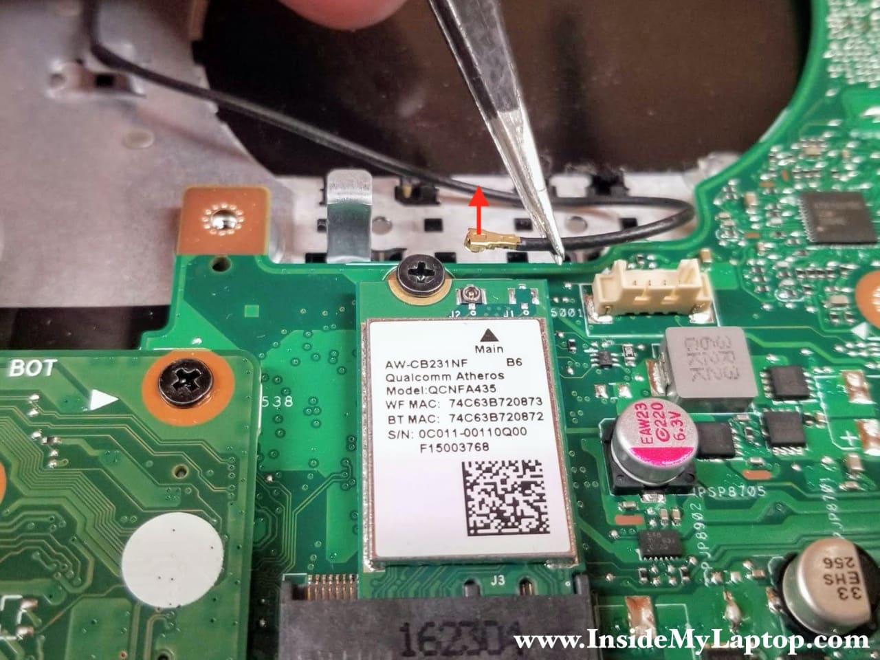
Be careful while disconnecting the display video cable. The connector looks fragile with a bunch or thin wires exposed.
Lift up clear tape securing the connection and pull the display cable out.

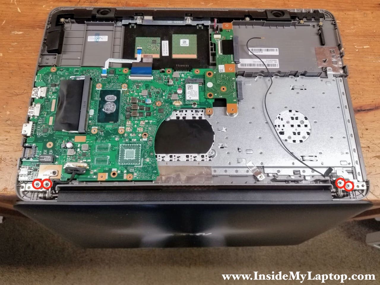
STEP 17.
Open up the display panel 90 degrees and place the laptop upside down on the edge of the desk as it shown on the following picture.
Remove four screws securing the display panel hinges.
STEP 19.
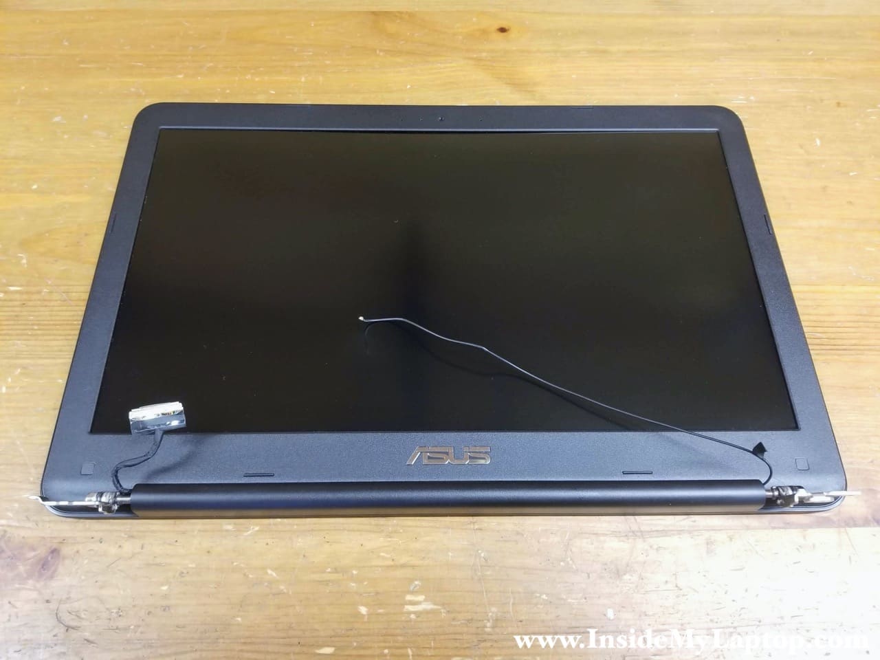
Separate the display panel from the top case assembly.
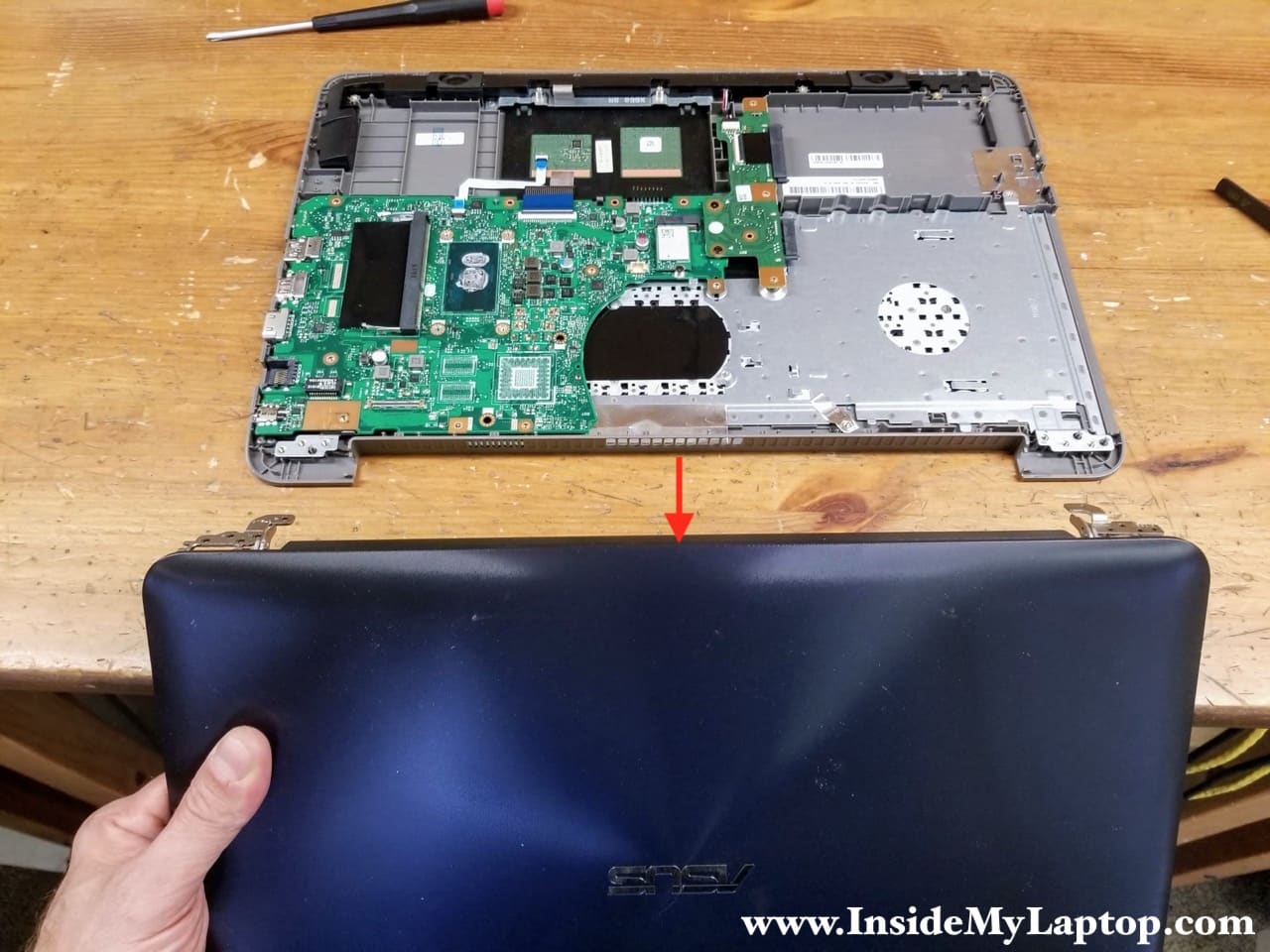
In the next guide I explain how to take apart the display panel and remove the LCD screen.
The display panel has to be removed in order to replace the screen.
Motherboard removal
STEP 20.
Remove two screws securing the optical drive and hard drive connector board.
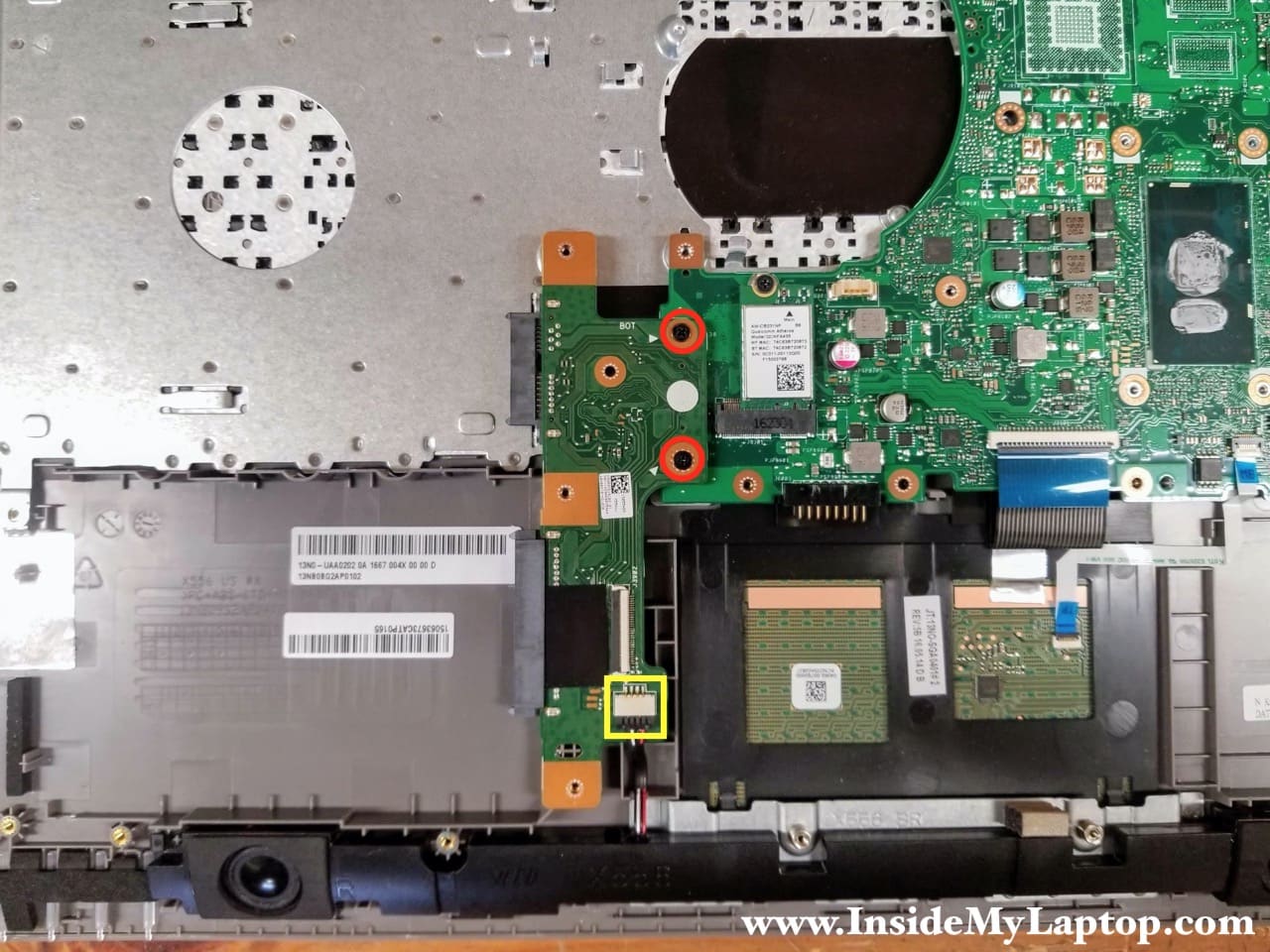
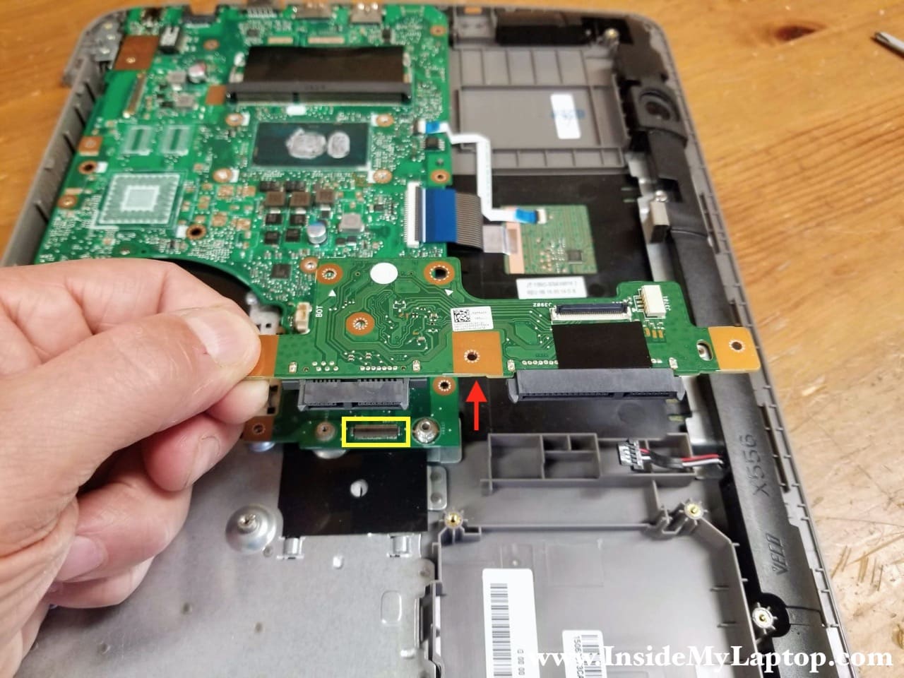
STEP 21.
Lift up the optical drive and hard drive connector board to disconnect it from the motherboard and remove it.
STEP 22.
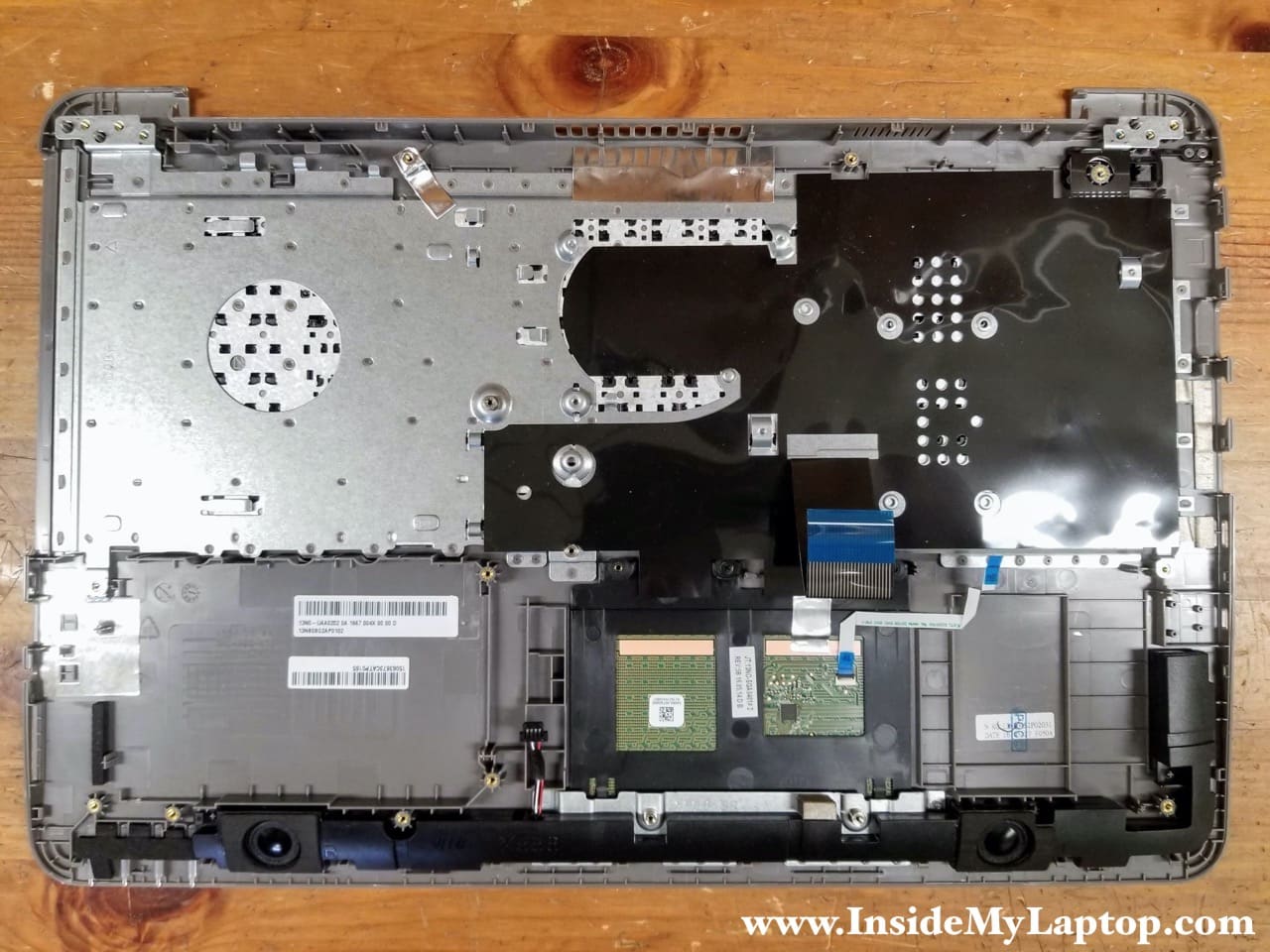
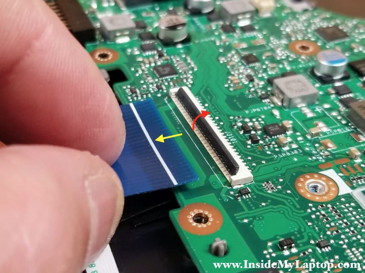
Disconnect the keyboard cable (red) and the touchpad cable (yellow) from the motherboard.
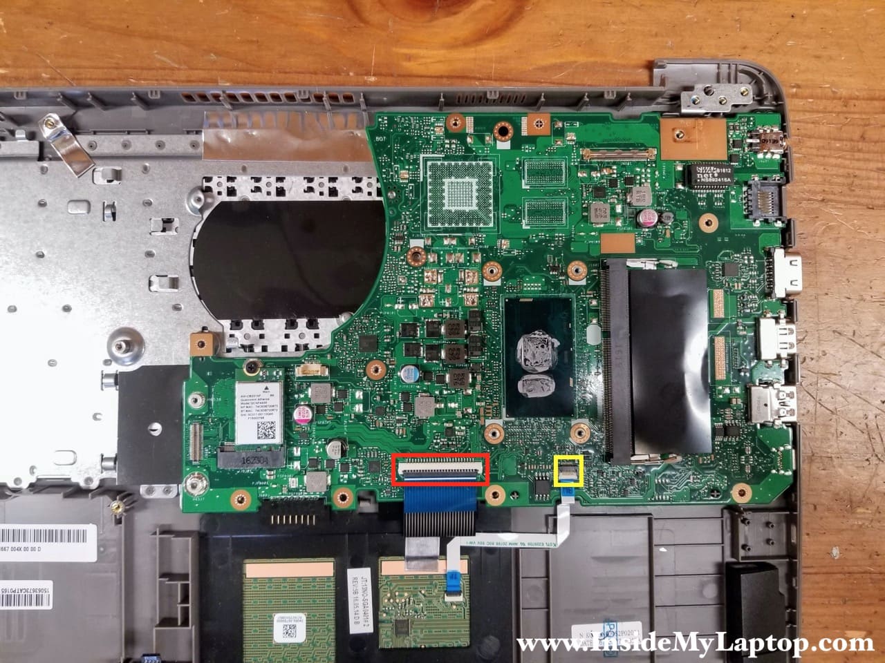
Both connectors have to be unlocked before you disconnect the cable.
STEP 23.
Lift up and remove the motherboard.
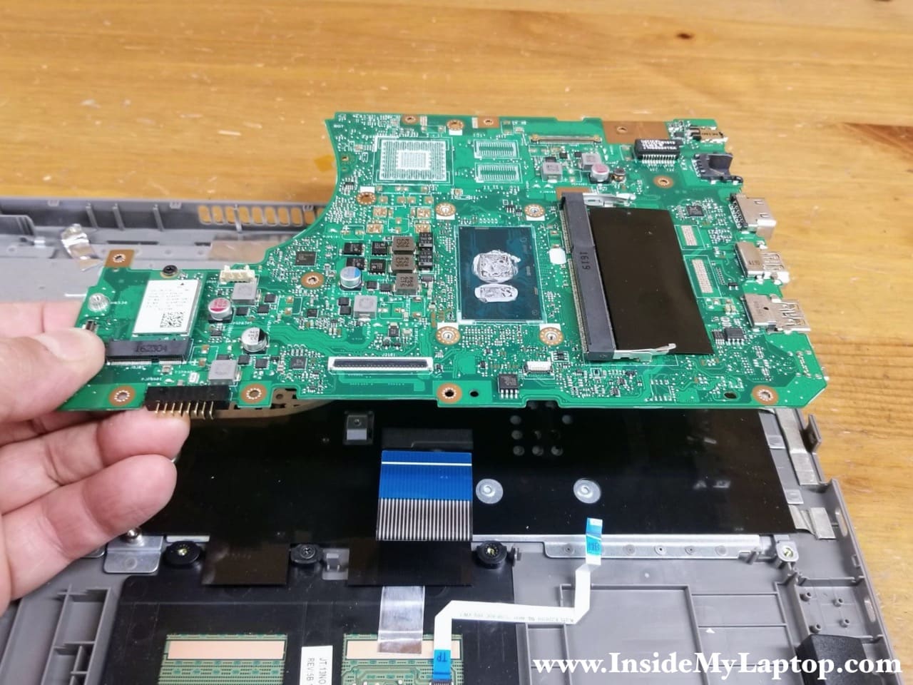
Here’s the other side of the motherboard.
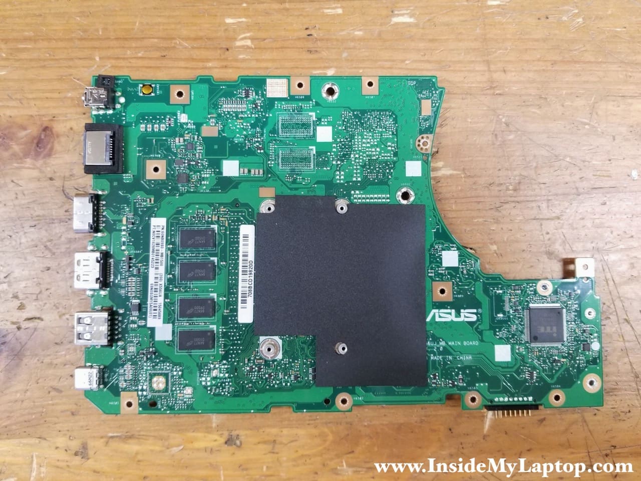
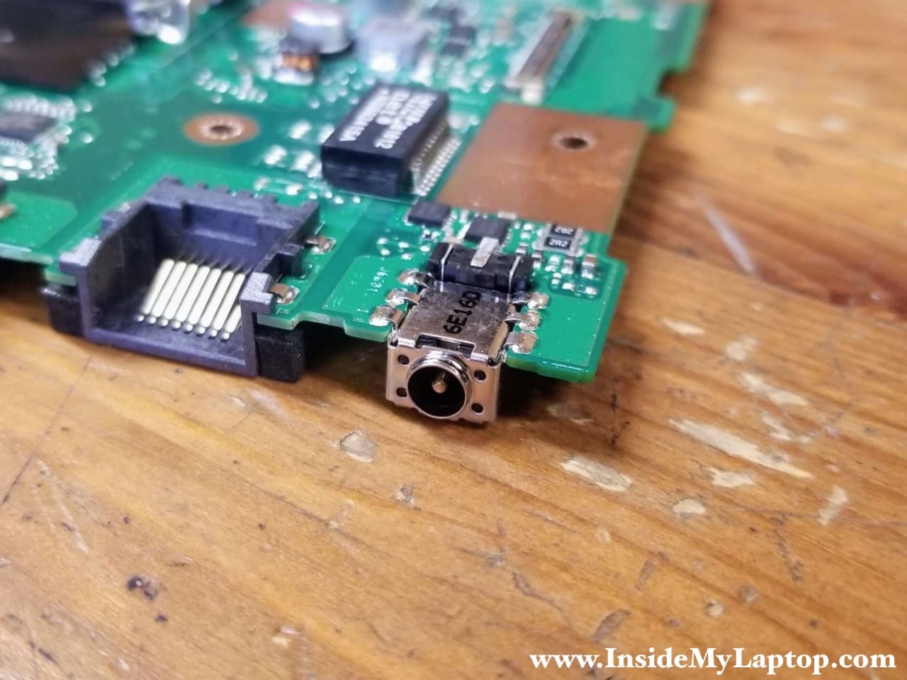
The DC power jack is soldered to the motherboard. If the DC jack fails, it has to be de-soldered from the board and replaced with a new one.
The keyboard is permanently attached to the top case. It’s possible to replace the keyboard without replacing the top case but it’s not easy. In a case of keyboard failure I suggest you replace the entire top case.
The touchpad, on the other hand, is removable.