
In this guide I show how to disassemble a Dell Inspiron 15 5565 or 5567 (model P66F) laptop. This guide is only for the laptop base disassembly. Also I will show how to remove the display panel but the LCD screen removal and replacement will be covered in the next article.
It’s possible that you can use these disassembly instructions for some other models in the Dell Inspiron 15 5000 series computer line.
For this teardown you will need the following repair tools: Phillips #1 and #0 screwdrivers, case opener tool, fine tweezers.
Base cover removal
STEP 1.
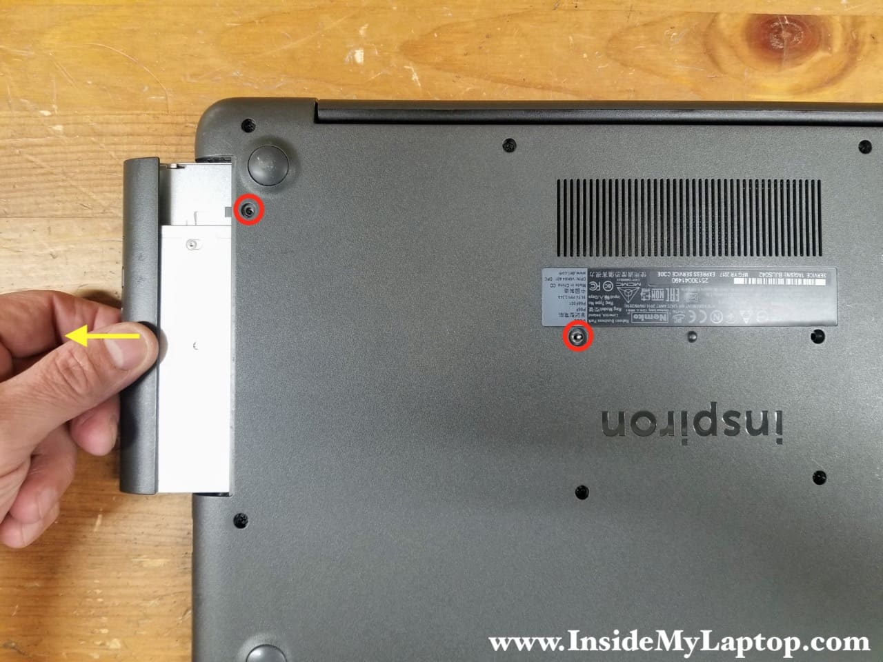
Remove two screws securing the optical drive. Pull the optical drive out.
STEP 2.
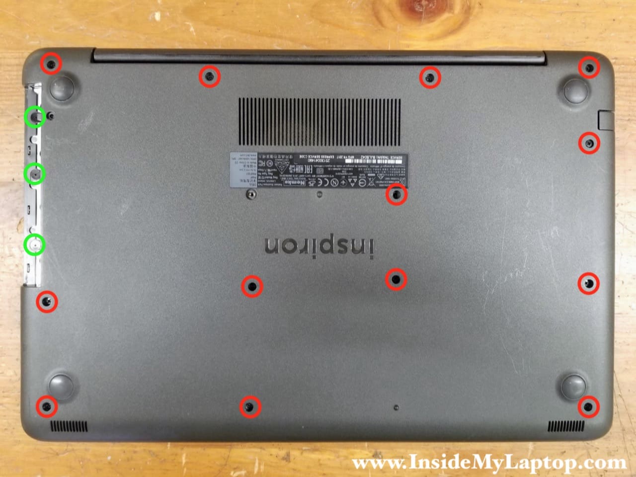
Remove all screws securing the base cover. Don’t forget three screws in the optical drive bay.
STEP 3.
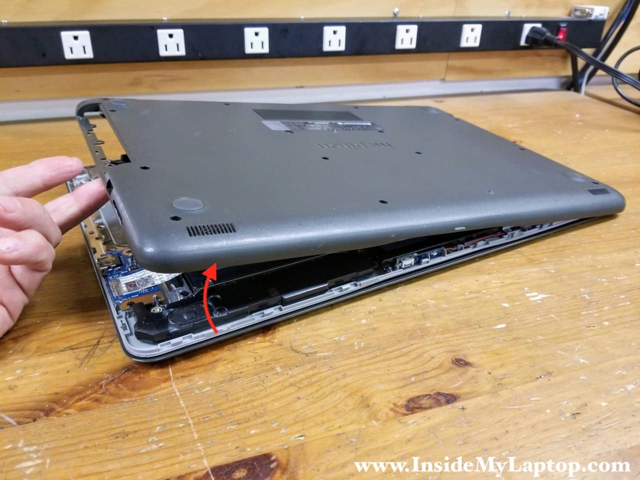
Insert the case opener tool between the palmrest and the base cover. Pry up the palmrest and start separating it from the base cover. There are multiple hidden latches attaching these two parts together.

STEP 4.
Continue removing the base cover with your hands. You will have to apply some reasonable force to remove the base cover.
Memory and hard drive removal
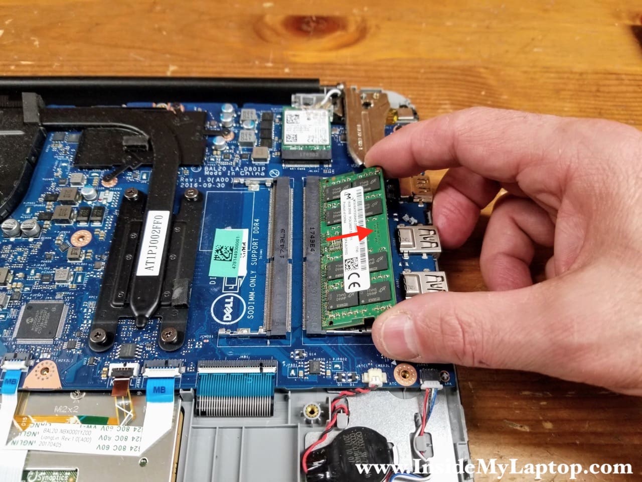
Dell Inspiron 15 5565 5567 motherboard has two memory slots available for RAM upgrade. Now you can remove and replace the memory module if necessary. You can install up to 16GB (2x8GB) DDR4-2400 SODIMM into this laptop.
The hard drive is mounted under the I/O board cable. So the I/O board and cable have to be removed first.
STEP 5.
Remove one screw securing the I/O board (USB and card reader board). Disconnect the I/O cable from the motherboard.
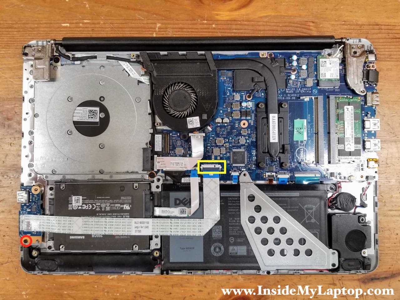
Unlock the cable connector by lifting up the locking tab (red arrow). After that you can pull the cable out.

STEP 6.
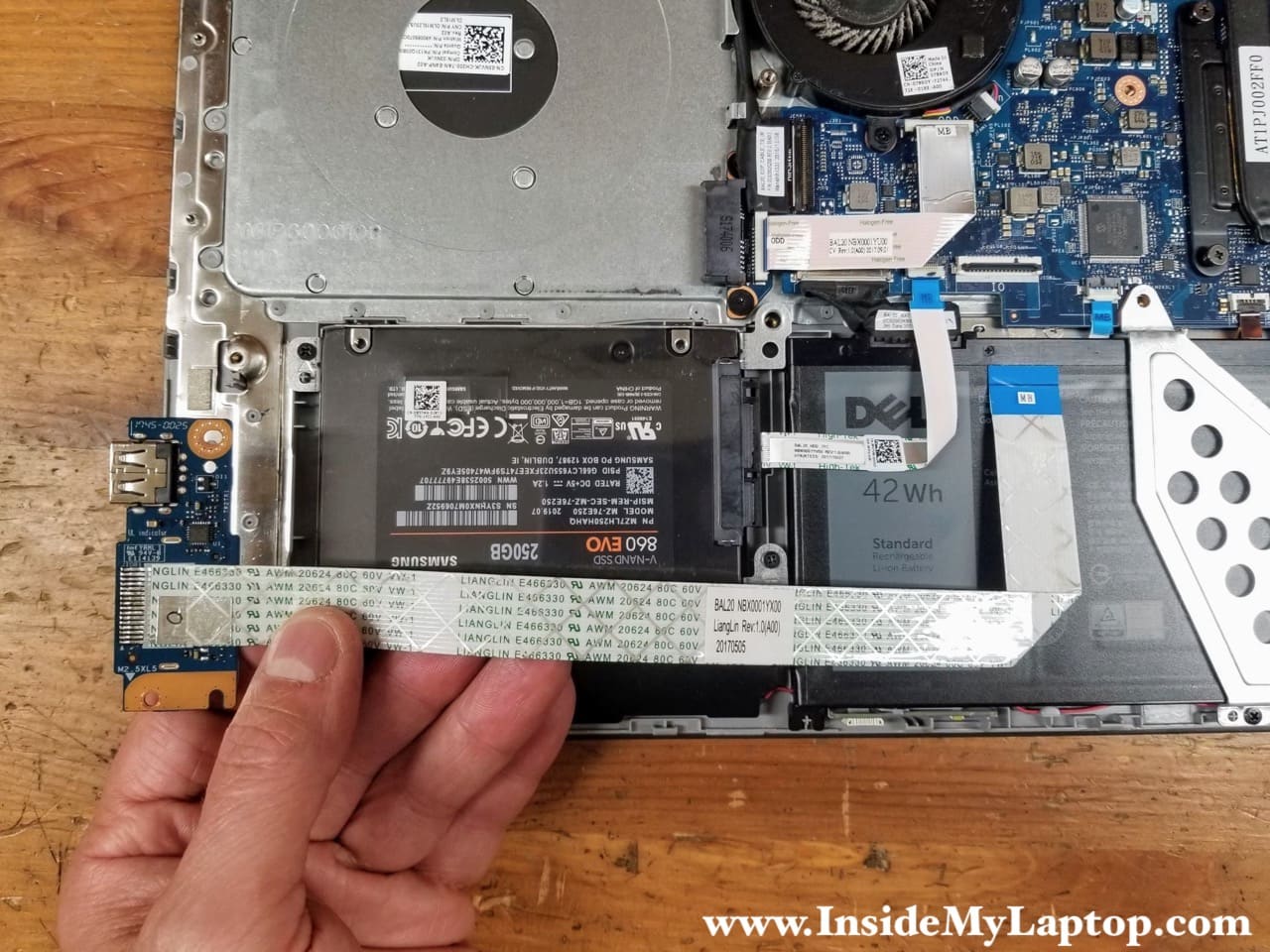
Lift up and remove the I/O board with the cable attached.
STEP 7.
Remove three screws securing the hard drive mounting bracket. Disconnect the hard drive SATA cable from the motherboard.

The hard drive cable can be released the same way as the I/O cable. Unlock the connector and pull the cable out.

STEP 8.
Lift up and remove the hard drive assembly with the SATA cable attached.
The regular spinning hard drive in this Dell Inspiron 15 5567 was replaced with a solid state drive – a very smart way to speed up any laptop.

Battery removal
STEP 9.
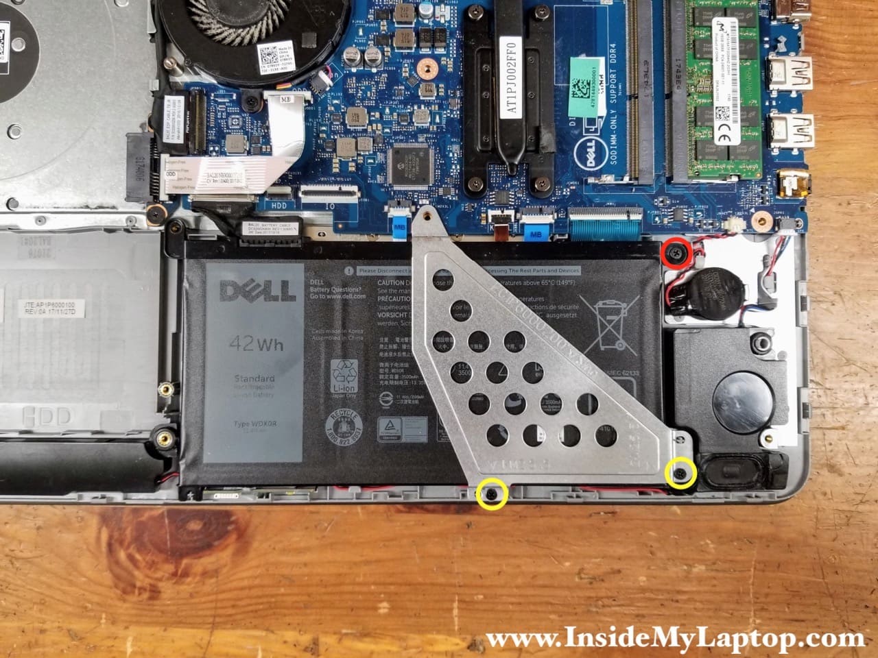
Remove one screw (red) securing the battery and two screws (yellow) securing the battery bracket. Remove the bracket.
STEP 10.
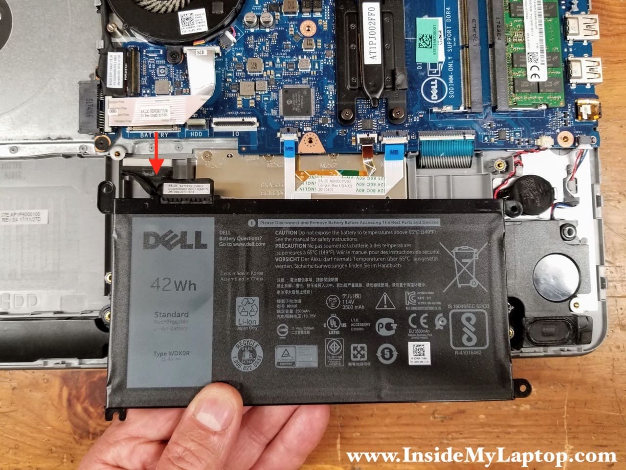
Lift up the battery and disconnect it from the motherboard.
Dell Inspiron 15 5565 5567 battery type: WDX0R. Dell part number: 0CYMGM.
Cooling fan removal
The cooling fan is permanently attached to the heatsink, so the heatsink has to be removed with the fan together.
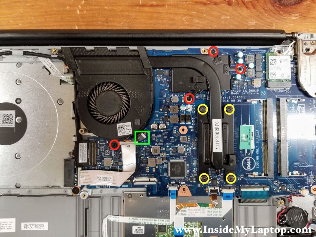
STEP 11.
Remove four screws (red) and loosen four captive screws (yellow) attaching the cooling fan/heatsink assembly to the motherboard. Disconnect the fan cable.
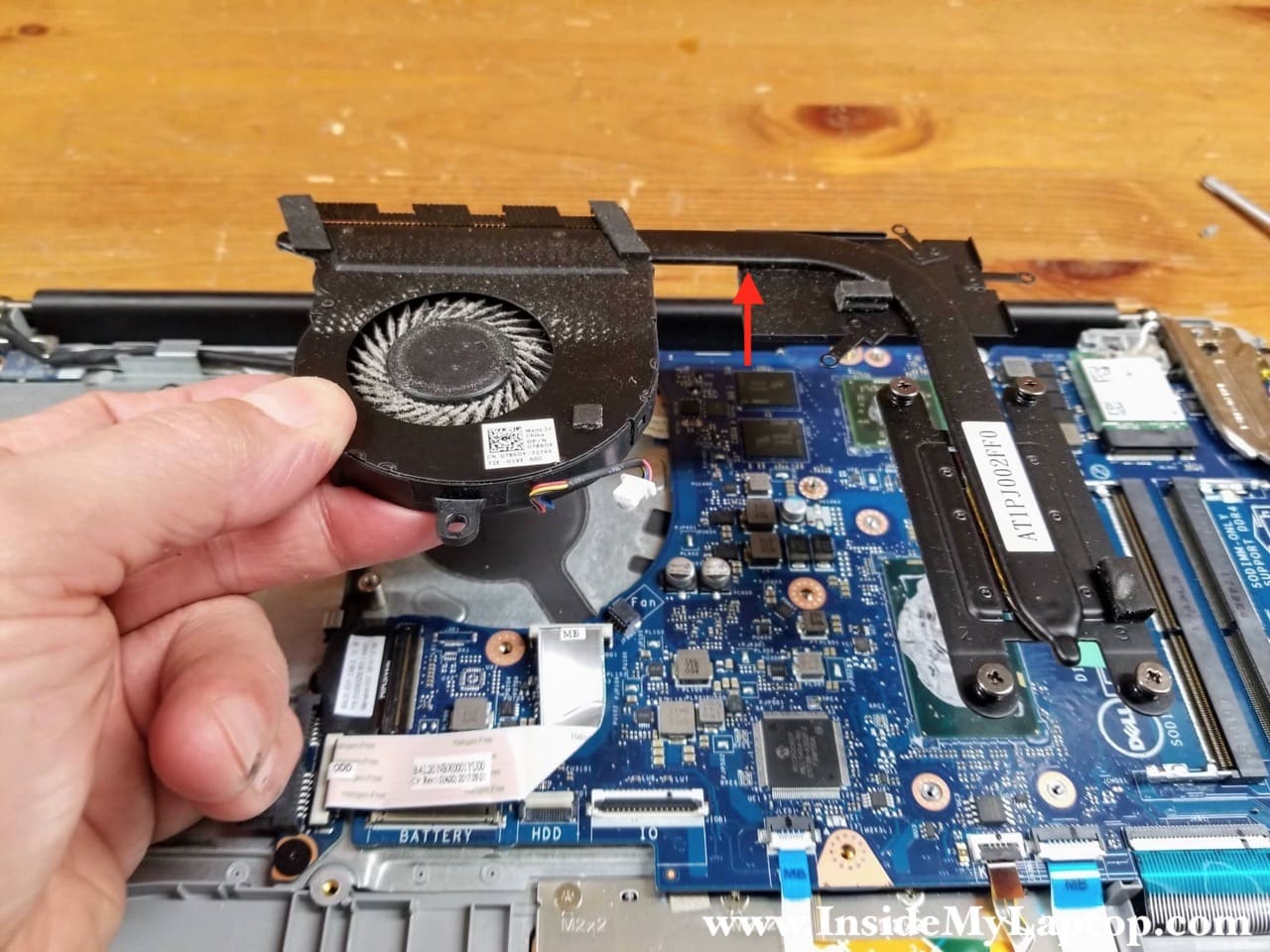
STEP 12.
While separating the fan from the top case I found that it’s glued to the power button cable. Carefully separate the fan from the cable.

STEP 13.
Remove the cooling fan/heatsink assembly.
Dell part number for the cooling assembly is: 0789DY.
Display removal
STEP 14.
Remove one screw securing the clear cover over the Wi-Fi antenna cables. Remove the clear cover.

STEP 15.
Lift up both antenna cables “heads” to un-snap them from the wireless card.
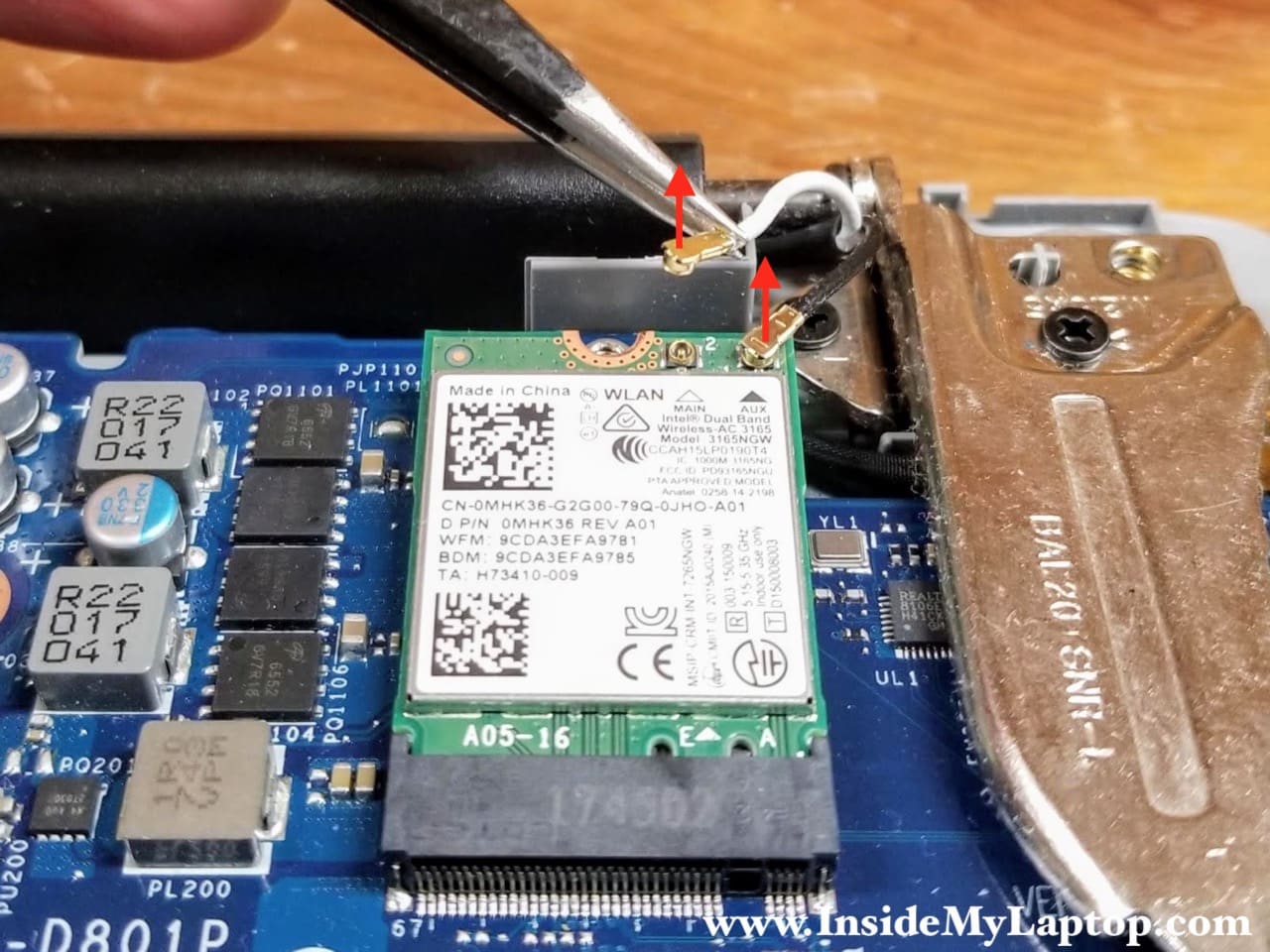
STEP 16.
Pull the wireless card out.

STEP 17.
Disconnect the display video cable from the motherboard. Un-route the display cable from the guided path on the top case.

STEP 18.
Open the display panel 90 degrees and place the laptop upside down on the edge of the desk. Remove four screws securing the left and right display hinges.

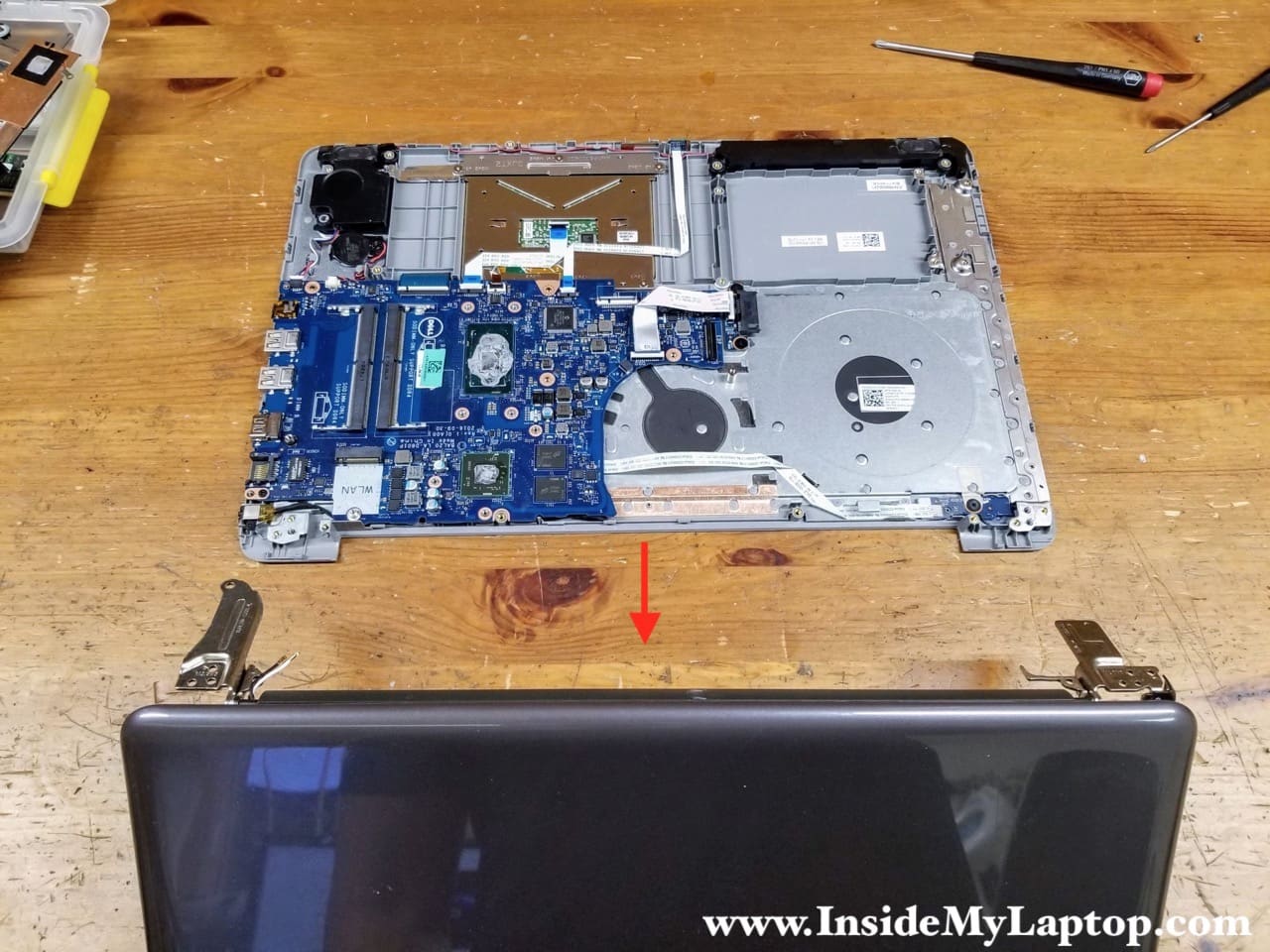
STEP 19.
Separate the display panel from the top case assembly. As I mentioned earlier, in the next article I will explained how to remove and replace the LCD screen on Dell Inspiron 15 5565 5567.
Motherboard removal
STEP 20.
Remove two screws from the optical drive connector board. Disconnect the cable from the motherboard.

Here’s how to release the optical drive connector board cable. Lift up the locking tab (red arrows) to unlock the connector and pull the cable up.

STEP 21.
Remove the optical drive connector board with the cable attached.

STEP 22.
Remove one screws securing the motherboard. Disconnect the following color-coded cables:
– Front LED light cable (orange).
– Keyboard backlight cable (yellow).
– Touchpad cable (green).
– Keyboard cable (blue).
– BIOS battery cable (red).
– Speaker cable (pink).
I will leave the BIOS battery connected to the motherboard to preserve the BIOS settings.

STEP 23.
Lift up the motherboard to separate it from the top case and turn upside down. Be careful because there are two more cables attached to the other side.

STEP 24.
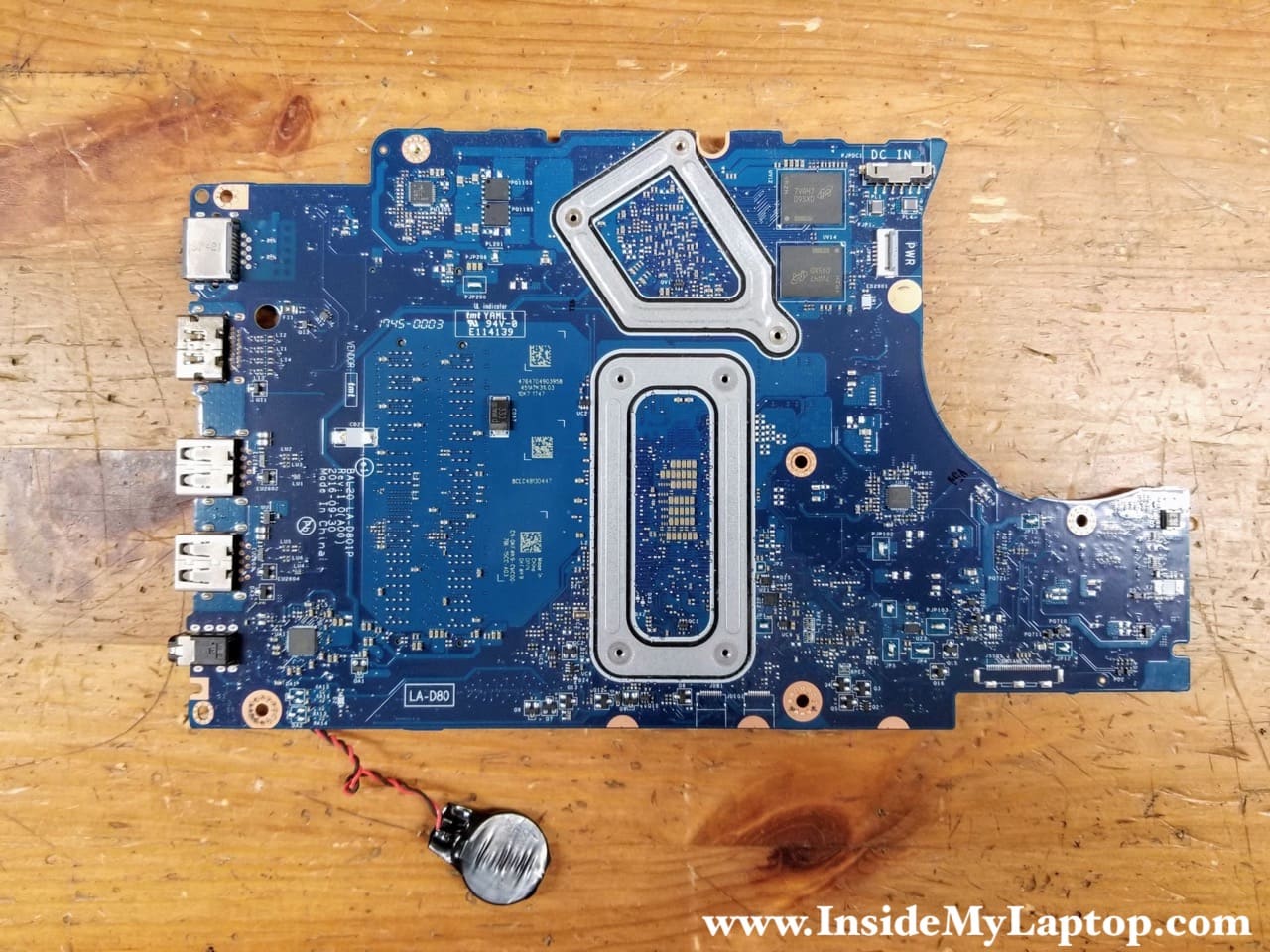
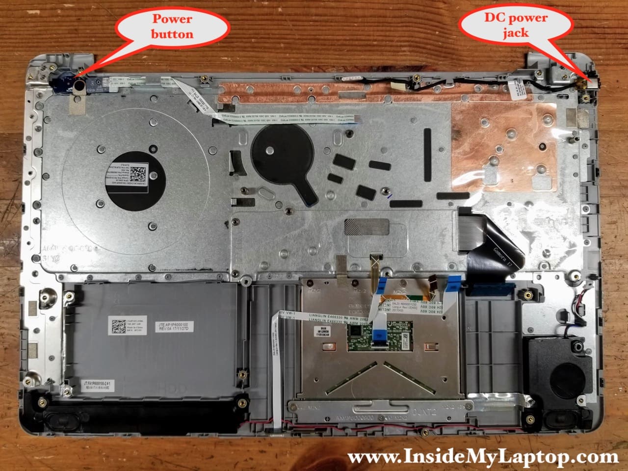
Disconnect the power button cable (orange arrow) and the DC power jack cable (red arrow).

Now you can remove the motherboard. Here’s the other side of the motherboard.
Dell Inspiron 15 5565 5567 keyboard permanently attached to the top case. It’s possible to replace the keyboard but it’s not easy. When keyboard fails, it’s easier to replace the entire top case.
The power button board, DC power jack and touchapad are removable. Yes, it’s necessary to remove the motherboard in order to replace the DC power jack.
Jim McDonald
where does the voltage come from for the screen backlite. {black screen}