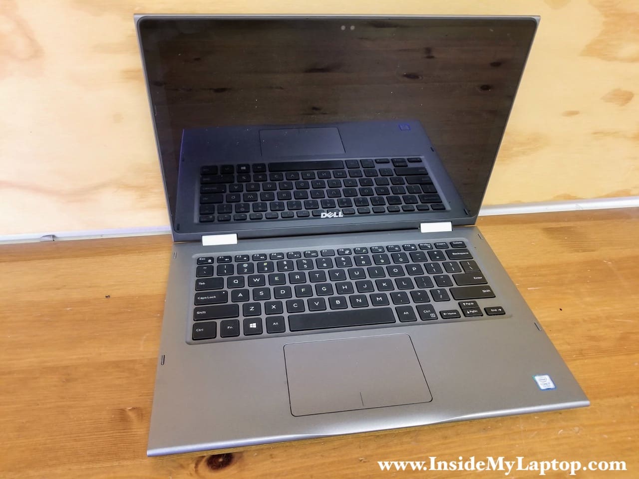
In this guide I will be taking apart Dell Inspiron 13 5000 series laptop model P69G. The disassembly guide was made for Dell Inspiron 13 5378 but also should fit Dell Inspiron 13 5368.
In the first part I will take apart the laptop base and in the second part I will show how to remove and replace the touch screen. Both parts are independent from each other and you can use either one at your convenience.
Dell Inspiron 13 5378 5368 base disassembly
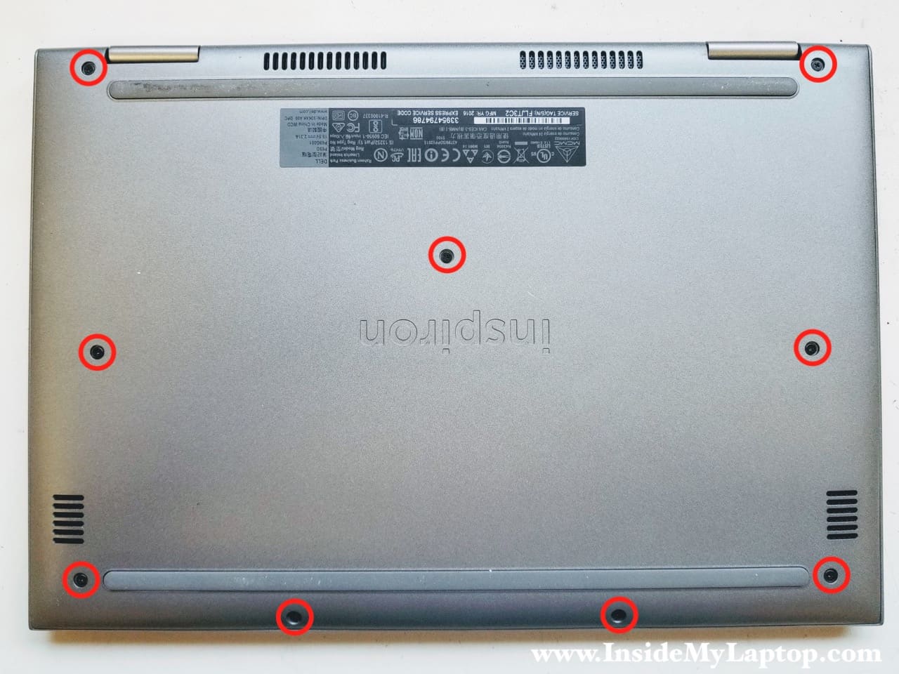
STEP 1.
Start laptop disassembly with removing all screws from the bottom cover.
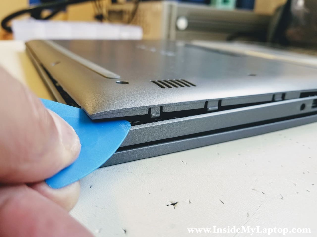
STEP 2.
Using a thin plastic case opener separate the bottom cover from the palmrest assembly.
The bottom cover has many hidden latches fastening it to the palmrest.
Move the case opener along the side and unfasten all latches.
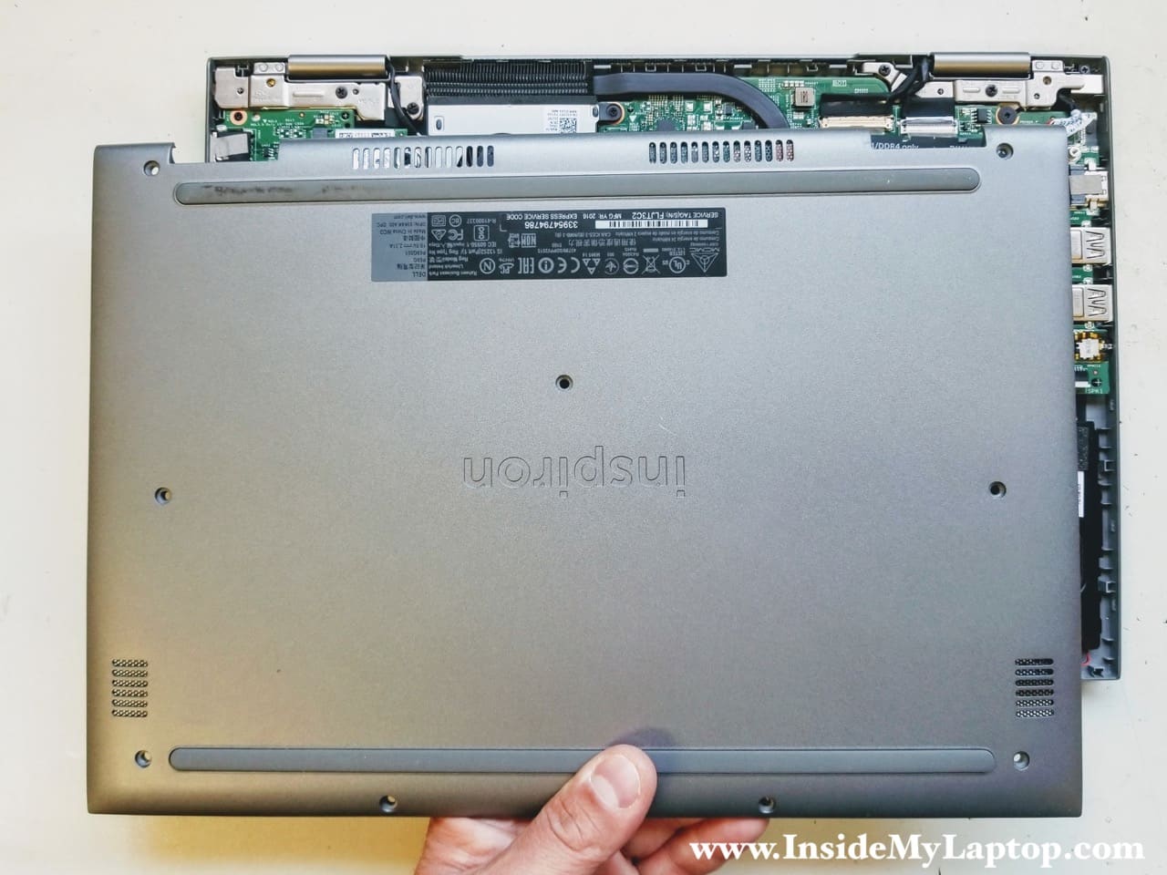
STEP 3.
Remove the bottom case cover.
STEP 4.
Remove four screws attaching the battery to the case.

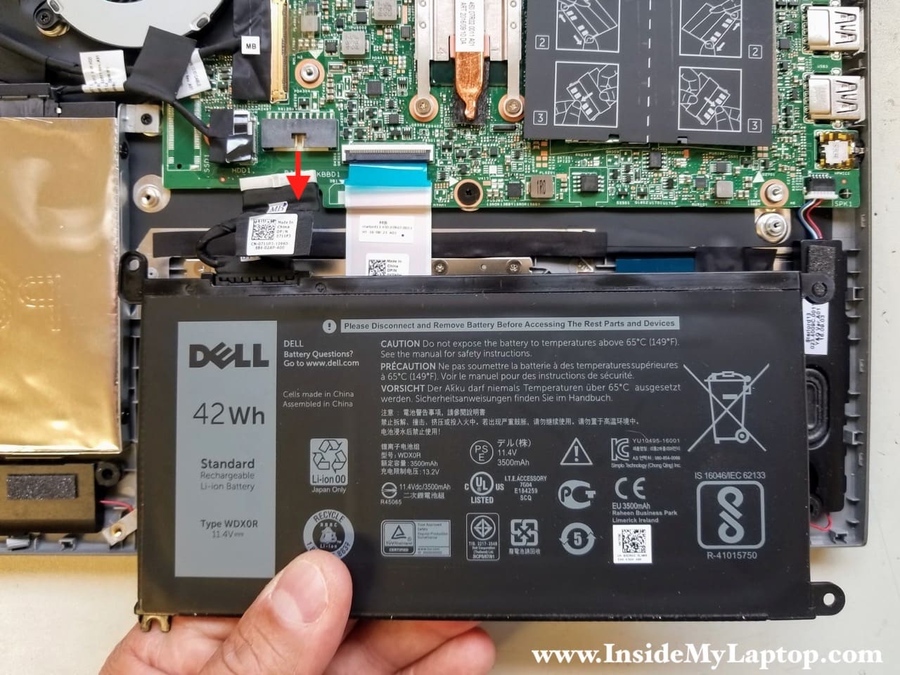
STEP 5.
Lift up the battery and remove it from the laptop. Disconnect the battery cable from the motherboard.
It is a 3500mAh battery. Battery type: 3CRH3.
STEP 6.
Remove two screws securing the hard drive caddy.
Disconnect the hard drive cable from the motherboard.
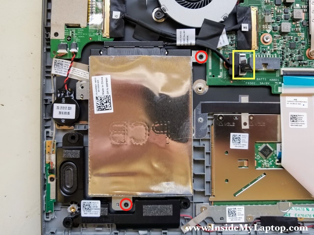
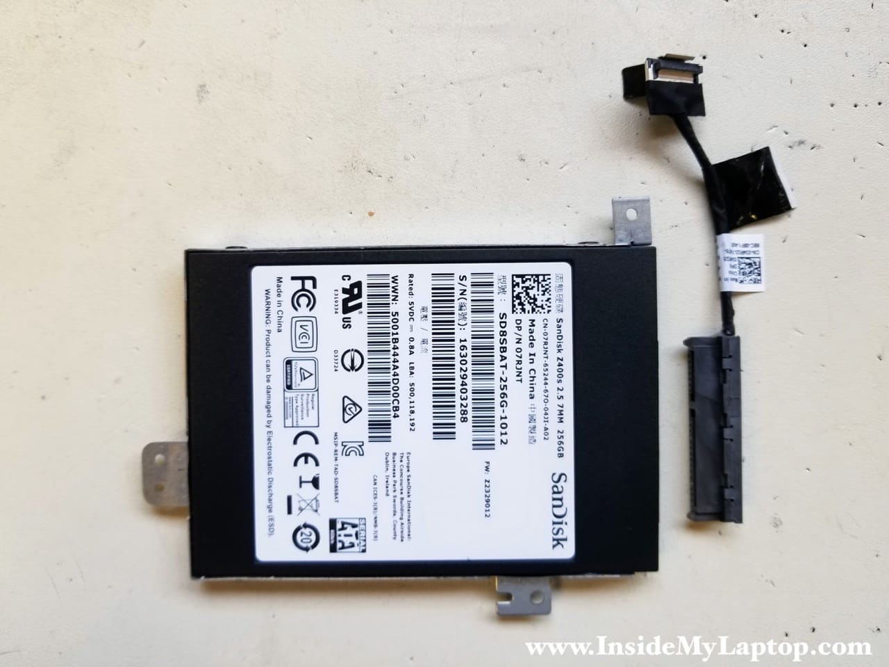
My Inspiron 13 5378 came with a 256GB SanDisk SSD. On lower end models you might have a regular hard drive installed. You can upgrade this drive to a larger capacity 2.5″ SSD.
If you are upgrading the hard drive, you will have to transfer the caddy and cable to the new one.
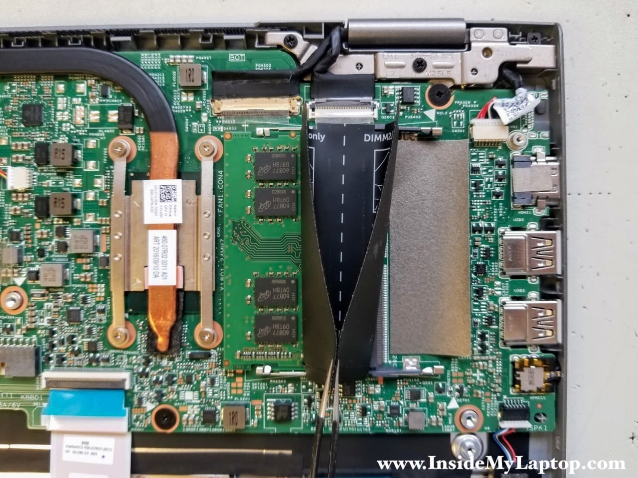
STEP 7.
The motherboard had two memory slots. In my case only one memory module was installed.
You can leave the memory module connected unless you want to replace or upgrade it.
This laptop can handle up to 16GB (2x8GB) DDR4 2400/2666/3200 SODIMM RAM modules.
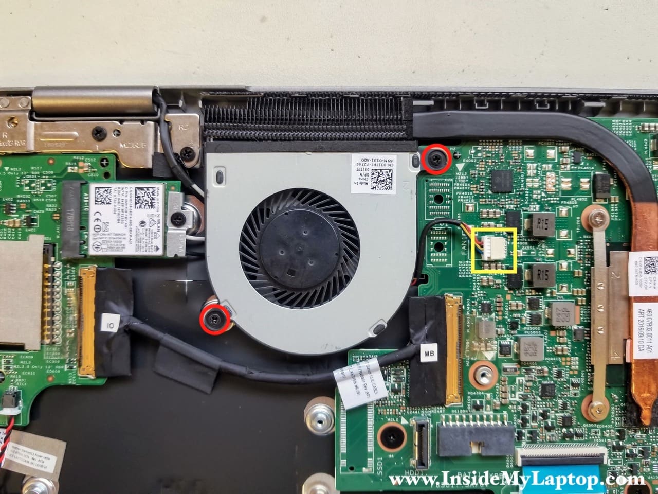
STEP 8.
Remove two screws from the cooling fan and disconnect the fan cable from the motherboard.
Remove the fan.
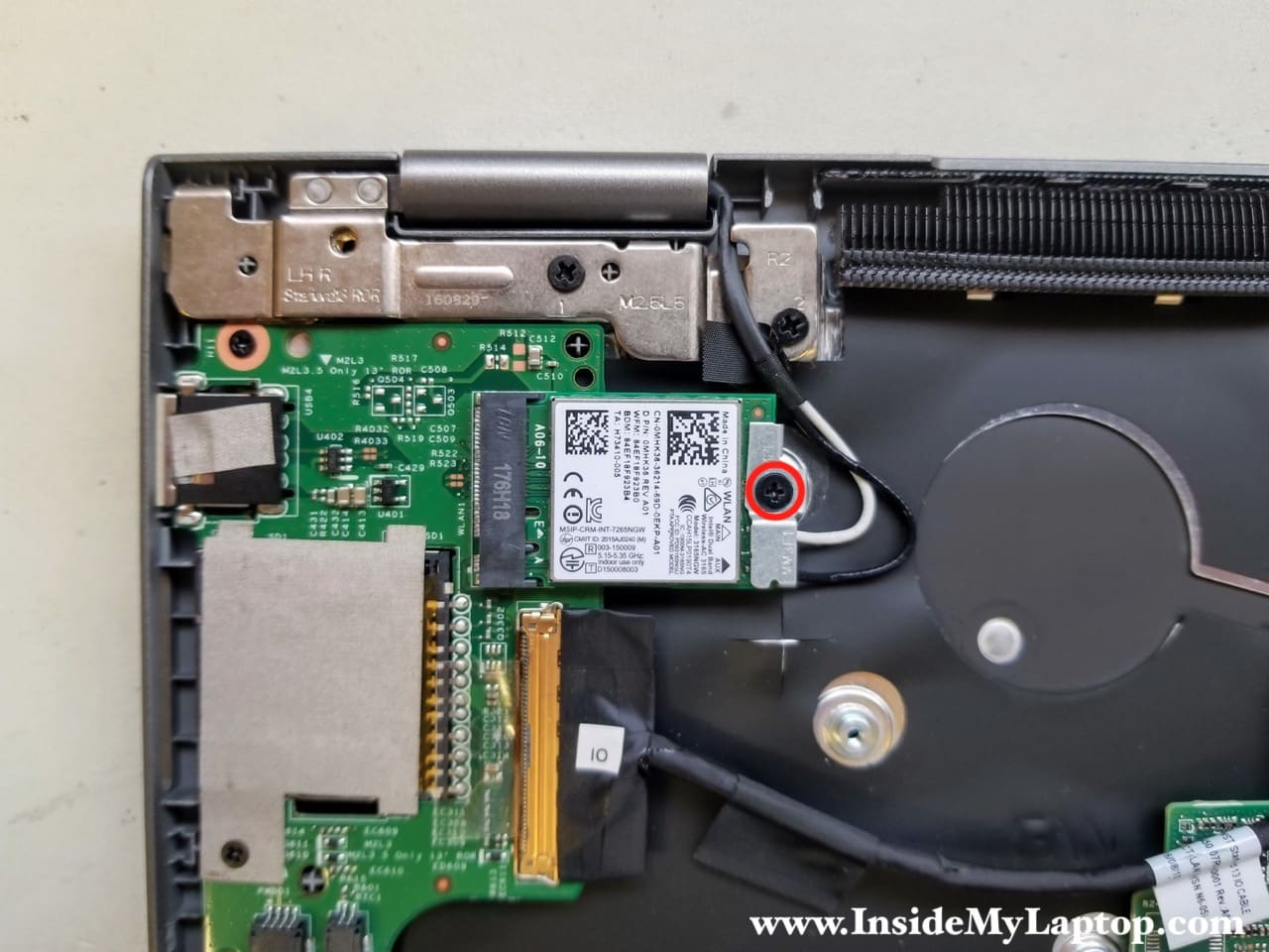
STEP 9.
Remove one screw from the metal bracket securing the WLAN module antenna cables.
Remove the bracket.
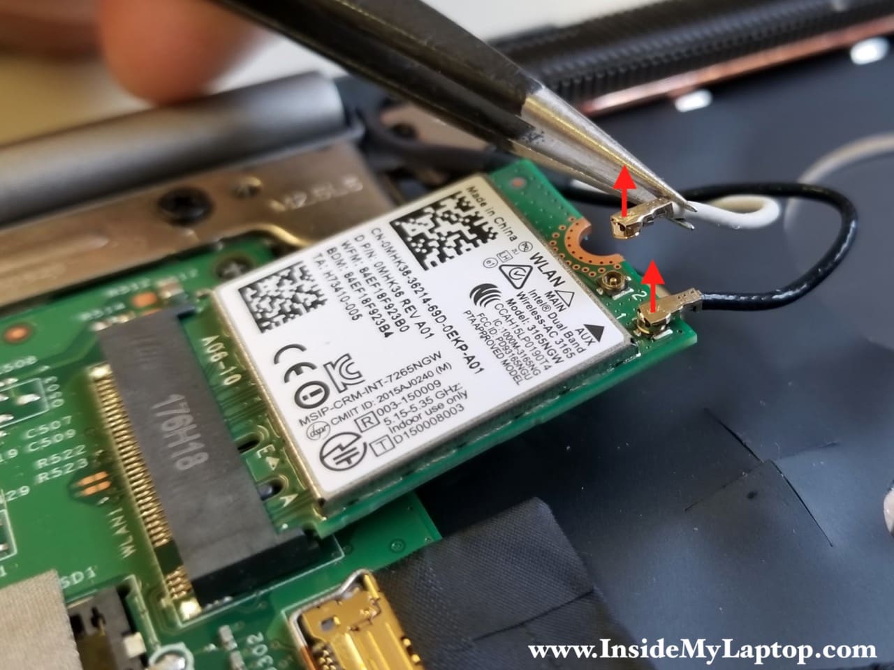
STEP 10.
Disconnect both wireless antenna cables from the WLAN card.
Pull the WLAN card out of the slot.
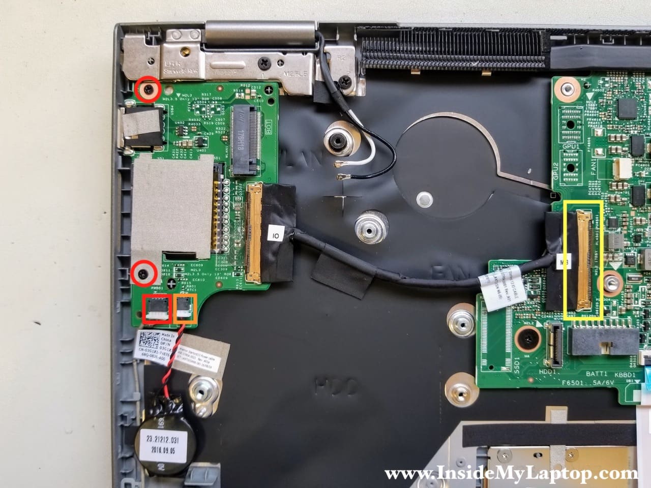
STEP 11.
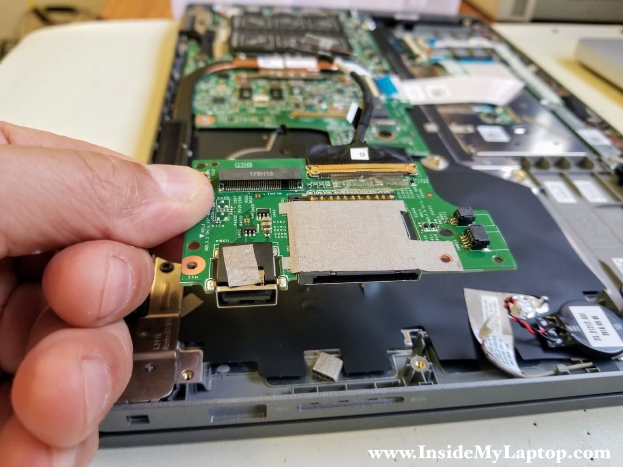
Remove two screws securing the USB SD card reader board.
Disconnect the power button board cable (red square) and CMOS battery cable (orange rectangle).
Disconnect the USB SD card board cable from the motherboard (yellow rectangle).
STEP 12.
Remove the USB SD card reader board with the cable.
STEP 13.
Disconnect the following cables from the motherboard:
- Keyboard cable (red rectangle)
- Speaker cable (blue square)
- Display video cable (orange rectangle)
- Touch-screen cable (yellow rectangle)
- DC-IN power jack cable (green square)
Remove three screw securing the motherboard to the top case assembly.

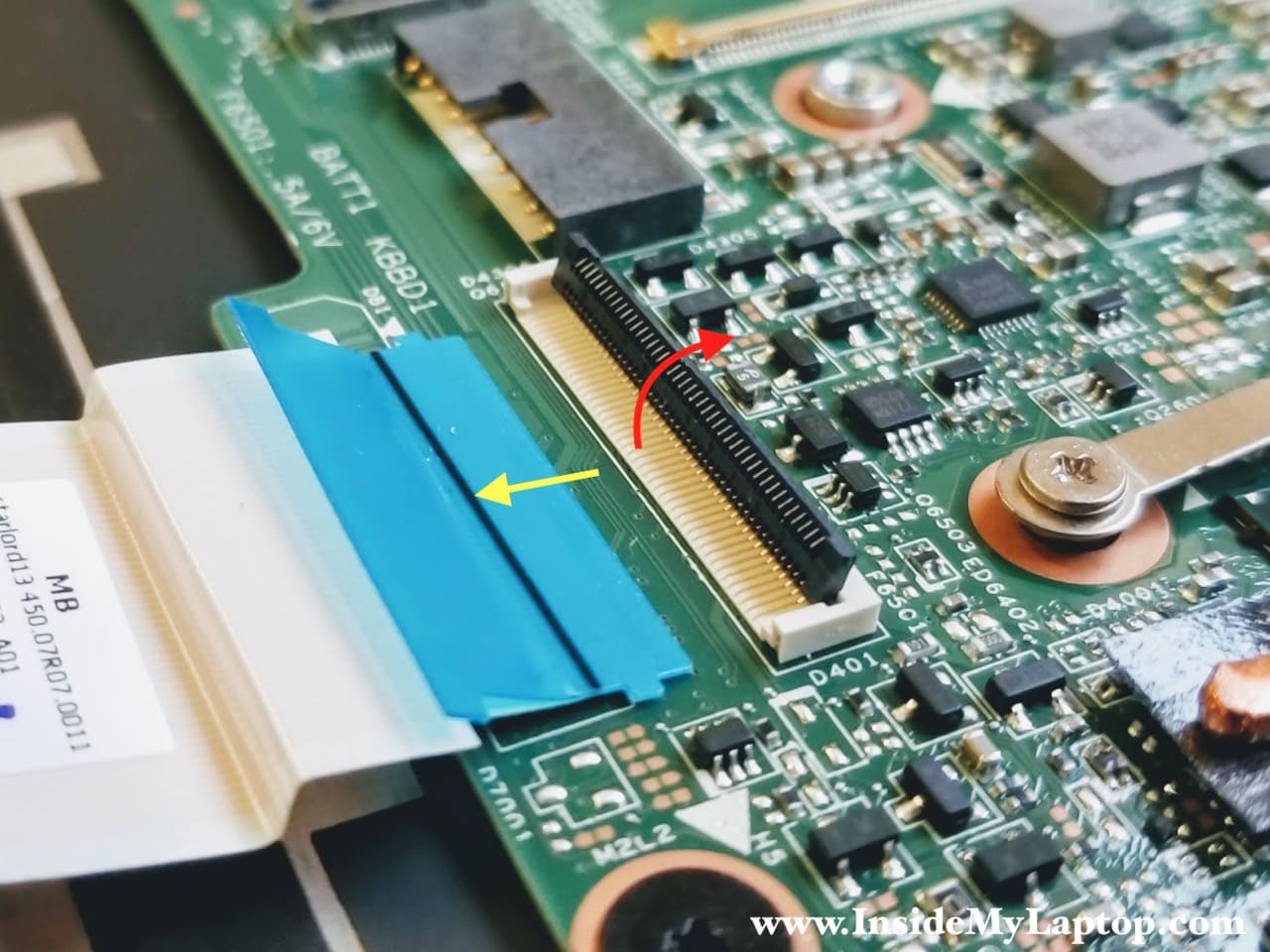
Here’s how to disconnect the keyboard cable and other flat cables:
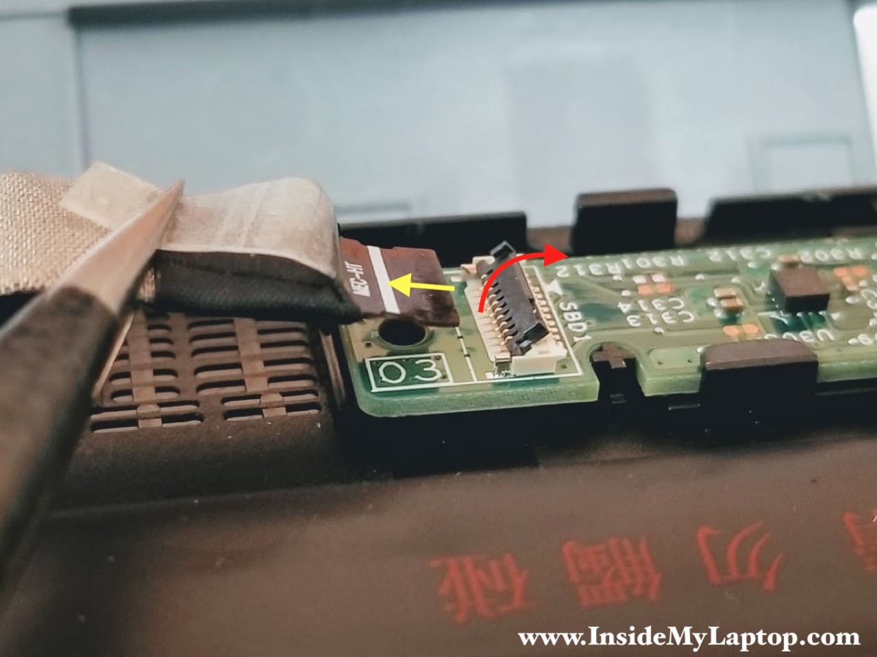
- Lift up the locking tab to unlock the cable (red arrow)
- Pull the cable out of the connector (yellow arrow)
STEP 14.
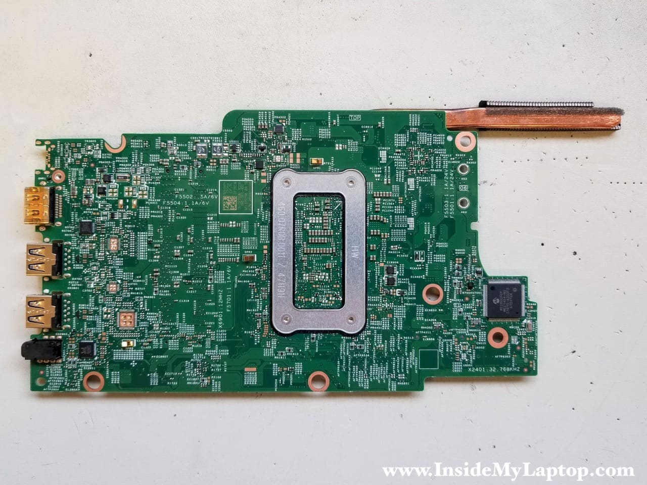
Remove the motherboard from the base.

Here’s the other side of the motherboard.
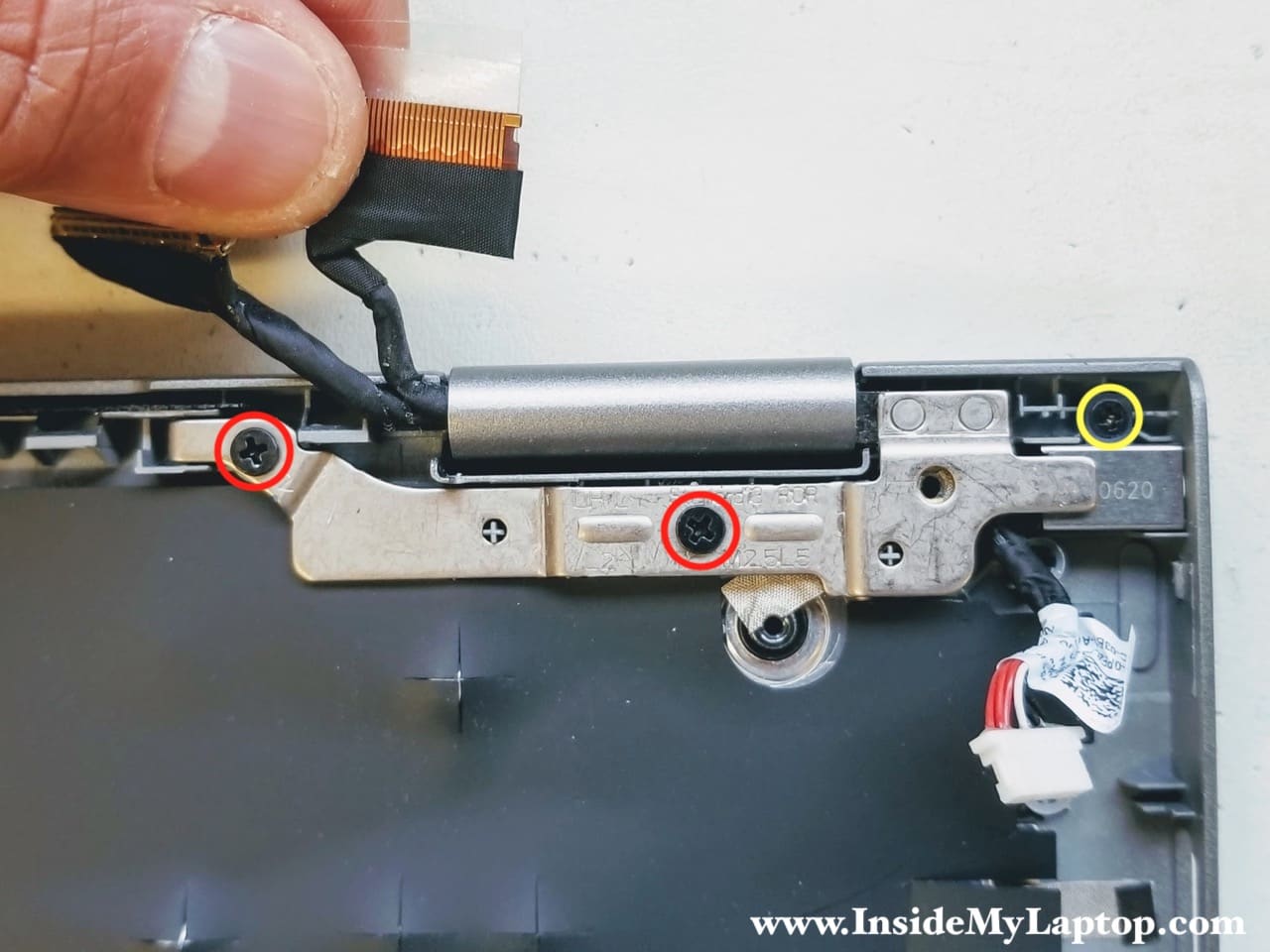
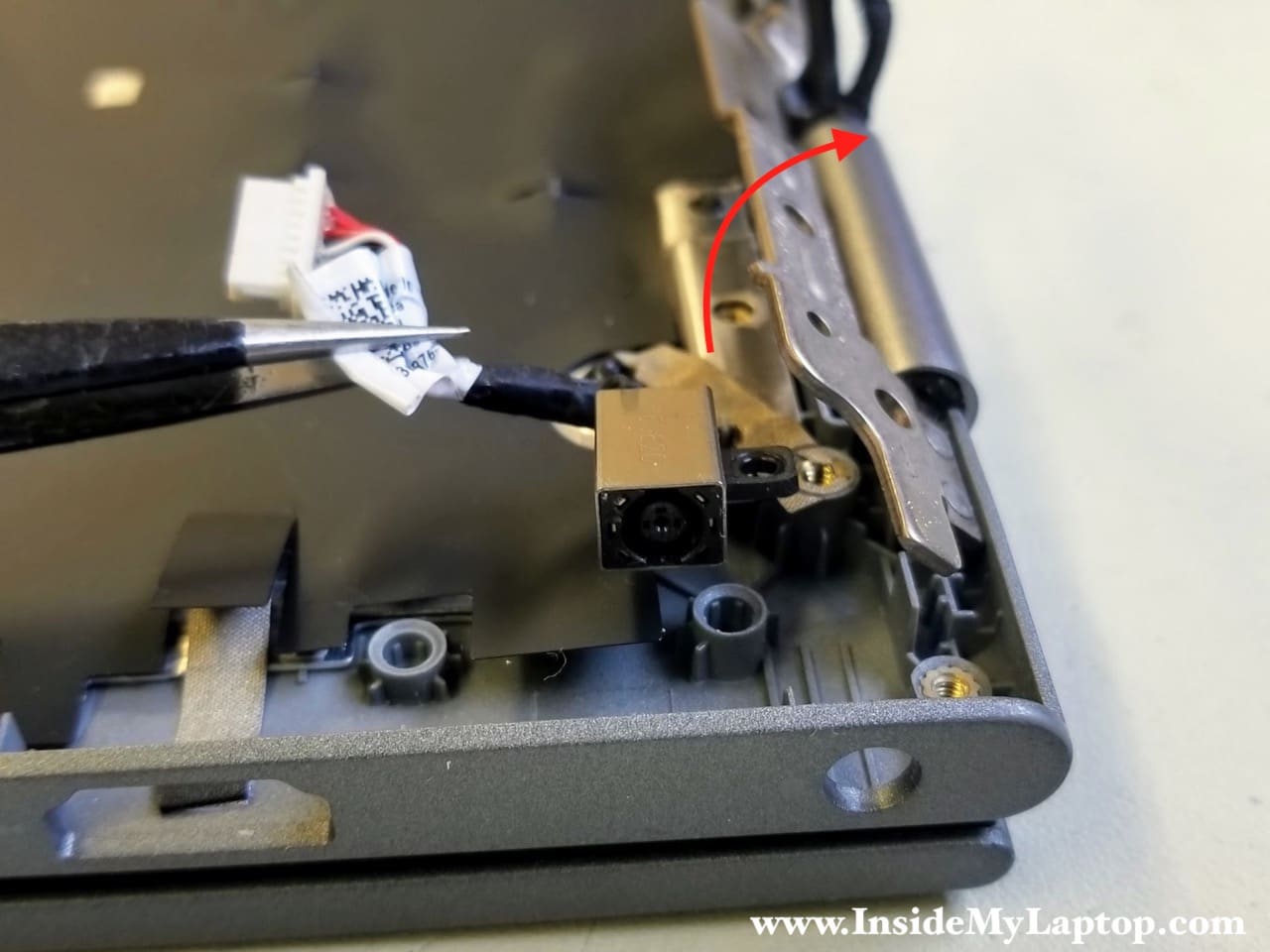
STEP 15.
The DC-IN power jack is mounted under the hinge.
Remove two screws attaching the hinge to the base. Remove one more screw securing the DC-IN power jack.
STEP 16.
Lift up the hinge so it opens up at a 30 degree angle.
Now you can remove the DC jack.
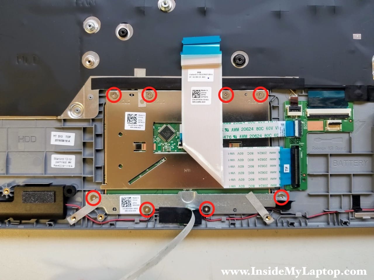
STEP 17.
The touchpad is secured to the palmrest with 8 screws. I’m not going to remove it but it should be pretty much straight forward.
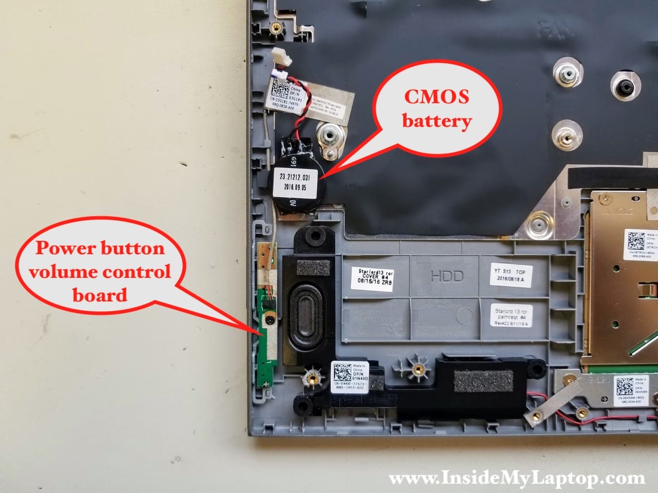
STEP 18.
The CMOS battery attached to the case with adhesive tape.
The power button and volume control board is secured by one screw.
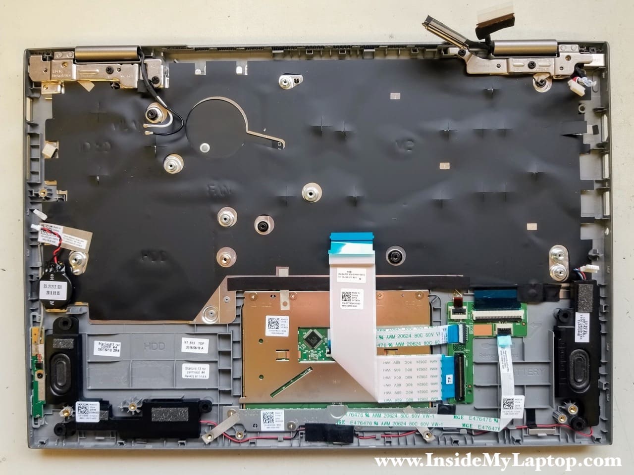
The keyboard is permanently riveted to the top case and cannot be easily removed.
If your keyboard failed, it will be necessary to replace the entire top case/palmrest assembly. Check out this keyboard replacement trick.
Dell Inspiron 13 5378 5368 touchscreen replacement
The touchscreen can be removed and replaced without going through all disassembly steps show in the first part.
Before opening up the display panel, I would strongly recommend disconnecting the battery as shown at the beginning of this guide.
STEP 1.
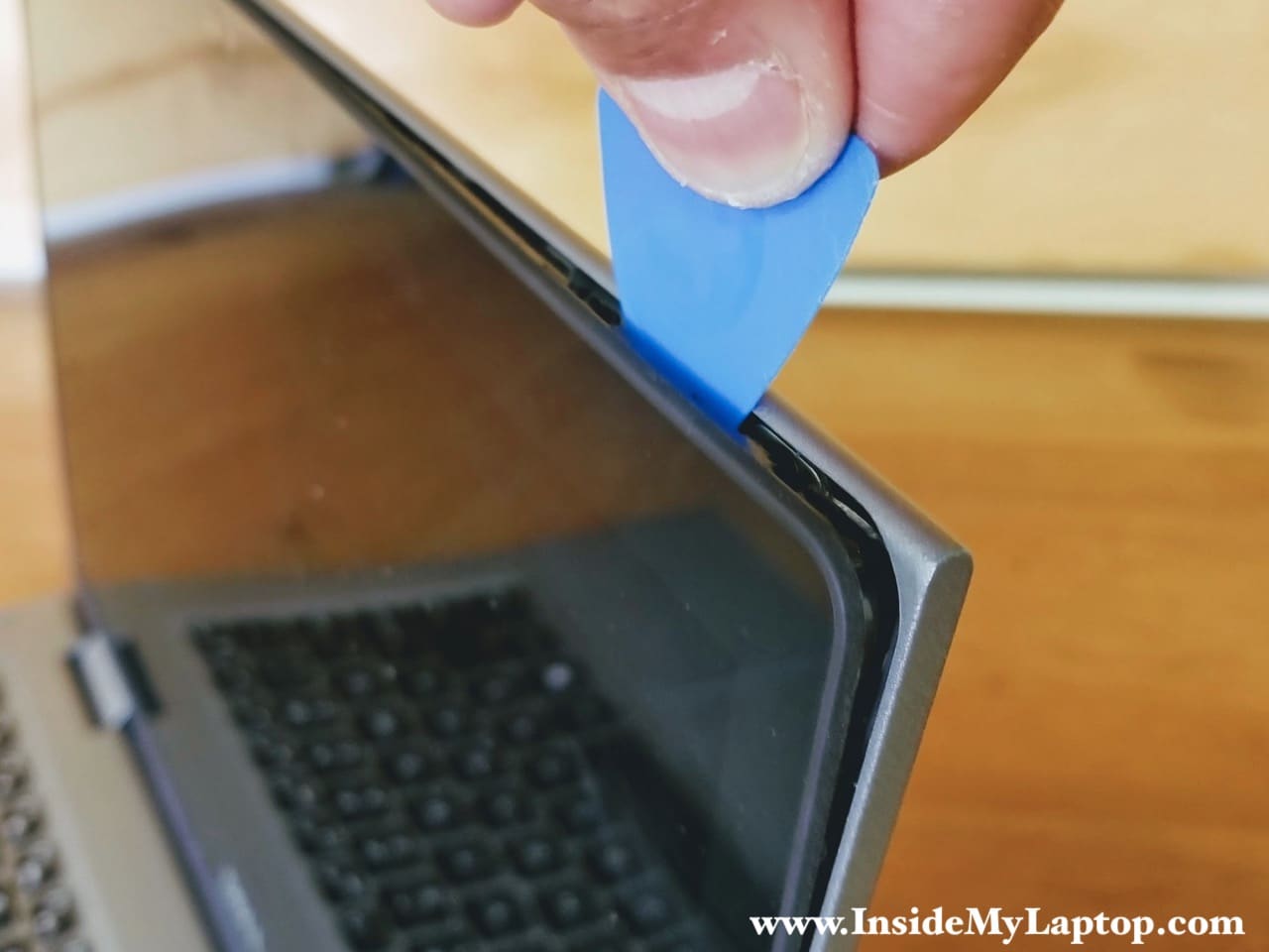
Using a thin case opening tool start separating the touchscreen from the display back cover.
Move the tool along the side and unfasten hidden latches.
STEP 2.
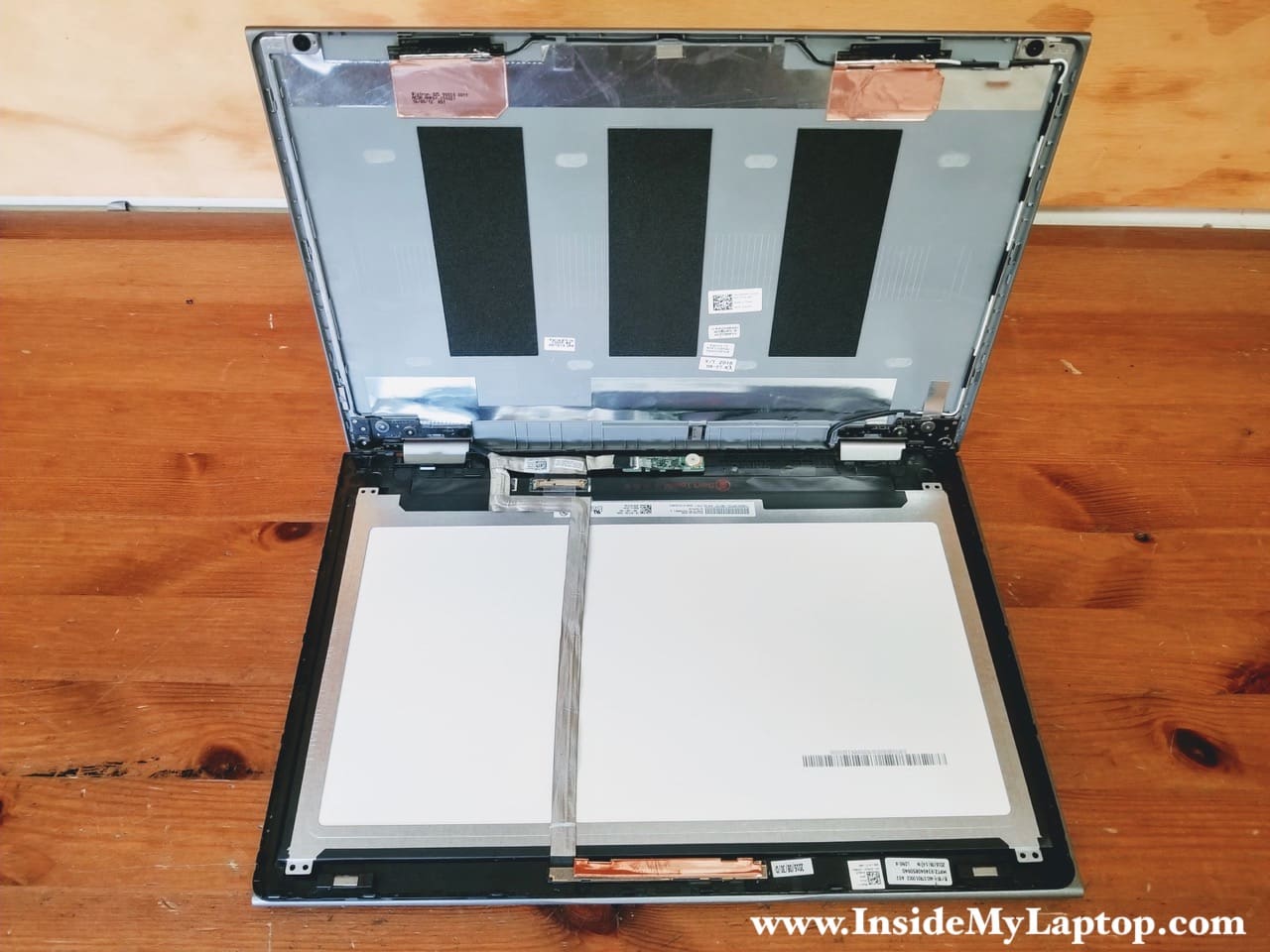
When all latches are unlocked, you can separate the touchscreen assembly from the back cover.

STEP 3.
Place the touchscreen the front side down on the keyboard.
Now you can access the display cable on the back.
STEP 4.
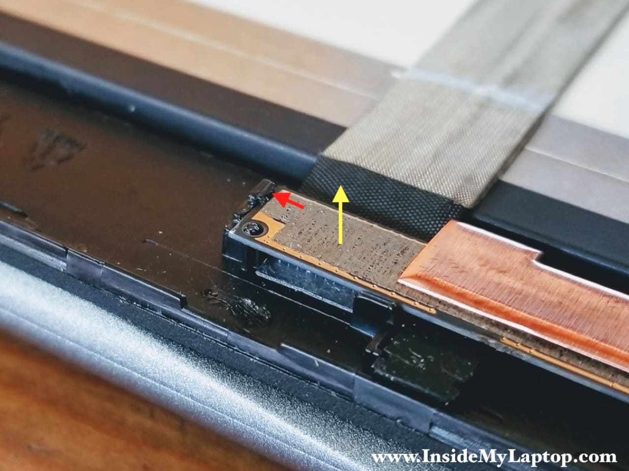
The webcam module is glued to the bezel with adhesive tape and secured by latch on the side.
Push on the latch (red arrow) and at the same time lift up the webcam module (yellow arrow).
STEP 5.
Continue separating the webcam module from the bezel.
STEP 6.
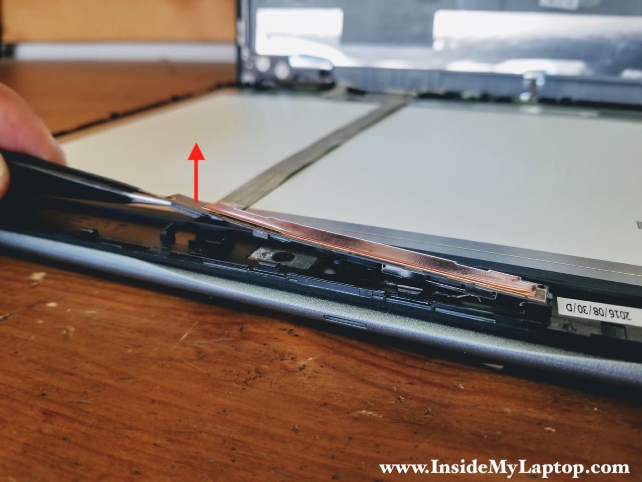
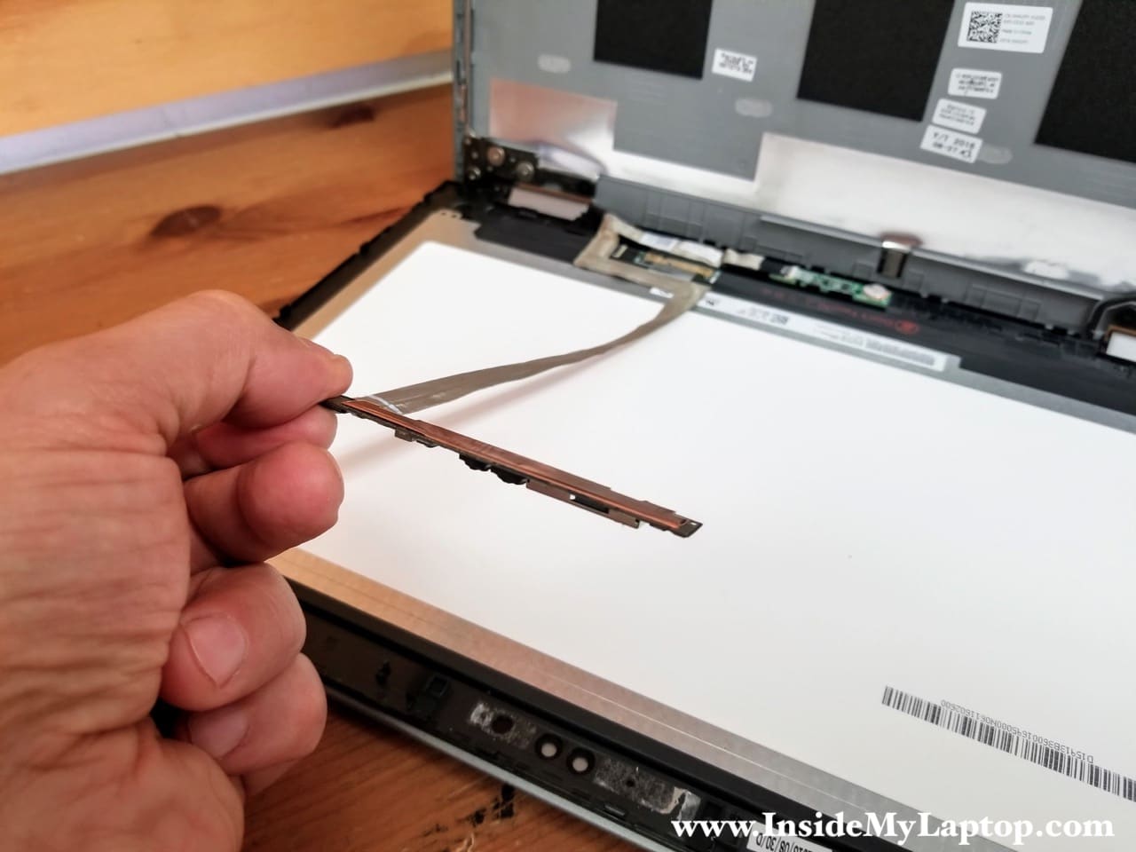
Peel off the webcam cable (part of the display cable) from the back side of the screen.
The cable is secured by adhesive tape.
STEP 7.
Disconnect the cable from the sensor board.
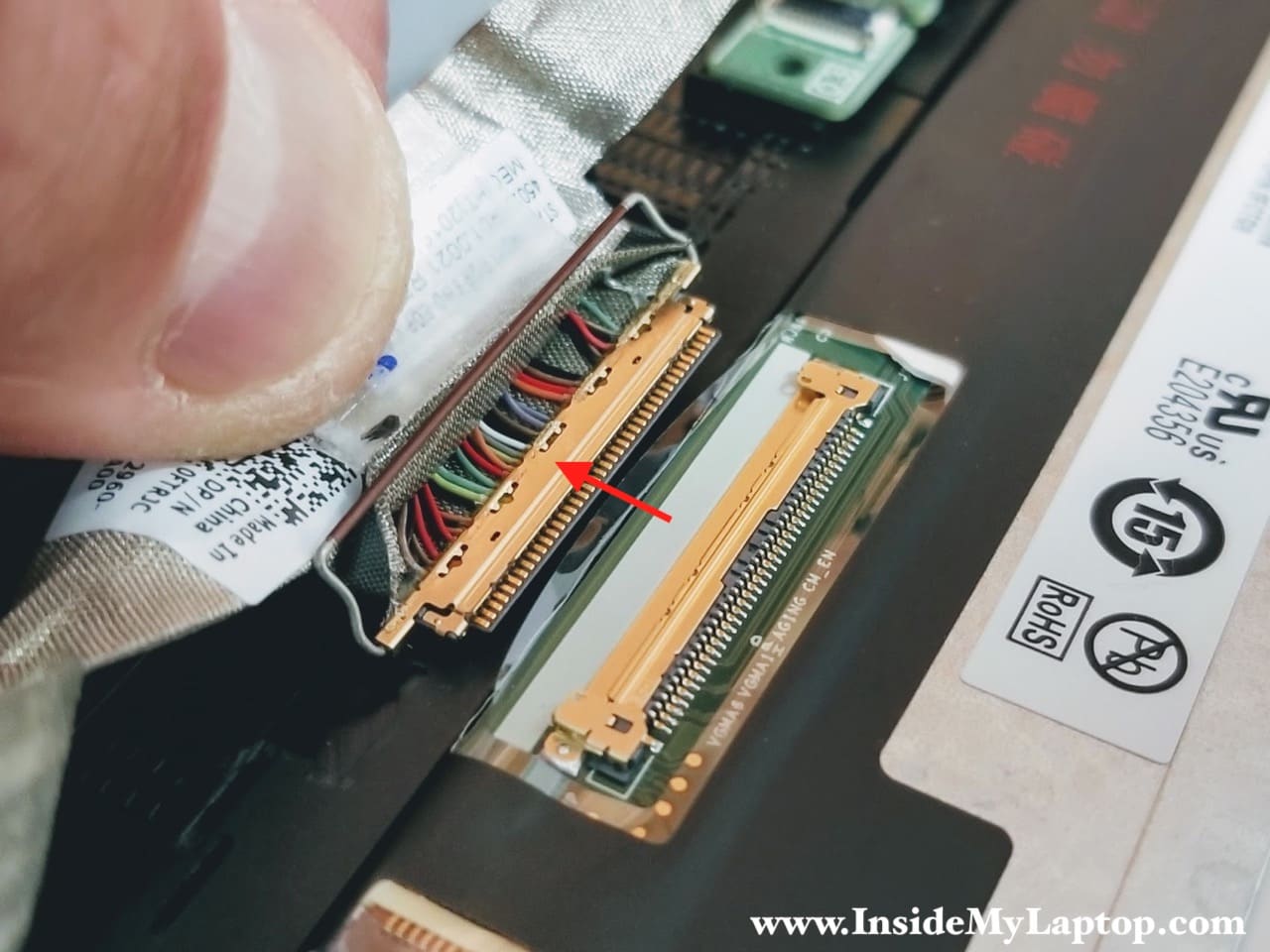
STEP 8.
Disconnect the video cable from the screen.
STEP 9.
Now you can remove the touchscreen assembly (LCD screen with digitizer) from the laptop and replace it if necessary.
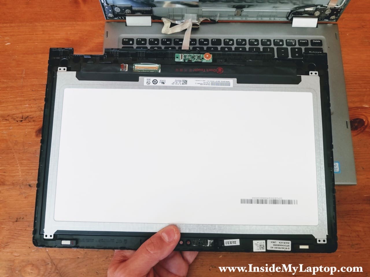
You can find a replacement touchscreen using Dell part number from the original one.
In my Dell Inspiron 13 5378 I had the touchscreen assembly with the following part number: 1H0JY.

mario
how to replace memory battery in dell N7010?
IML Tech
@ mario,
Are you asking about the CMOS battery?
Check out my guide for Dell Inspiron 17R N7110 here: https://www.insidemylaptop.com/disassemble-dell-inspiron-17r-n7110/
It should be pretty close to n7010 model. Maybe different screw locations but overall very similar.
The CMOS battery located under the top case. It’s shown in the step 17.
Harman
How to replace the keyboard only ??
IML Tech
@ Harman,
It’s possible to replace just the keyboard but it’s not easy.
The keyboard is permanently attached to the top case.
How to replace it. I haven’t done it myself but here’s how I see the process.
1. Remove the top case as it shown in the step 18.
2. Remove the black mylar cover.
3. Separate the metal plate securing the keyboard. You will have to break about 30 plastic rivets attaching the metal plate to the top case.
4. Replace the keyboard with a new one. You can find a new keyboard on eBay for about $30-40.
5. Reattach the metal plate. Probably you can reuse old rivets and secure them using a soldering iron (to melt plastic).
George
What I can use to stick the black milar cover back on?
Jack Wu
good job, good service
G HILL
good job
I need to replace replace some keys
I would be grateful for any assistantance
IML Tech
G HILL, what is the reason for replacing the keys? Did you spill a liquid or some keys just stopped working? If that’s the case, you cannot just replace the keys. It’s necessary to replace the entire keyboard which is a part of the top case assembly.
Thai Hoa Pham
My Touch-screen cable (yellow rectangle on the image) was broken.
Does it impact to signal form mic, camera as well?
Thank you!!
Simone
Any way to fix the charging circuit? I’ve replaced the battery and adapter but the battery is still not charging. From what I read that leads to the charging circuit. I don’t want to replace the motherboard if I don’t have to.
thanks!
Tom C
Nice post and very useful!
I replaced my dead motherboard with a new one kept getting the “ac adapter not recognised – pc will run in low power and not charge” message. I have two ac adapters and two batteries and two internal dc jacks, and i get that message for them all. I assumed that meant my new motherboard was dead too, so I returned it and got a third one…same problem! Any ideas?
Gil
My Inspiron 13 5378 2-in-1 no longer charge the battery so I replaced the battery but still battery was not charging. Bought a new charger but still no luck. The battery eventually drained but somehow the laptop shut down even with ac charger plugged in. I recalled I spilled coffee on my laptop and so I am thinking there must be some short circuit somewhere or some power supply fuse busted. Where are the power supply fuse located and how to access it? I noticed the insulation underneath the keyboard isolating it from the mother board. Is there some pcb there that might be shorted? How to access it?