In this disassembly guide I show how to take apart Dell XPS 15 9530 or Precision m3800 laptop. Regulatory model: P31F.
While Dell XPS 15 9530 targets mostly home users and Precision m3800 is more business oriented, both models are very similar. This guide will help you to access and remove all main internal components.
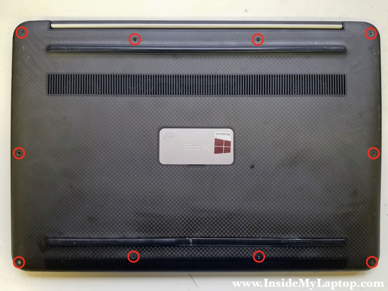
STEP 1.
Remove ten T5 Torx screws securing the bottom case.
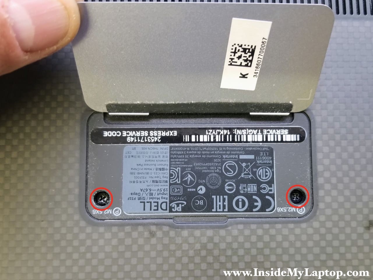
STEP 2.
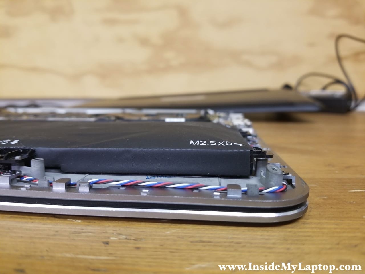
Remove two more screws located under the magnetic door.
STEP 3.
Separate the bottom case from the rest of the laptop and remove it.
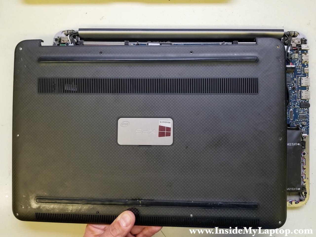
In my Dell XPS 15 9530 the battery is swollen and must be replaced.
STEP 4.
Remove seven screws attaching the battery to the top case.
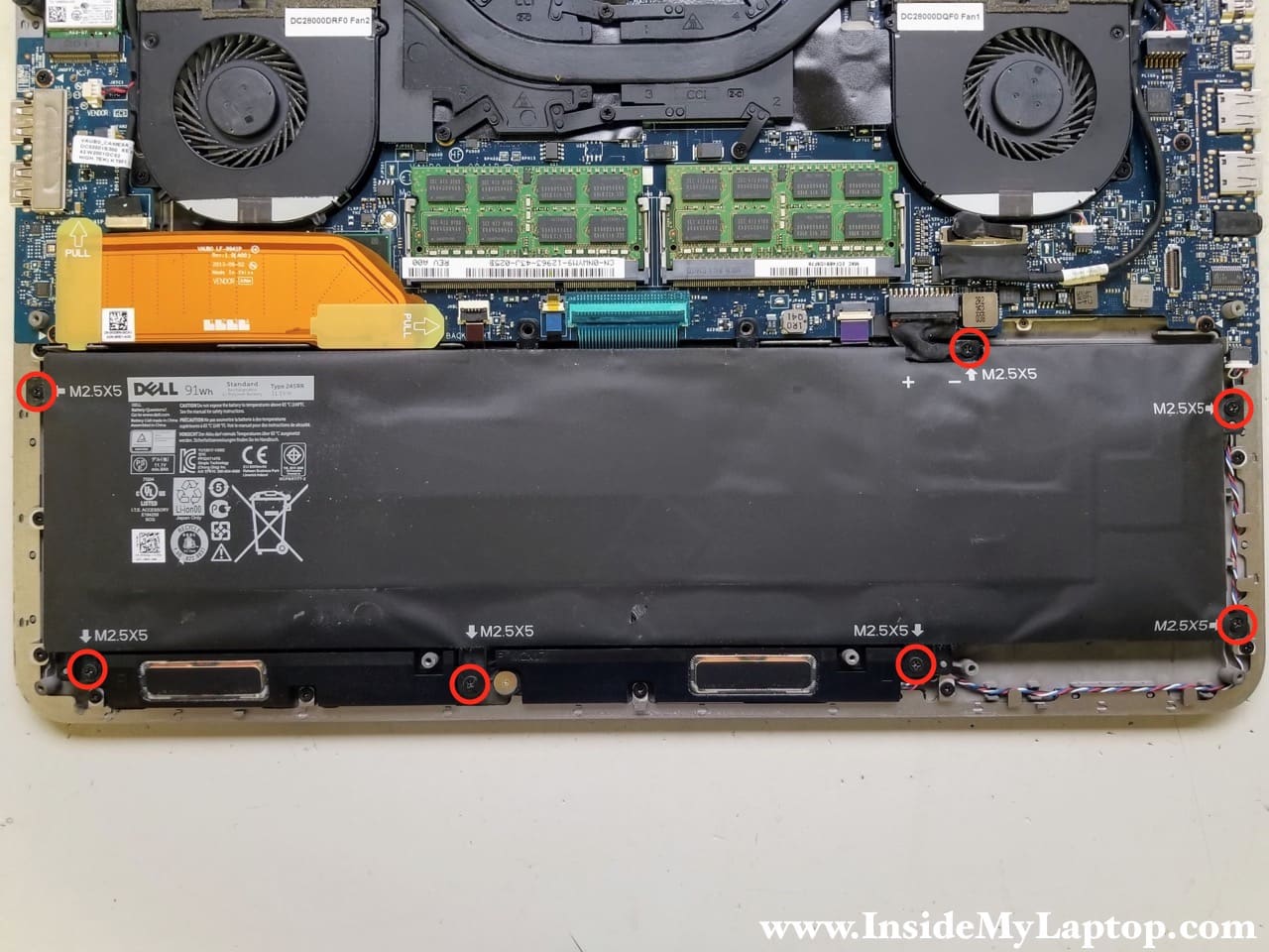
STEP 5.
Lift up the battery, unplug the battery cable from the motherboard and remove it from the laptop.
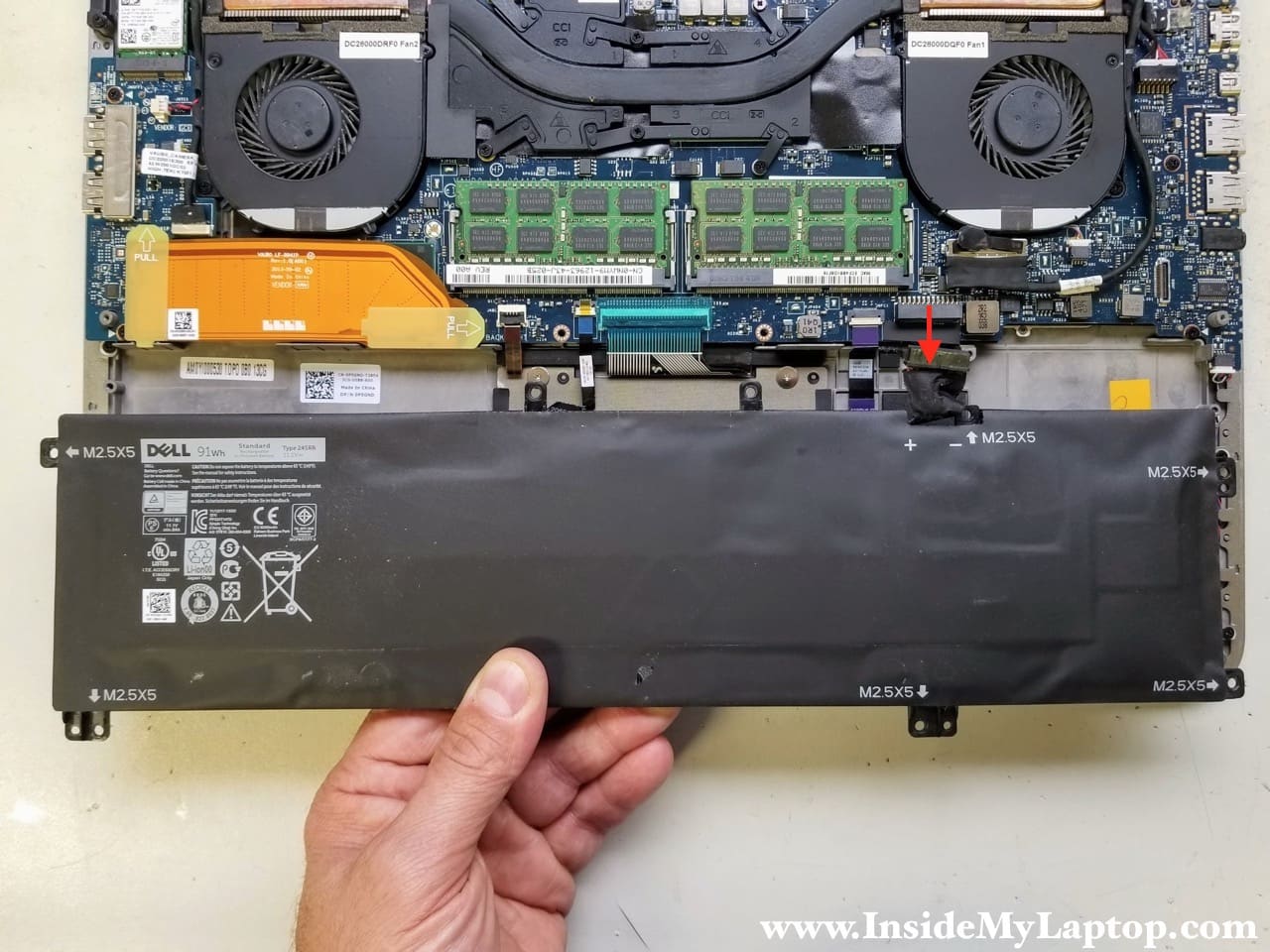
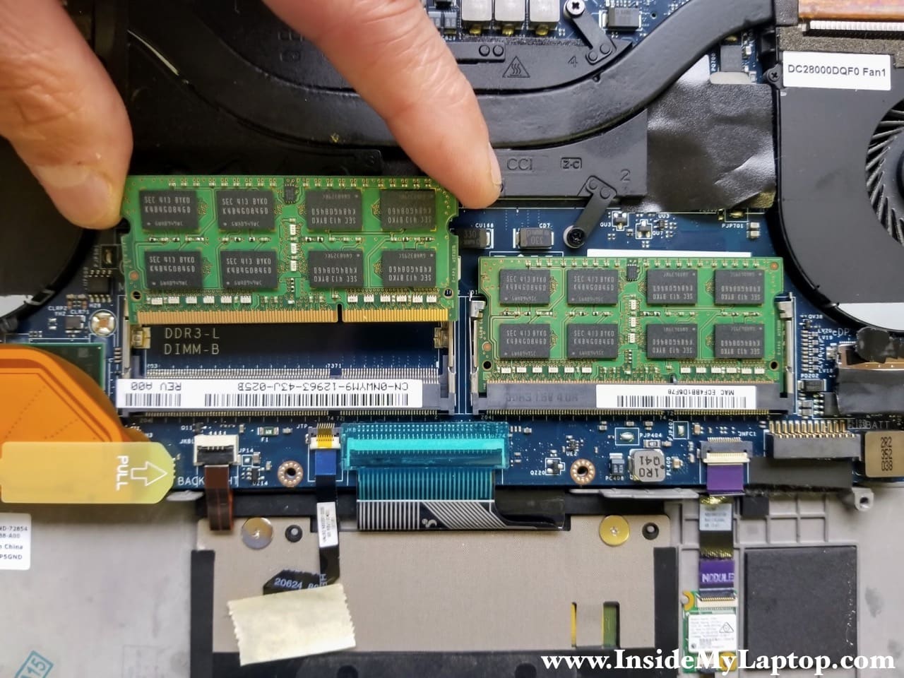
STEP 6.
The motherboard has two memory slots. Remove both memory modules if necessary. This step is optional and you can leave RAM modules connected.
This laptop can handle up to 16GB (2x8GB) DDR3-12800 SODIMM RAM modules.
STEP 7.
Remove six screws attaching the heatsink to the motherboard.
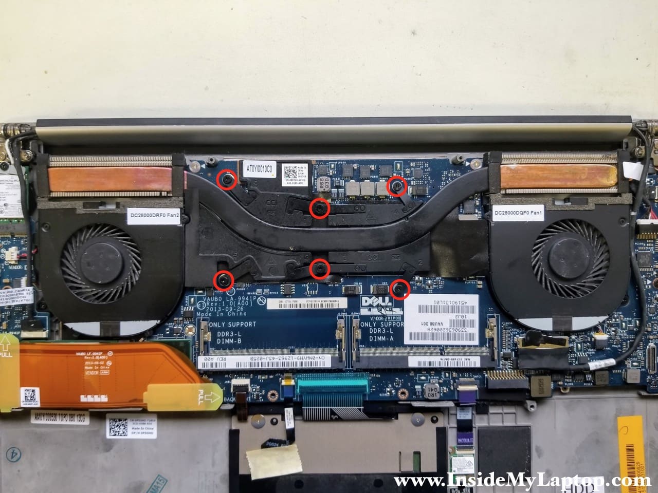
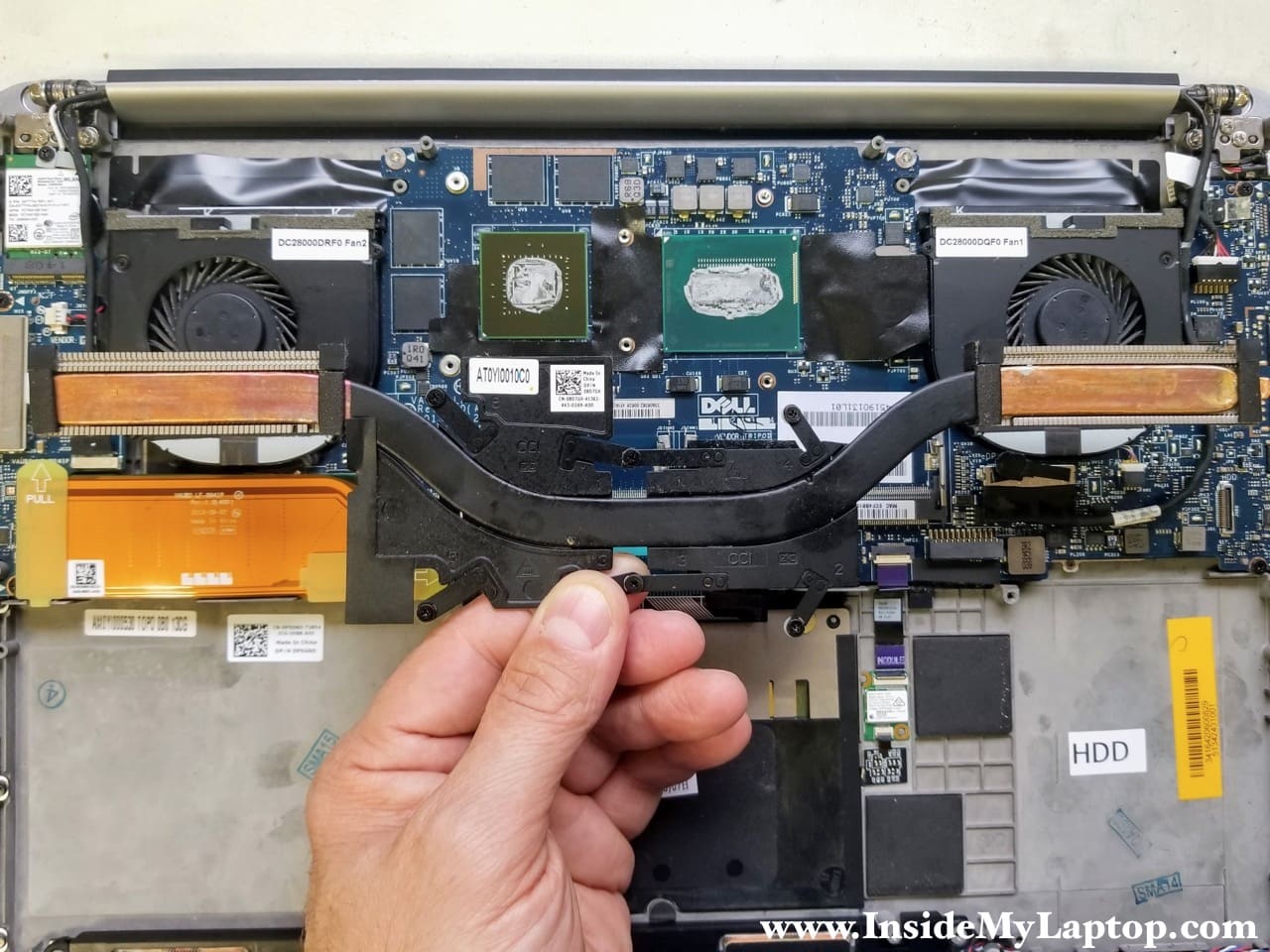
STEP 8.
Lift up and remove the heatsink. Now you can replace thermal grease on the CPU and GPU chips if necessary.
NOTE: you should be able to remove both cooling fans, as it shown in the following steps, without removing the heatsink.
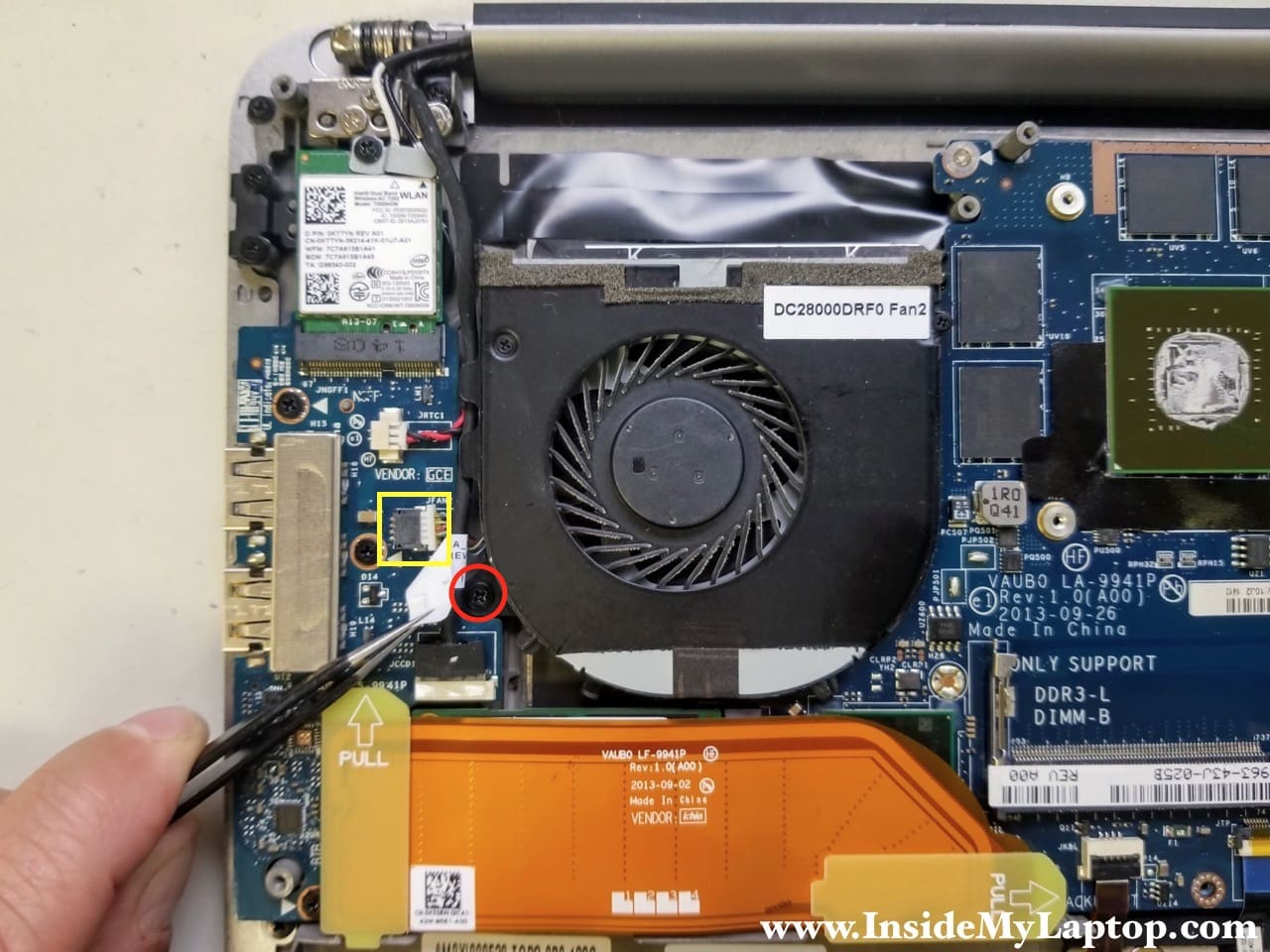
STEP 9.
Remove one screw securing the right cooling fan #2. Disconnect the fan cable from the motherboard.
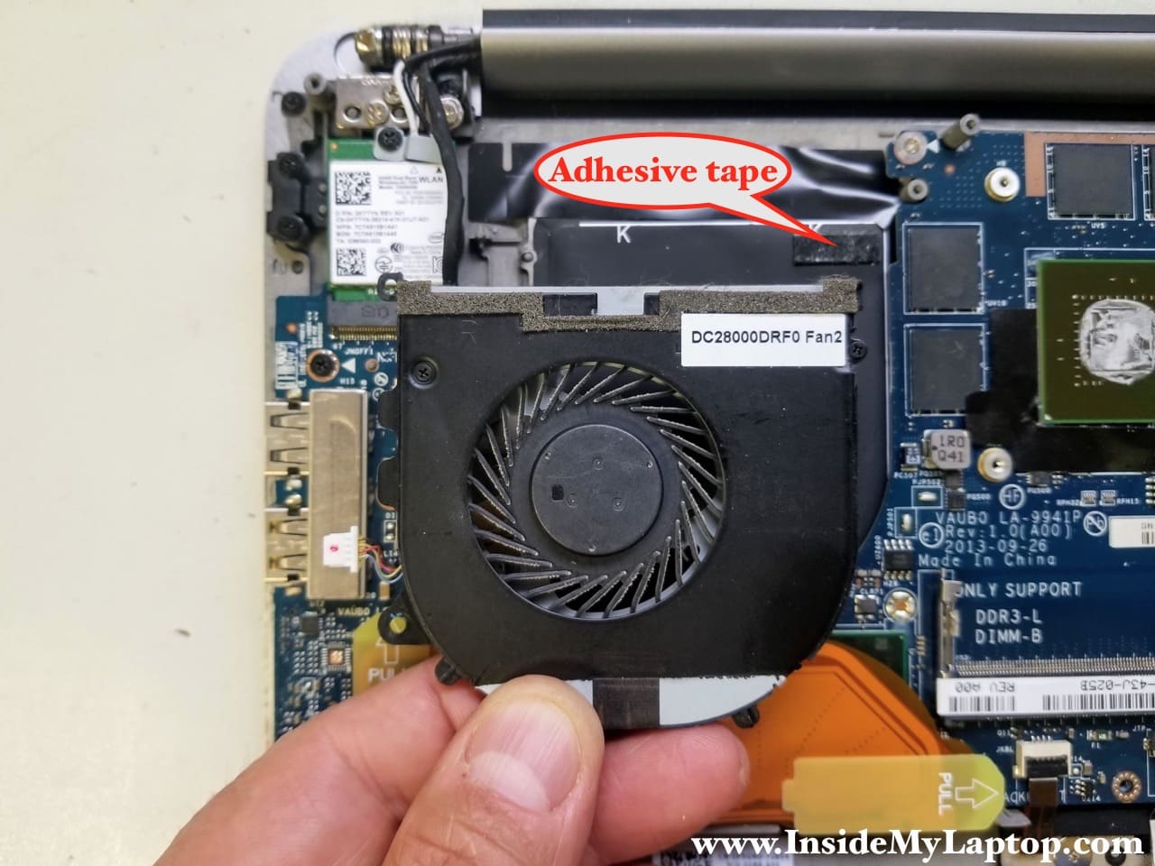
STEP 10.
While removing the fan, you will have to un-route the touch screen cable from the left side of the housing. It’s necessary to apply some reasonable force to separate the fan from the top case because the fan is secured by adhesive tape underneath.
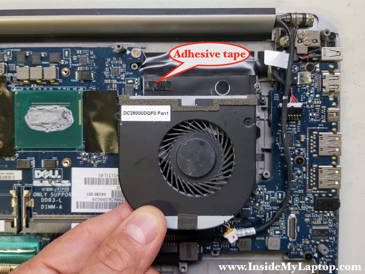
STEP 11.
Remove one screw and unplug the cable for the fan #1.

STEP 12.
While removing the fan, un-route the display video cable from the right side of the housing.
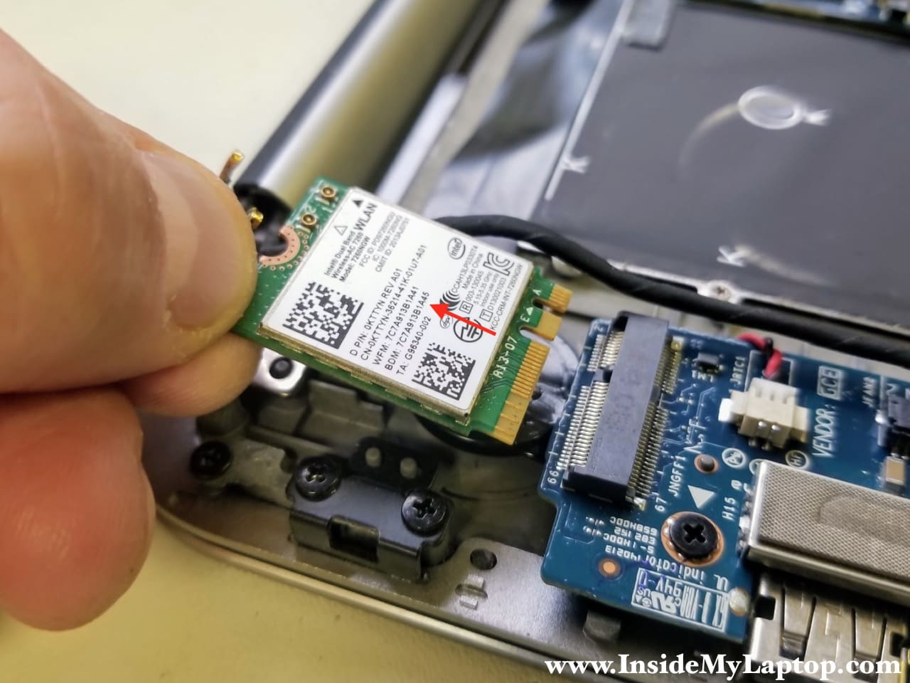
STEP 13.
Remove one screw from the WLAN card bracket. Disconnect both antenna cables from the WLAN card.

STEP 14.
Pull the WLAN card out of the socket and remove it.
STEP 15.
Disconnect the I/O cable from the USB SD card reader board.
Disconnect the I/O cable from the motherboard.
Remove the cable.
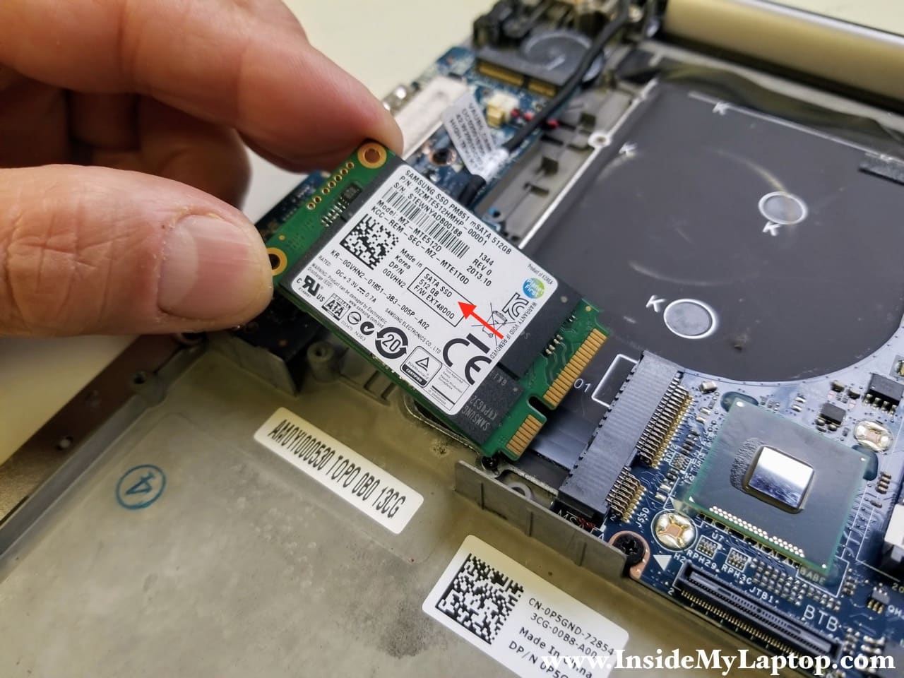
STEP 16.
The mSATA SSD drive located right under the I/O cable.
Remove one screw fixing the SSD to the top case.
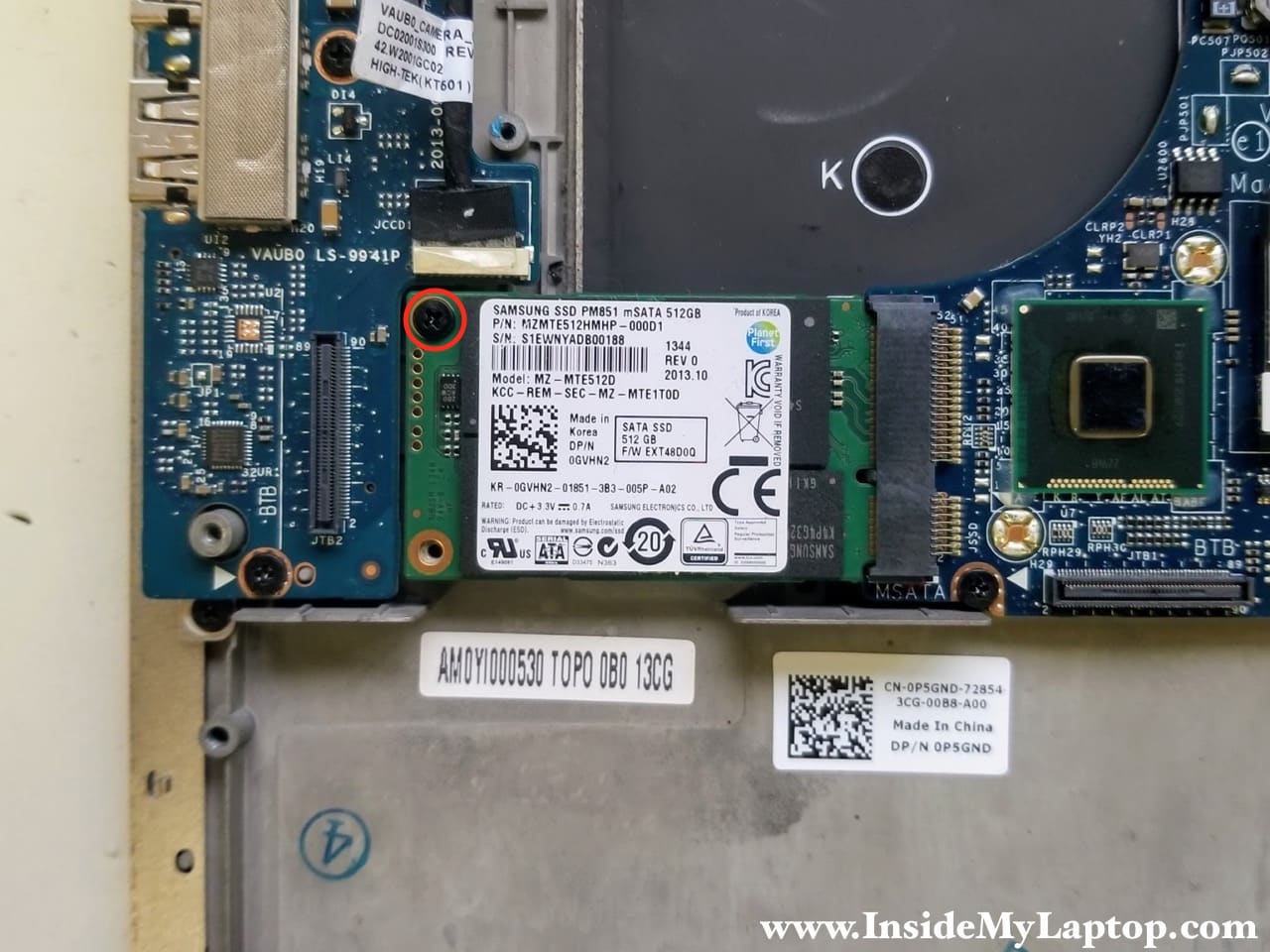
STEP 16.
Pull the SSD out of the slot and remove it.
STEP 17.
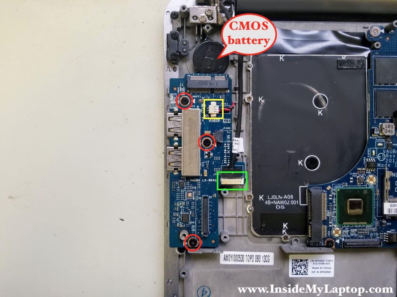
If you didn’t notice, the CMOS battery is located right under the WLAN card which we removed in the step 14.
Remove three screws from the USB SD card reader board.
Disconnect the CMOS battery cable (yellow square) and touch screen cable (green rectangular).
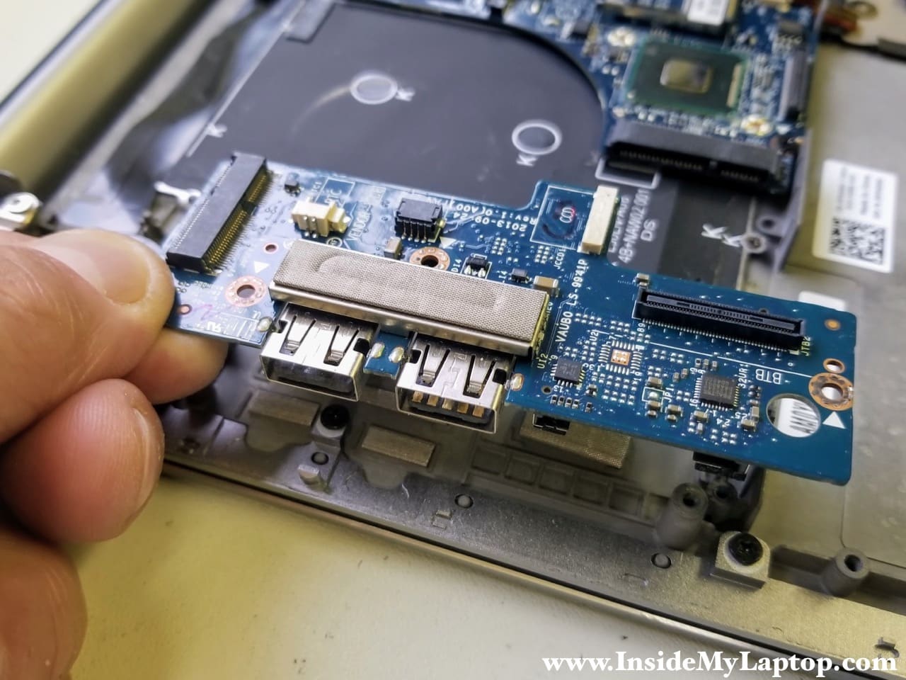
STEP 18.
Remove the USB SD card reader board.
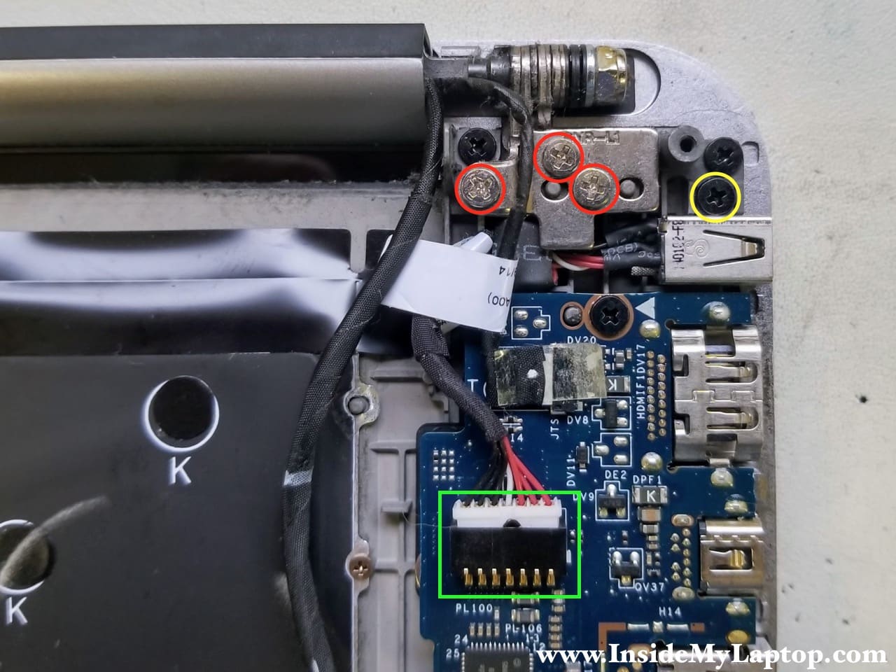
STEP 19.
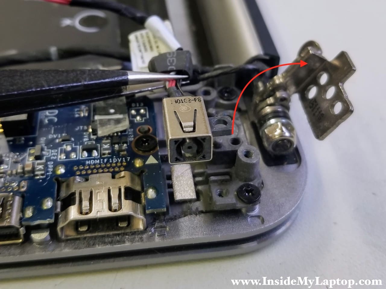
The DC-IN power jack cable routed under the left hinge.
Remove three screws securing the hinge and one screw securing the DC-IN power jack.
Disconnect the DC jack cable from the motherboard.
STEP 20.
Open up the left hinge and remove the DC jack from the housing.
STEP 21.
Loosen up two screws on the top (yellow circles). They will remain attached to the motherboard.
Remove four more screws (red circles).
Disconnect the following cables:
- Keyboard backlight cable (red square)
- Touchpad cable (small yellow square)
- Keyboard data cable (green rectangular)
- NFC module cable (large yellow square)
- Display video cable (purple rectangular)
- Speakers cable (blue square)

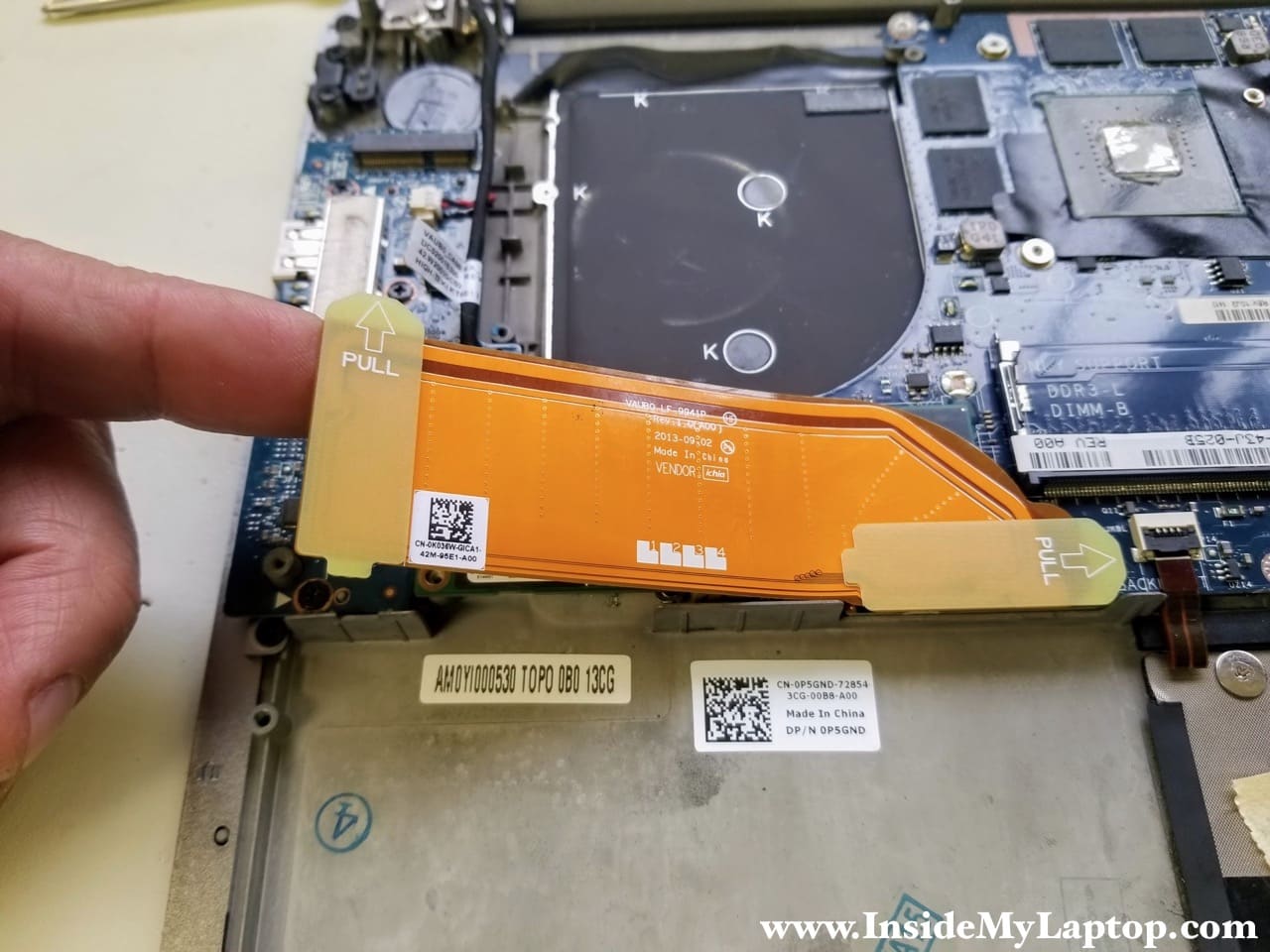
Here’s how to release small flat cables.
Unlock the connector by lifting up the locking tab. Pull the cable out of the connector.
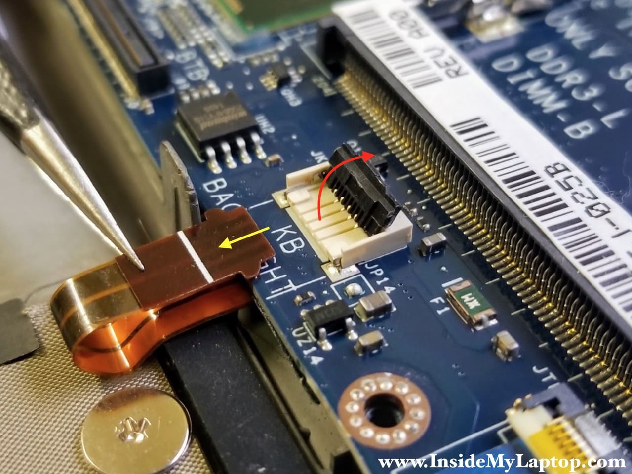
The keyboard cable can be released the same way. Unlock the connector and pull the cable out.

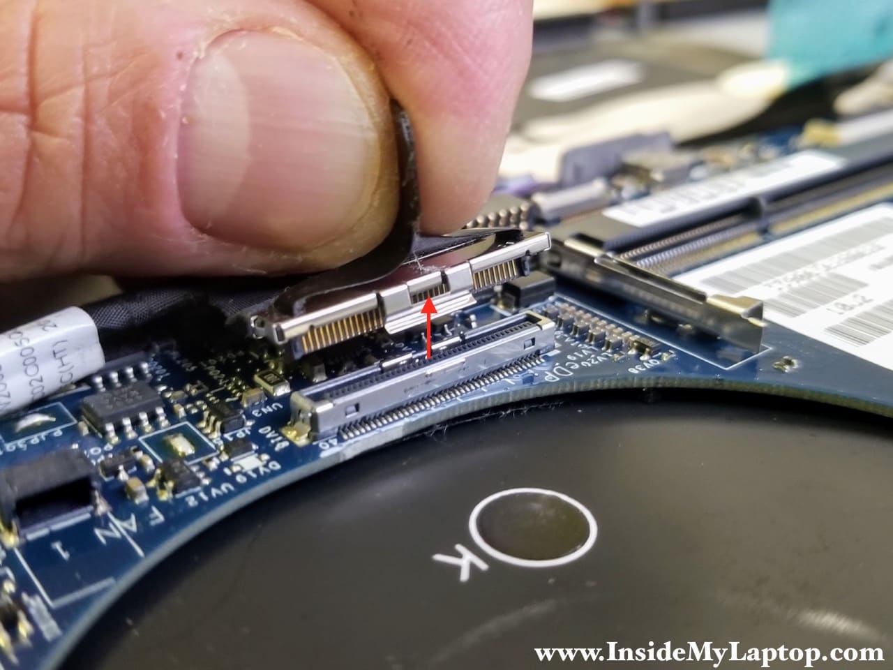
In order to disconnect the display video cable you will have to pull the connector up using the black belt on the top.
STEP 22.
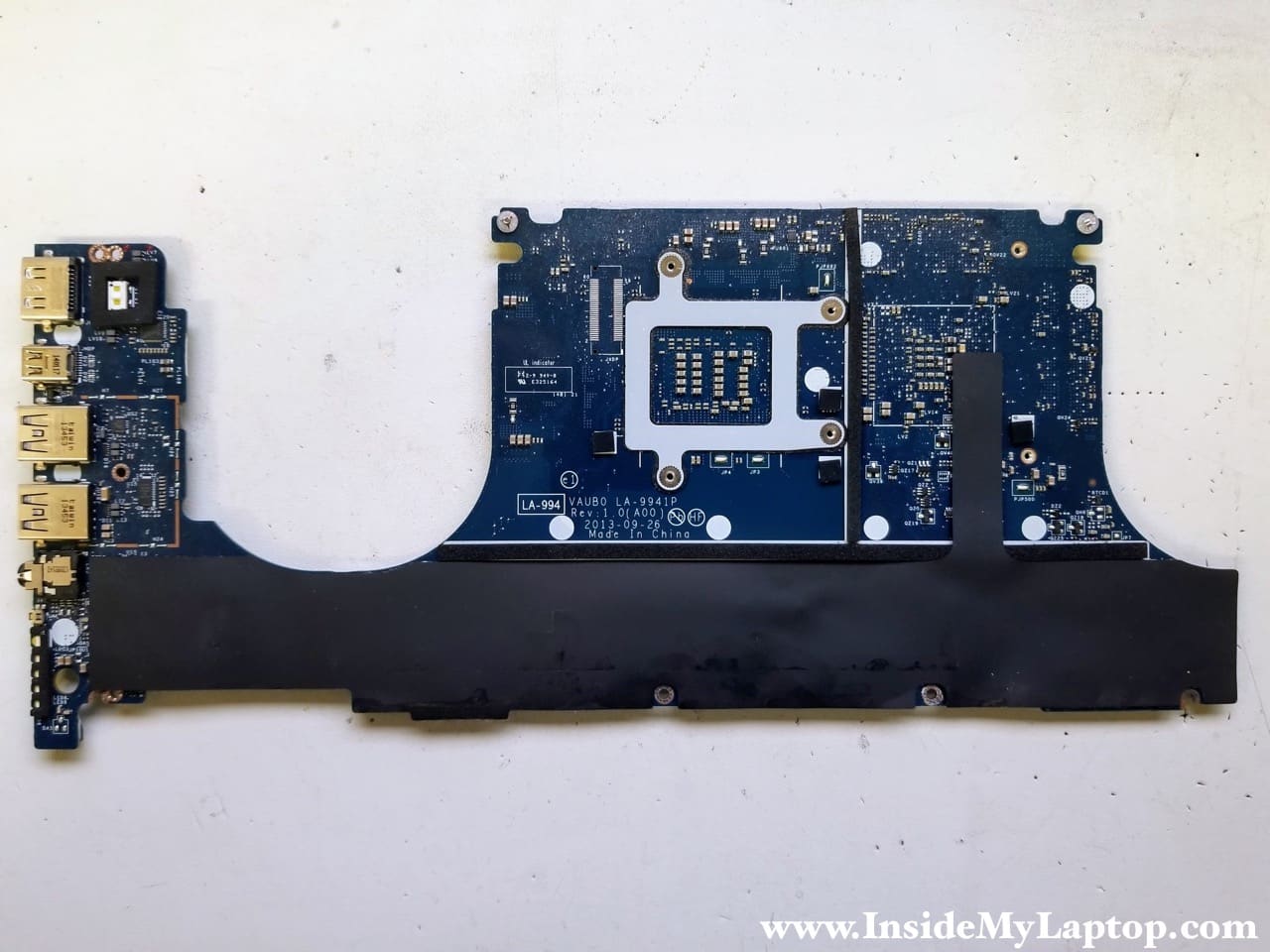
Now you can separate the motherboard from the top case and remove it.
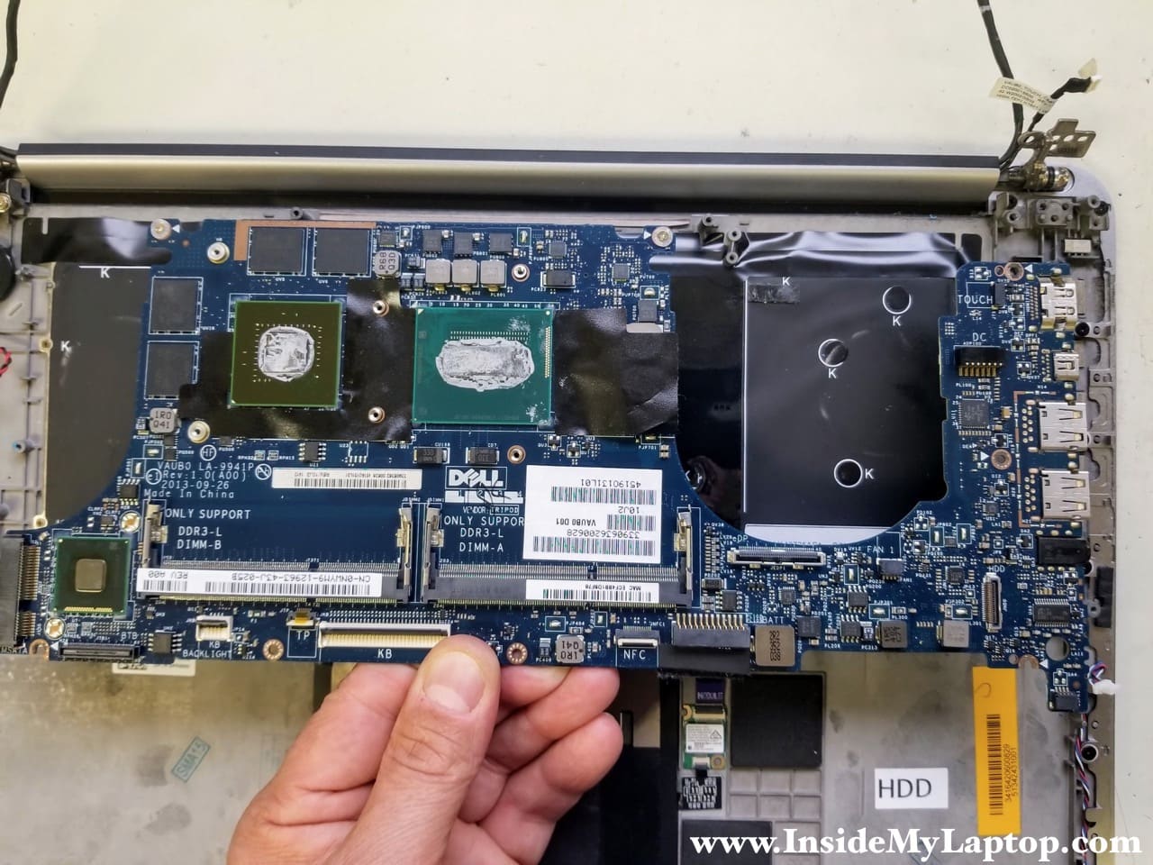
Here’s the back side of the motherboard.
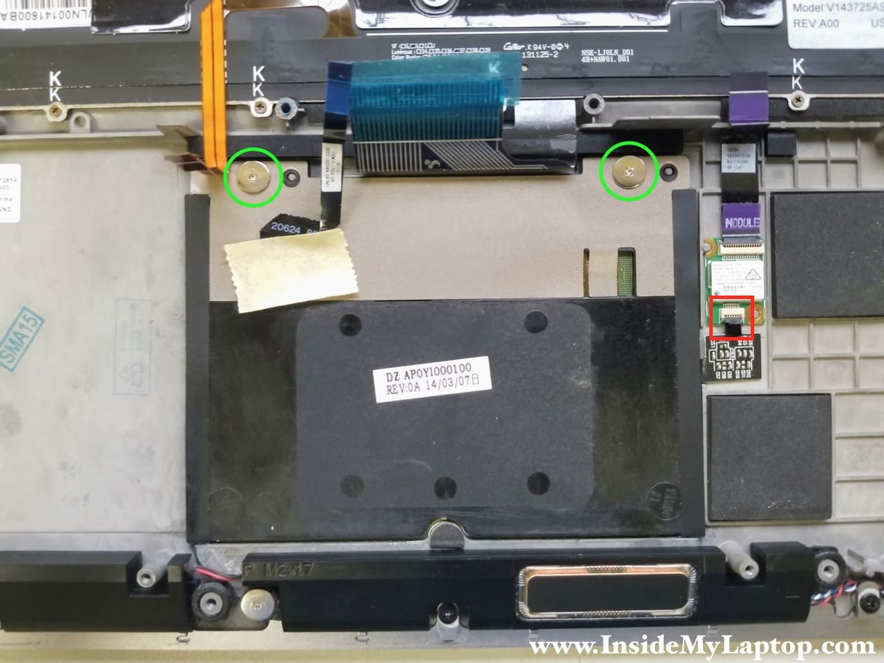
STEP 23.
Remove two silver screws securing the touchpad.
Disconnect the cable from the NFC module.
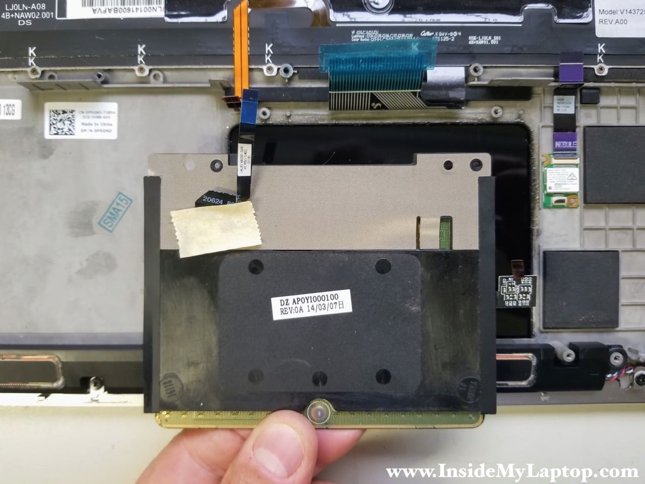
STEP 24.
Remove the touchpad.
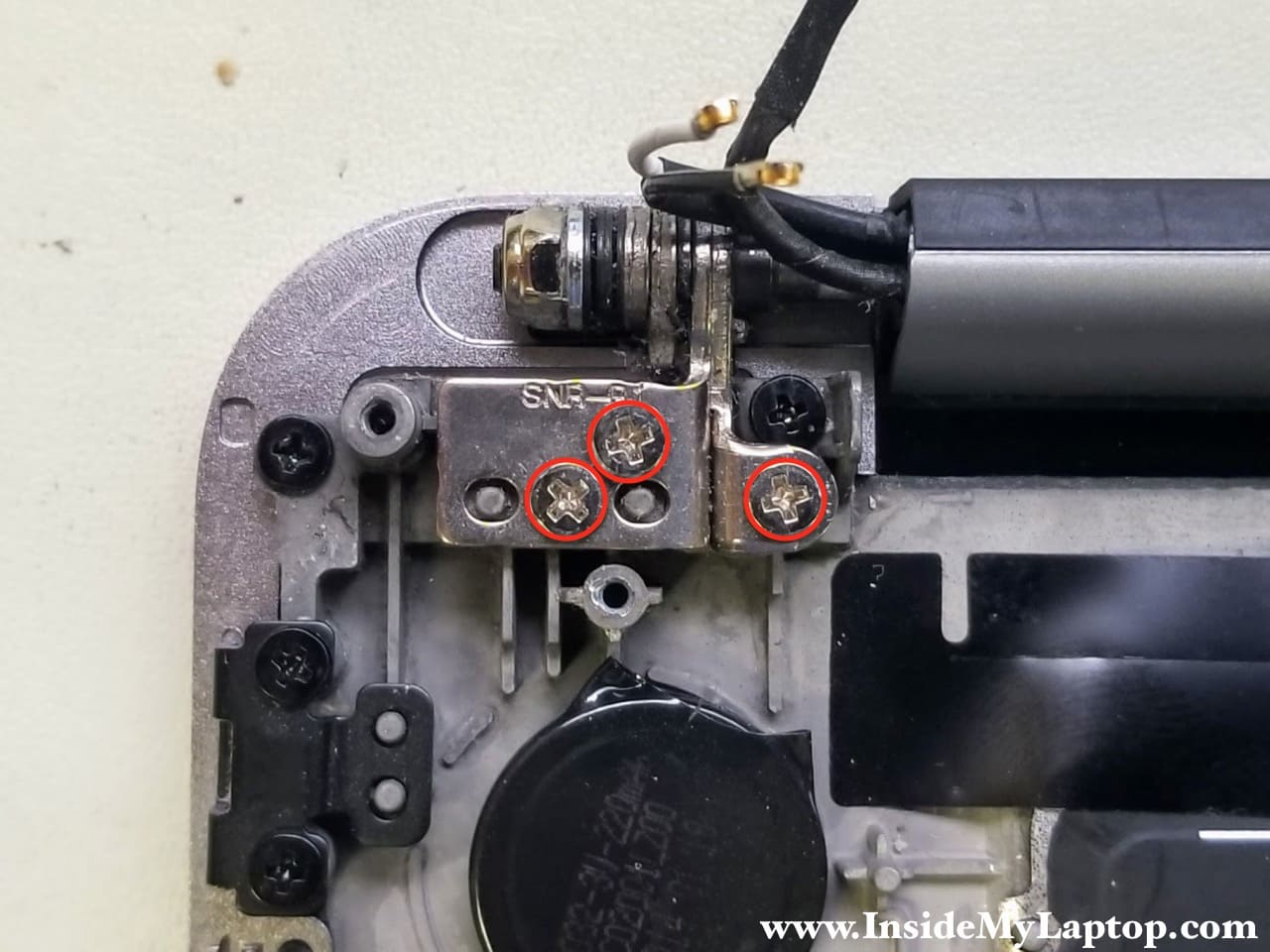
STEP 25.
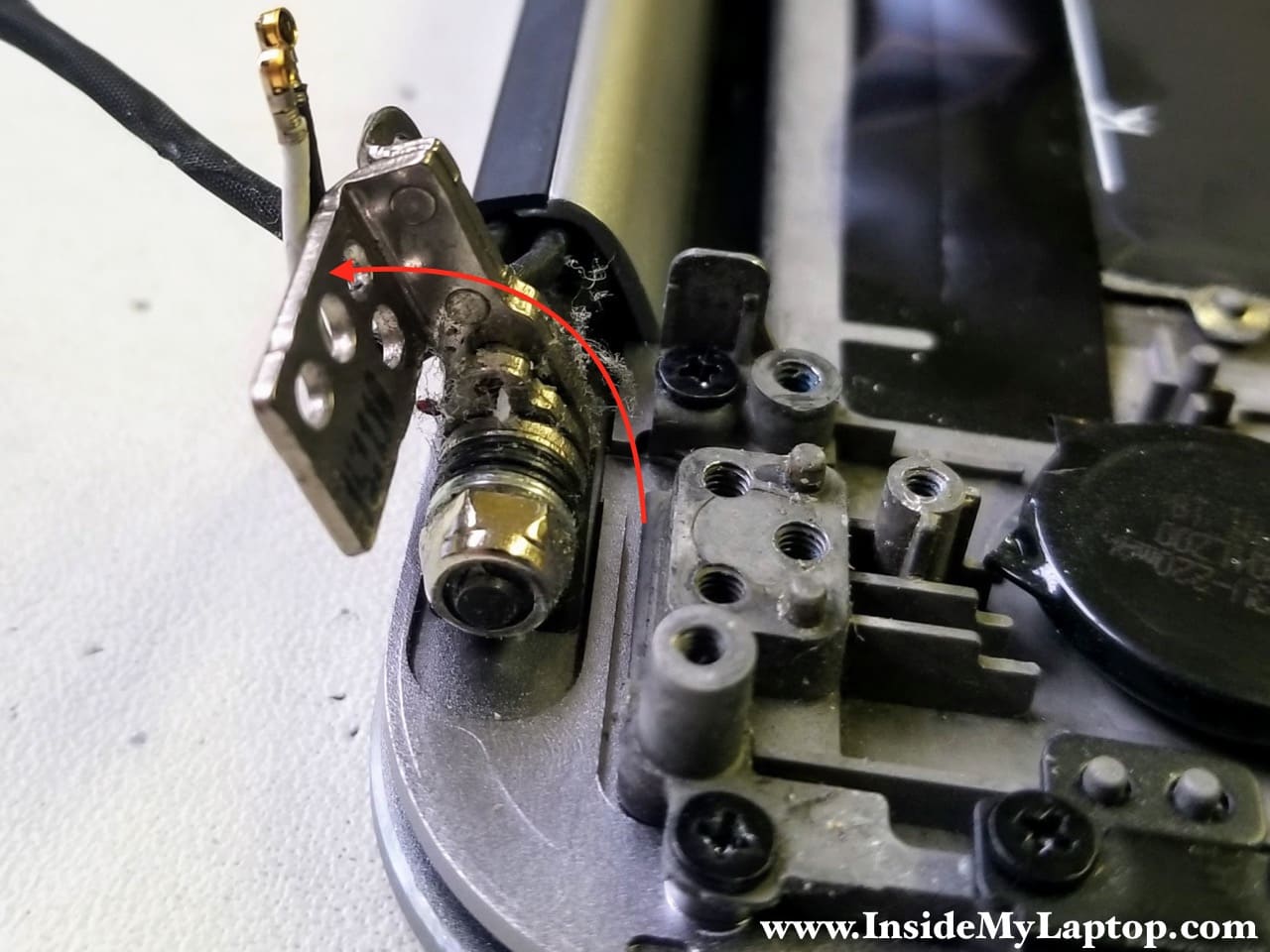
Remove three screws securing the right hinge.
STEP 26.
Open up the right hinge. As you remember, the left hinge was opened up in the step 20, when we removed the DC power jack.
STEP 27.
With both hinges opened up, you can easily separate the top case assembly from the touch screen display panel.
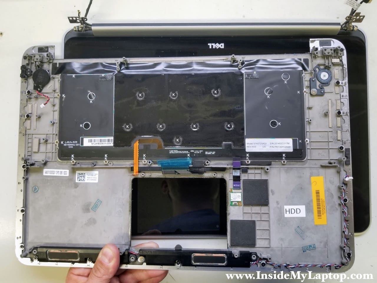
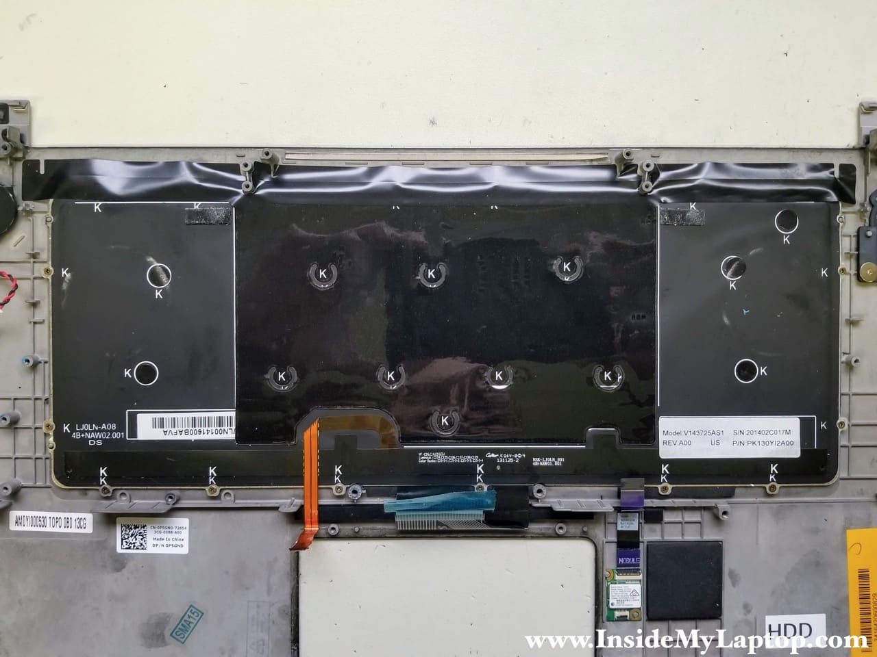
In order to remove and replace the keyboard you will have to remove many small screws marked with the letter “K”.
After that the keyboard can be easily separated from the top case.
Ted H.
Hello. Nice website. It’s used as a guide in the IT department of Princeton University.
Looking for a replacement Heat Sink Fan assembly for a old Sony Viao Model PCG-7312L
VPCEB3AFM SN = 27528433 3015900 Service Tag = C606MZM2
Since Sony doesn’t make computers anymore, aside from eBay, might you have a site suggestion for obtaining parts for Sony’s? Thank you very much.
IML Tech
@ Ted H.
I think this one from Amazon will work: https://amzn.to/2OIT9wr
Also, you can try searching by the fan model: “Sunon GC057514VH-A”
Compare the picture with your fan and if it looks identical, most likely it will work.
I don’t know any good supplier for Sony parts.
Biologiemodellmacher
Tags Dell Dell Laptop Repair Dell XPS Repair Manuals P31F001 Removal Video XPS XPS 15-9530 how to installation laptop touchpad