In this guide I’ll disassemble an Asus N53S laptop. My target – fixing failed DC power jack.
Problem description: the battery started charging intermittently. Moving the power plug inside the DC jack fixes the problem for a while but eventually it fails again. The battery didn’t charge with another AC adapter either.
In Asus N53S the DC jack is soldered to the power board. This guide explains how to access and remove the power board.
Before you start, make sure the laptop is turned off.
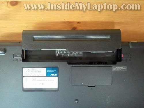
STEP 1.
Remove the battery.
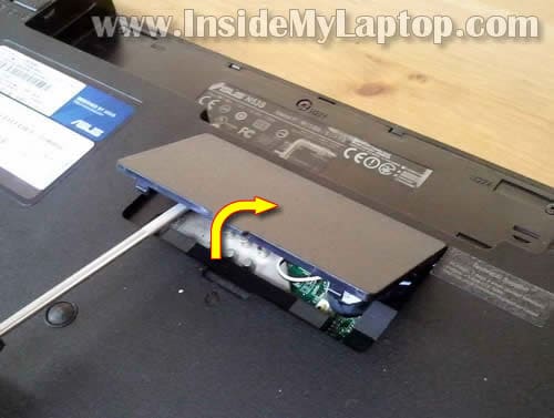
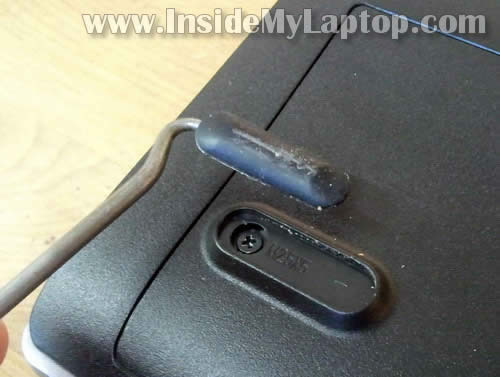
STEP 2.
Using a small screwdriver lift up and remove the bottom cover.
STEP 3.
There are four rubber feet located on the bottom.
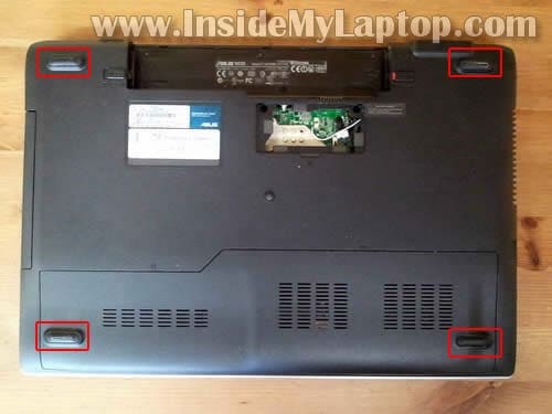
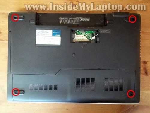
STEP 4.
Remove all four feet with a sharp object.
STEP 5.
Remove four screws found under rubber feet.
UPDATE: as it was mentioned in the comments, I think I forgot to show screws located in the battery bay. Pay attention to that. Remove them too.
STEP 6.
Slide the hard drive/memory cover and remove it from the bottom.

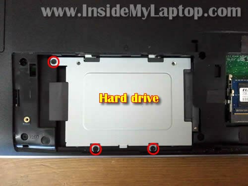
STEP 7.
Remove three screws securing the hard drive assembly.
Slide the hard drive assembly to the left to disconnect the hard drive from the motherboard.
It’s not necessary to remove the hard drive assembly for the purpose of my guide. You can leave it connected to the laptop.
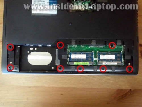
STEP 8.
All four memory slots located under the same bottom cover. It’s not necessary to remove memory modules for the purpose of my guide.
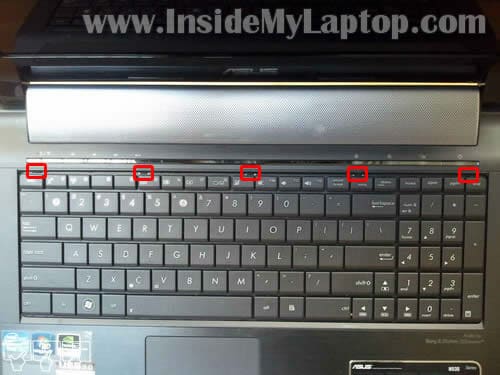
STEP 9.
The keyboard secured by five spring loaded latches on the top.
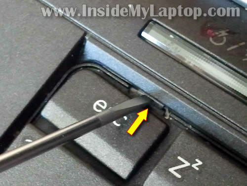
STEP 10.
Push on the latch with a small screwdriver and at the same time lift up the keyboard a little bit.
When the keyboard is lifted, it will not allow the latch to lock again.
Do the same with all remaining latches.
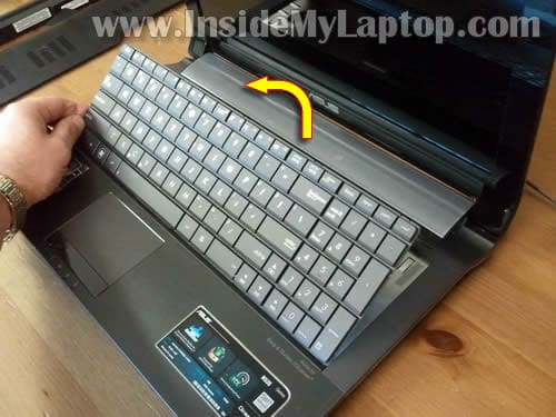
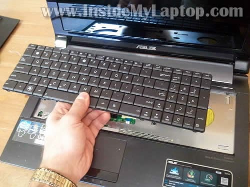
STEP 11.
After all latches released you should be able to lift up the keyboard and place it upside down on the palmrest.
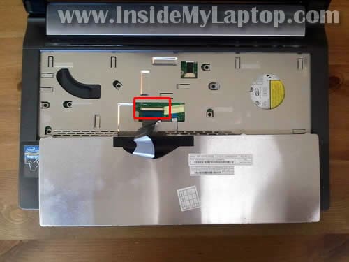
STEP 12.
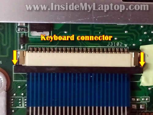
The keyboard cable connector located under the keyboard.
You’ll have to unlock the connector and release the cable before you remove the keyboard.
STEP 13.
In order to unlock the connector move the brown locking tab about 2 millimeters to the direction shown by two yellow arrows.
STEP 14.
Pull keyboard cable from the connector.
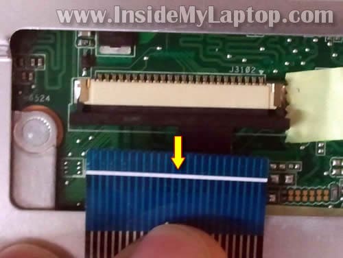
STEP 15.
Now you can remove the keyboard.
STEP 16.
Remove seven screws securing the top cover assembly.
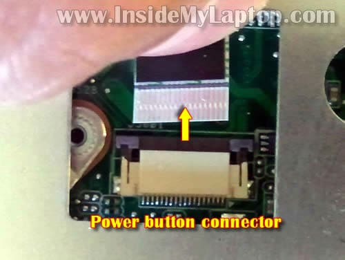
Disconnect the touchpad cable (left) and power button board cable (right).
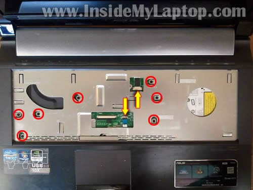
STEP 17.
Unlock the power button board connector same way you unlocked the keyboard connector.
Remove cable from the connector.
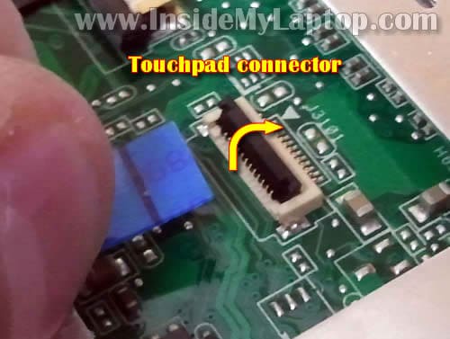
STEP 18.
Here’s how to unlock the touchpad connector.
Lift up the left side of the brown locking tab with your fingernail. The tap will open up at a 90 degree angle.
After that pull the touchpad cable from the connector.
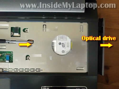
STEP 19.
One of the top cover screws also secures the optical drive (DVD drive).
Now you can remove the drive.
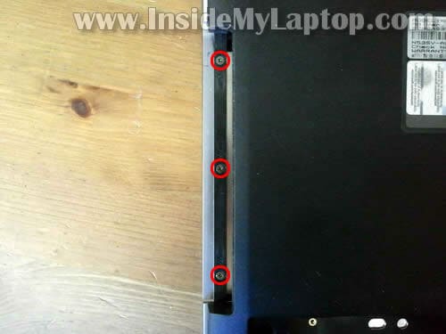
STEP 20.
Don’t forget to remove three screws from the optical drive bay.
STEP 21.
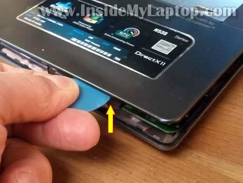
After you removed all screws from the bottom of the laptop and top cover, you can start separating the top cover from the bottom.
You can use a piece of soft plastic to separate these parts.
Continue removing the top cover assembly with your fingers.
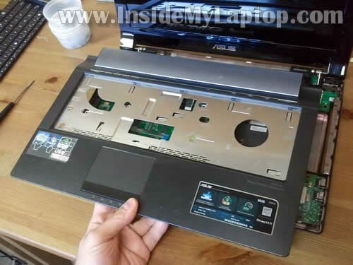
STEP 22.
The top cover assembly removed.
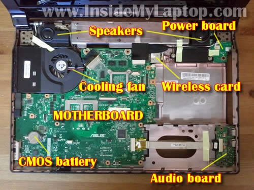
STEP 23.
Under the top cover you’ll get access to the following internal components:
– speakers
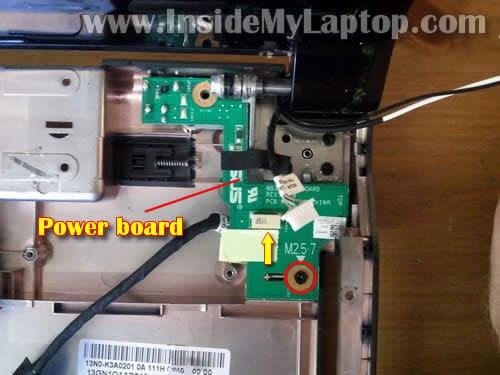
– power board
– cooling fan
– wireless card
– CMOS battery
– audio board
– motherboard
STEP 24.
Disconnect the power board cable from the motherboard.
Disconnect both antenna cables from the wireless card.
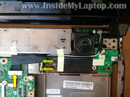
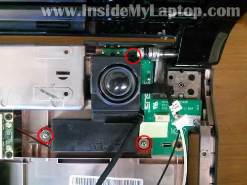
STEP 25.
Remove three screws securing the right speaker.
Lift up and remove the speaker.
STEP 26.
Remove one screw securing the power board.
Diconnect cable from the power board.
STEP 27.
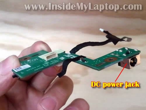
Now you can remove the power button board from the laptop base and repair or replace the failed DC power jack.
The DC power jack soldered to the board but it can be replaced.
teadict
Thank you! Thank you! Thank you! Thank you!
This site is of those where professionalism rules and I likes that.
Thao
can u upgrade the processor on this computer ?
i wanted to upgrade to i7
IML Tech
@ Thao,
Asking about Asus N53S laptop?
Most likely you can. If you google “Asus N53S specs” you’ll see that many of them cove with Core i7 processor.
John T.
Hi, Is the procedure to repair the k60 series notebooks similar to this guide?
John T.
Meant to say “is it the same to repair DC jack in the k60 notebooks”
IML Tech
@ John T,
I’m not sure if all steps will be exactly the same but probably very similar.
I have partial Asus K series laptop disassembly instructions here: https://www.insidemylaptop.com/disassemble-asus-k-series-notebook/
Hopefully both guides will give you the idea how to take it apart.
John T.
Thank you!! I took it apart using both websites and I’m having trouble getting the top cover off around the hinges and near the touch pad still…..will I have to remove the screen and hinges I didn’t think I would…the edges of the cover came up no problem…I can see the dc jack and it’s sooo close it doesn’t appear to be soldered either so once I get in it should be an easy fix…thanks JT
Marcelo
Thank you! I have no words to say how much you helped me! My notebook is alive again!
kurogane
thanks you this web very helpfull, can i use that way for laptop N43SL series because look like simillar. can u help me i have N43SL i7, the right speaker have problem sometime sound like “crack” but go back normal again in hour, what must i do? must change new right speaker or can u help me to fix that
Best Regard.
IML Tech
kurogane,
Test your laptop with headphones. If the right headphone speaker also has same intermittent “crack” problem, this could be audio card/motherboard issue.
If headphones work properly and the problem appears only with the laptop speakers, most likely the speaker itself going bad. You’ll have to replace it.
kurogane
thank this web is the best ever, good blees u
chang
In the step 2, before you remove the small cover, there is a screw on the side (in the side wall of battery bank) needs to remove first. Otherwise you will damage the cover.
IML Tech
@ chang,
Are you sure about that? I don’t remember removing this screw. Maybe I just pulled the cover without removing the screw? 🙂
Anyone can confirm that this cover has a screw on the side?
Rajesh
Hi, my Asus Laptop N53S that i bought only two months ago is acting very weird since last week. It’s whole body is like a sound mic. Wherever i touch, it feels like I am touching a mic and my touching sound is coming from the speakers. I also noticed that Speakers at full volume aren’t loud enough like they used to be. The mic noice in the laptop body is very annoying and i always have to put the volume low or mute. Please help me out. Thank you.
IML Tech
@ Rajesh,
It’s possible the microphone volume turned all the way up.
Click on Sound in the Control Panel. Click on Recording tab and then in Internal Mic.
Check Internal Mic volume level. Turn it down and test the laptop.
Rajesh
I don’t know who you are Mr. or Miss IML Tech, but thank you so very much, my problem is Solved! I asked so many people about this mic problem but no one could help me out and day by day it was getting worse but as you suggested to check the Mic volume- you were right. It was all the way up. Thanks a Million. God Always Bless You 🙂
Rajesh
@ Mr. Chang
Yes, my Laptop is Asus- N53S, i7, 16GB ram, 1TB Hard Drive, Windows 7 and MB Ver. :N53SV-BH71, has a screw inside the battery place on the side of the wall. I didn’t try to open the back cover because the laptop is under warranty but that screw is defenately there and its attatch to the hinge of that back cover.
Zolhof
Thank you SO MUCH! I took the power board apart and fortunatelly I just had to solder the original jack again (no need to buy another, in my case) and my laptop is working perfectly! Just a small note, on Step 17 there’s a screw just above the touchpad, kinda hidden under a silver stripe thing.. you won’t be able to lift the top cover if you don’t remove this screw.
Mitch
@Zolhof
Thanks for mentioning that screw. I almost missed it.
Adel
Hey there,,
thanks a LOT for that comprehensive work.. I’m impressed 🙂
what if I only wanted to take out the grill of the speakers in order to clean it ?? do I have to take the whole front cover off ?? because I’ve noticed from the photos that the grill is part of the front cover..
Behzad
hi,
i have a problem with my asus n53 ,today my laptop become wet by water, and i see that the back of keyboard has no way to drop water , plz help me how i can fix this?
can it be possible no water drap in mather board?become patient and take my laptop in light can help me to fix?
plz help me and tnx 4 ur great website…..
Quincy
ohhhhhhhh thank you. finally some awesome person cares.
Lars Jørn Nissen-Schmidt
Thank you very very much – it worked perfectly!
Like someone before me – I repaired the broken mini jack plug by soldering a copper wire to the mini jack center pin and around the edge of the print to where it is originally soldered.
Rimmel
Asus N53J there’s no screw here, just pull up the small cover.
Thanks very much for help! 🙂
Allan
Thank you very much for the tutorial! It fixed my DC Jack
But I accidentally broke the locking tab of the touchpad connector and it hasn’t worked without that little plastic part (no matter how many times I try to reseat the ribbon cable)
PLEASE, CAN SOMEBODY HELP ME??? 🙁
chan
theres screws under the battery compartment and 2 screw inside the memory compartment that needs to come off also to seperate the front panel from the back. — also as mentioned above the screw over the touch pad on step 16 ( 8 screws instead of only 7) — other than that this posting works great to resolder the main pin from my power jack. ( somehow there was a crack in the solder connection)
Bratek
Thanks for your works!
I have question?
This laptop can upgrade full HD monitor ?
(from 1366×786 to FULL HD led backlight (1920 x 1080)” ?
rems
Thanks for the detailed instructions!
I also have the headphone jack broken. Is it as easy to fix? Do you know which part I should buy and where?
IML Tech
@ rems,
I believe the headphone jack is located on the USB/audio board shown in the step 23. If the jack is broken I think you’ll have to replace the entire board unless you can find the headphone jack itself and replace it. Replacing the headphone jack requires soldering skills.
I’m not sure where you can buy this part.
Niek
Hey, when I want to remove the cover it seems to be stuck somewhere by the speaker part. I removed every screw! should I use force or do I have to take care of something?
By the way, I accidently broke one of the white locks of the power ribbon cable and it’s not working now, atleast, I can’t put it in. Maybe with the top cover removed I can but its hard..
IMLizKing
Thanks much for the instructions…
As noted above, there is an 8th screw on step 16, under the silver/foam strip at the bottom edge.
You don’t seem to mention removing the 5 screws in the battery compartment, which do need to be removed.
In step 7, if you don’t need to take the hard drive out, you can keep the upper left screw in place–it doesn’t go through to the front panel (but the lower two do.)
The screw at the top of the speaker assembly (Step 25) is a M2.5x7mm. This is the only one that doesn’t have clear markings about what size it is. I made the mistake of thinking it was a 10mm and didn’t realize my mistake until I had my laptop nearly all back together (with 1 less 10mm and 1 extra 7mm!)
Also, when re-assembling please pay attention to the placement of the DC power board–my first time putting it back together I misaligned the switch with the external wireless switch cover/doohickey and had to take it all apart again because I couldn’t turn my wireless on! So make sure the switch moves before putting the whole thing back together.
Thanks again for the instructions! I’m sure I could have done it without, but it’s very nice to know how it’s all put together BEFORE tearing it apart so I don’t end up snapping some piece of plastic because I forgot to remove a screw or didn’t know where or which way to pry things open.
Marcleduc
I did everything as explained here and stoped juste before disconnecting the keyboard, put everything back in place and now the screen will not turn on 🙁 what to do???
Jack
@ Marcleduc Im having the same problem anyone have a fix? I tried replacing the wifi card and now the screen isnt turning on.
Marcus
Någon som vet var man kan beställa/köpa ett nytt power board?
Paul
So I have an issue that I’m not quite positive on. I replaced the part, and got it all back together and working again, but now my laptop seems to hover on charging, eventually dwindling to nothing and shutting down, rather than charging back to full. I’m wondering if maybe I messed up on placing the part correctly or something… or if maybe the part I used was a faulty one, or one for the wrong model. I use a n53s, and the part was for the n53sv if I recall… I double checked and compared parts to the one I was taking out, and the numbers matched and everything, so I would have thought it would work fine… But it isn’t providing enough power. Any ideas?
Arnold
Hey thanks.
This tutorial helped immensely.
There are a few screws I had to remove that you didn’t list though.
two in particular under the first cover you had me remove.
Thanks again
AFB
JonasLB
Thanks! Everything is now working perfectly on my computer. I soldered the new power jack on my self, but it took quite some time. I would recommend buying an entire power board instead of just the jack. It costs a bit more, but will save you the hassle of soldering.
Also, as others mentioned here, there are more screws than shown that need to be removed.
H2 professpr
just a note of thanks for these instructions. what a lifesaver.
Keyur
My dc adapter seems like not working properly. Does anyone know from where I can buy it. I called asus and they said I need to replace whole mother board to fix it.
Max
like @ Marcleduc and @Jack, I replaced my wireless card and now cannot get the laptop to function. The lights turn on, but the screen doesn’t. Desparate for advice here, can’t find anything online.
Reid Randell
A fantastic description and illustrations.
In addition to the above, you must remove the 5 screws from the bottom of the battery compartment.
In step 16, there are 8 screws to be removed, rather than just 7. The 8th screw is located near the center at the bottom of the little square opening where you can see the circuit board. On mine, there was a small piece of foam covering the screw head.
I performed this procedure (with the above additions) and my laptop is as good as new.
Lisa
Thank you, these instructions were great! Also thanks to other commenters who mentioned other screws not in the original instruction set.
Richieb213
Instructions definitely helped, but yes note there are a few more screws not mentioned (they have been by previous commenters)…replaced my DC board and the laptop is as good as new
Ediel
Man, Thanks for the tutorial!!! I used this clean my laptop and replace the wireless card for a Centrino Advanced 6200 AGN, but it doesn’t work. Now the device manager shows the ERROR 10.
I want use this card to be able to use 5GHz band, but I needed to replace to de older card (Centrino 1000) because of the error.
Someone knows how to resolve this???
Steven Lee
Hey,
I tried out your guide and my laptop is working like a charm again! Thanks a lot! 😀
Matt
When I plugged in my laptop the other day, sparks came out the laptop’s power socket and it smelled like it was burning. It won’t turn on anymore and when I plug in the charger to the wall, the green light on the power brick is on until I plug it into the laptops power socket. Do yointhink this would be the problem or is it something different?
Rickard
Anyone have any info about the dip switch setting on the dc powerboard?
K
Ok so I brought my Asus in a repair center and I got my power jack fixed. However, my wifi’s signal has become weak and I’ve been disconnecting to it frequently. Is it possible that the repairman did something or damaged the wireless card? I already asked the repairman about this, but he only said that the wifi is far from the charging port.
IML Tech
@ K,
I would ask him to double check if both antenna cables connected properly to the wireless card.
The antenna cables shown in the step 24 – two green arrows. Maybe he forgot to connect one of the cables back to the card after the power jack repair.
Ola Einar
Perfect guide, just repair my son´s PC
There missing a comments on removing screws on botton panel(2) and under the battery(4) but all over thanks for your guide
Nathan
Those of you who have the problem where the laptop won’t turn on after putting it back together, I had the same problem but it turned out that my RAM stick (memory module, step 8) wasn’t plugged in all the way. You have to put it in at a ~30 degree angle, and push harder than you think do before it snaps in to place.
K
Hi, thanks for your answer. I brought it back to the repair center and yeah, the antenna cable wasn’t properly attached. But, I have another problem .. today, the charger is properly plugged in to the laptop but after some time it will prompt that the laptop is in battery mode, and will then switch to ac mode without me doing anything. I just got it repaired last July 10. Is the power jack loose again?
jon
Hi, had the same screen-won’t-turn-on-problem as a couple of other guys.
Is it possible that this is caused by the replacement of the DC-board?
Does the DC-board power the screen separately from the motherboard? (hard/disk drive and the processor seems to get power, don’t know about sound)
Can frying the DC-board black the screen pemanently?
Anyhow thanks for a great guide.
-jon
Alex
Best guide thank you! 🙂
Ordered and replaced the power board works like a charm.
Also when i put the computer back together i had the same problem where it would not turn
on
It was just the ram, u have to put the ram back in at angle and push so the clips snap into place
Luca
Thank you very much for your useful guide. I was freaking out because everything was ok but wifi was out. 15 minutes later since I switched on the wifi started and now it’s ok.
flink
Thanks this was helpful
Just a note on the cable connected for the touch pad it is a different lock. Then the others and I lost my little lock part. Found it eventually but took me 2 days
Sergio
Thx mate! Problem was solved within 30 minutes with your description and the DC power board.
Again thank you!
Greetings from out of the Netherlands
axol
Hi!
Great page.
I left my AsusN53Sm at the repair shop for just this problem. They replaced the dc jack and soldered it to the board.
Result: I can´t open my programs in windows 7 without the computer freezes up and I have to restart. I did that 12 times and then returned my laptop to the shop.
There answer: something is wrong with Windows and they want to do a clean boot and reinstall windows. When I first started it up after repair I got a request that the computer wanted to reinstall windows and I called the repairshop and they told me to close the window.
How did this happen? It worked perfect exept for the dc and now I have a useless computer.
Do you have an answer to this mystery?
Greetings
Anna
Rox
Wow, this was really helpful, thanks! I’d just like to mention you forgot about three screws. You missed one in step 12 (center bottom) and after step 2 there should be step 2a (unscrew two screws under plastic cover of step 2. Thanks again! 🙂
William Los Brazos
Done. Except for those forgotten screws (anyone will notice easily) it’s been a 30 minutes repair. I re-soldered it. Works perfectly.
Machisa
Excellent tutorial! After PC Direct quoted me a price of $120, explaining they would need to special order the part, I decided to tackle the repair myself.
Question. Rather than repair the jack I decided to purchased a new DC jack board. Is no soldering required? So how is the board attached to the motherboard?
Janet Magenta
Thanks for the assistance. Without this tutorial I would never have attempted the repair, however I bought the board on ebay, installed it and now the laptop is recharging steadily.
Just one question. The indicator lights for CAPS LOCK etc are not working. Obviously something is not quite correct. At what step of the process am I likely to be able to fix this and what should I be looking for?
IML Tech
@ Janet Magenta,
It’s hard to tell why it’s not working without testing the laptop with another keyboard. This could be related to:
– Bad connection between the keyboard cable and motherboard. Try reseating the cable.
– Failed keyboard. Try replacing the keyboard.
– Motherboard related failure.
Ian Mc
Thanks for putting this guide together. My laptop was having power outs generating repeated Kernel 41 errors. Once disassembled the problem was identified as a problem with the connection of the main lead coming from the back of the power jack. Once resoldered everything was hunky-dory again.
Ian Mc
Alex
Hi, I followed your tutorial and some YouTube videos to perform a cleaning to ASUS laptop, however when I try to turn on the laptop seems to start but nothing appears on the screen (black) I removed BIOS battery, checked all cables but it does not work, Can you help to know what happened.
Thanks
Clément
Thank you very much for this detailed guide (completed with the comments) ! I used it to clean my laptop, and didn’t had the black screen issue on boot
Mark D
Thanks so much for creating this guide and uploading it. Because of the clarity and the helpful comments of others I stretched myself and went through with it. I made one mistake with the touchpad connector and snapped it, despite reading all the other instructions carefully, this different one took me by surprise, (I did not read the instruction carefully).
No drama, I loath touchpads anyway and always use a wireless mouse.
In my case it looked too difficult to work out what needed soldering and the jack had been loose for a year or so maybe from a cord being pushed against a wall or something, and a new little board was only 25 dollars or so.
Probably took me an hour and a half all up, labeling screws in lids and writing little notes where I needed to, but I have it back together and it works Yea!!!
thanks again and good luck with your works.
ScottS
Thank you. This made the repair really simple, and my computer works again.
Air Wind
Is there any soldering required if I replace the whole power board?
I’m not very confident with the soldering bit.
Thank you. 🙂
Andrew Dale
I take my hat off to you, but I would not attempt this! Putting it back together would be a nightmare. I do simpler repairs. Q: Are Asus portable still as badly designed? This is such a common problem with them, it seems. I shan’t be buying another until I know they’ve improved the power connector.
Pablo Lopez
I tried to fix it but did not turn on, even when the battery is Charged. Do you think changing the dc board to a new, it works?
Janet Magenta
Hi, I did the repair and replaced the power jack board 6 months ago. It has been working fine until last week and the old problem has recurred (constantly flipping between battery and AC mode when I move the laptop or have it sitting in my lap). I have bought another board and plan to do another replacement, however is there anything else that could cause the problem that I should look for while the laptop is in pieces?
IML Tech
@ Janet Magenta,
This problem can be related to the DC jack or AC adapter.
Test the AC adapter with a voltmeter. If power cuts off when you move the power cable, probably it’s bad adapter.
Janet Magenta
Adapter seemed OK, so I replaced the power jack card. The new power jack seems to hold the input cable a lot more firmly – doesn’t move at all, so hopefully it will last as long as the laptop (3 + years so far, fingers crossed).
Unfortunately I lost wi-fi somewhere in the process. Took it apart two more times trying to fix that but could see absolutely nothing wrong, so ended up with a $15 usb wi-fi to keep the laptop going. I would suggest that having some kapton tape on hand would be a good idea. A couple of pieces I have moved in the course of 5 dissemblings would no longer hold so I have had to do the best I can with getting the various cables and connectors held down.
Thanks once again for all your help.
Jean-Luc
Thanks for this tutorial. I have a similar problem: the battery does not charge any longer, and the DC adapter does not provide any power to turn on the laptop.
I assume it is either the DC power jack or the power board. Isn’t it preferable to change the whole power board (especially if I am likely not expert enough to solder the power jack)?
Thanks.
Justin
I am having the same problem too, slowly losing responsiveness to power jack. have to wiggle it and set it just right for it to power.. Laptop is still great and would love to get another good year out of it but i’m not sure whther to try soldering or just buy this $15 board off amazon.
Col
I thank you immensely for your instructions. I blamed the power problem as the result of falling when a small, fragile table broke under the load of the laptop. When inspecting the power socket, I believe the centre connection was broken as a consequence of stress from manufacturer. I called Asus service and was merely told the case was clicked as well as the screws after which I subsequently could see screws under the keyboard had to be removed, but with no obvious way to remove the keyboard. Unfortunately, once freed, only a few of the keyboard retainers were re-usable. I’m a retired computer and electronics tech and like my Asus N53SV but, after a disastrous upgrade to W10, this was not a pleasant way to spend many hours.
Thanks again…
Senhor das Moscas
Thank you,
With your carefully detailed pictures, it was the most easy notebook I fixed for a brother-in-law.
In return he uncloged my toiled, I am so happy! 😀
Success to you
Dutchman
Thank you very much! I just bought a new powerjack, followed your instructions and the laptop is working again! Costed me 20 dollar for a new powerjack and totally about 1,5 hour work. Thanks!
Chaika Yurij
have Asus u56e – I burned this transistor (see photo ) and I do not see the marking on it. Could you tell me which transistor
photo go to – https://yadi.sk/i/rJ4FmXc7mefBE
Marty
you forgot about a screw in between steps 1&2 it is located from battery bay all and all i dont need to unscrew it anymore as i ripped it off
IML Tech
Hi Marty, thank you for saying that. I edited the guided and added your comment in the step 5.