Today I will be taking apart a HP Pavilion x360 13-a010dx Convertible PC. I will show how to teardown this Tablet laptop down to the motherboard.
By the way, both memory slots located on the bottom of the motherboard and it has to be removed in order to upgrade RAM modules.
STEP 1.
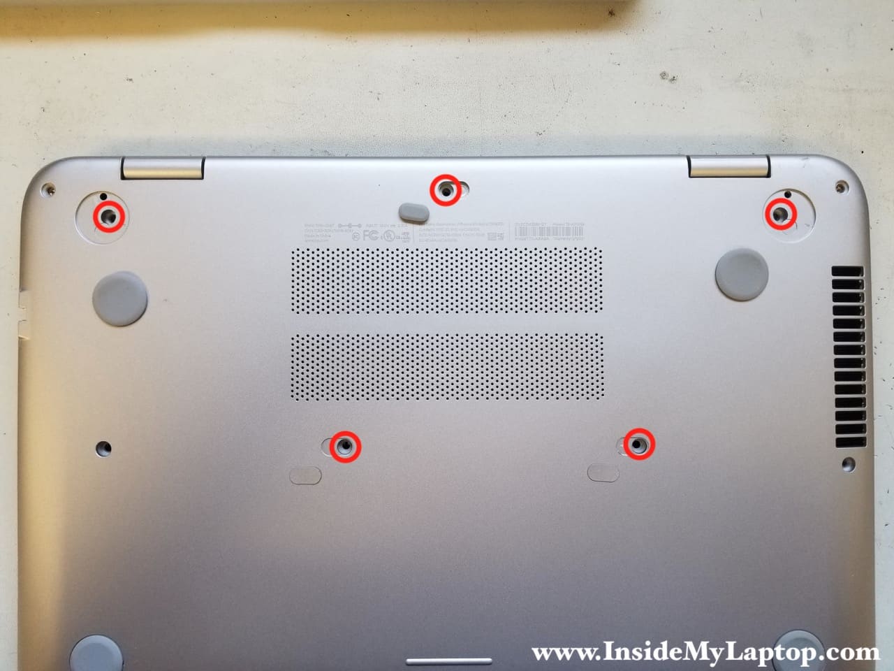
Remove all screws from the bottom case. Some screws are hidden under the rubber feet and plastic covers.
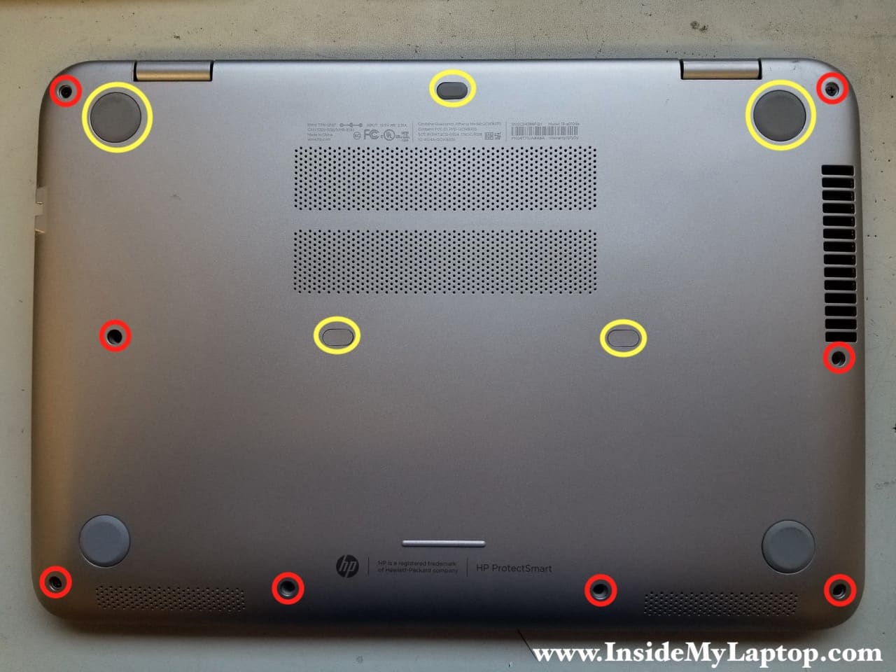
You can remove bottom feet and decorative covers using a needle nose tweezers.
Remove all hidden screws.
STEP 2.
Start separating the palmrest assembly from the bottom case using a plastic case opener or any other similar tool.
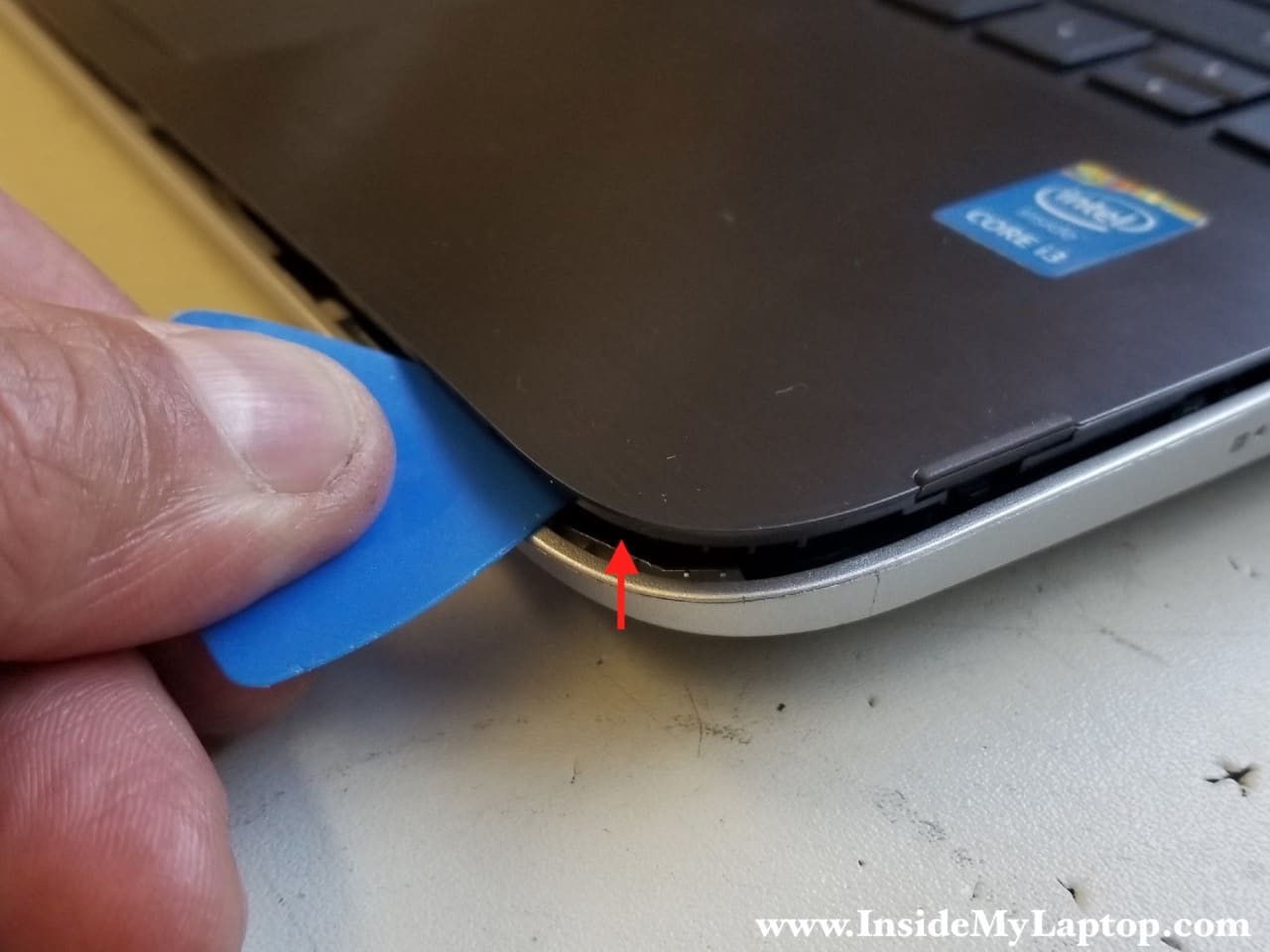
Continue separating the palmrest from the bottom.
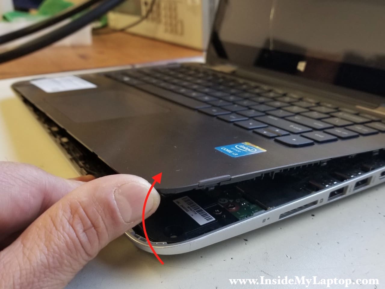
STEP 3.
Be careful removing the palmrest. There are two cables connected to the motherboard.

Turn the palmrest assembly upside down so you can access the cables.
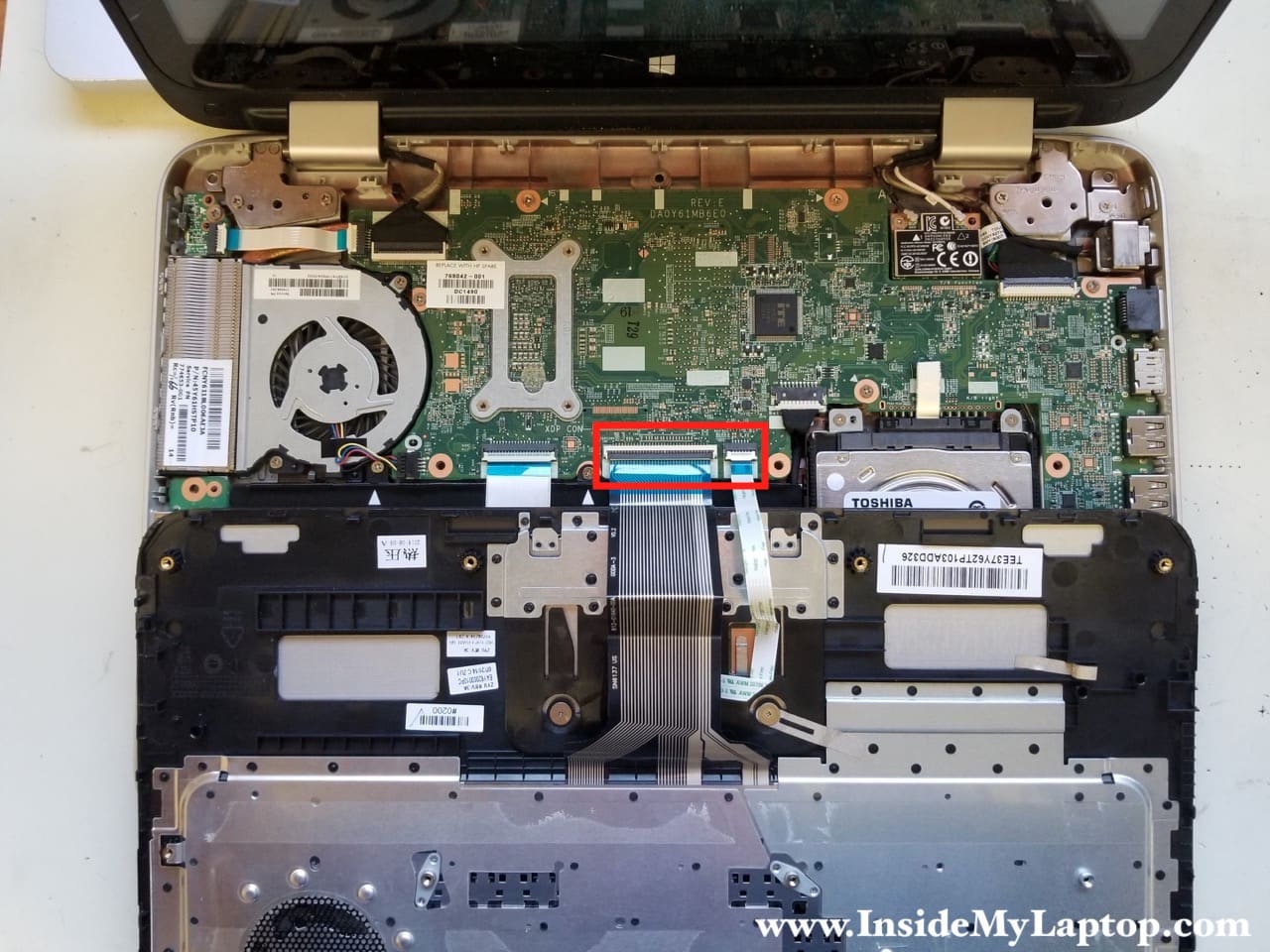
STEP 4.
Both connector has to be unlocked in order to release the cables. It’s done by lifting up the locking tab (red arrows).
Disconnect the keyboard and touchpad cables.

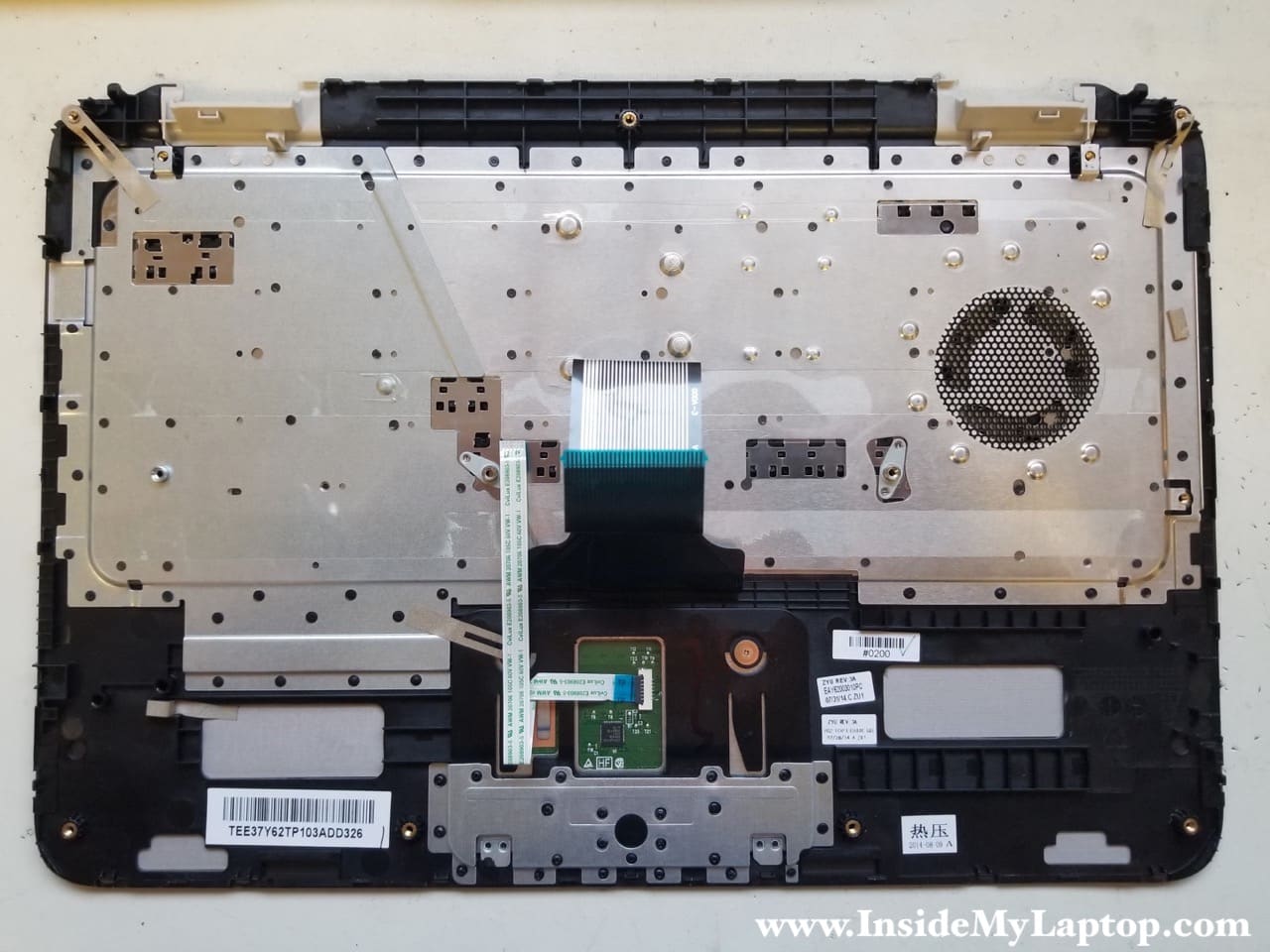
Here’s the palmrest/keyboard assembly removed from the laptop.
You can easily access and replace the touchpad if necessary but the keyboard is riveted to the frame.
If you have a failed keyboard on a HP Pavilion x360 13-a010dx, you will have to replace the entire top case assembly.
STEP 5.
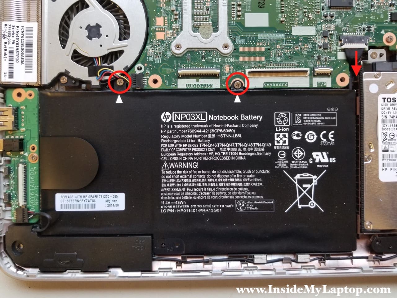
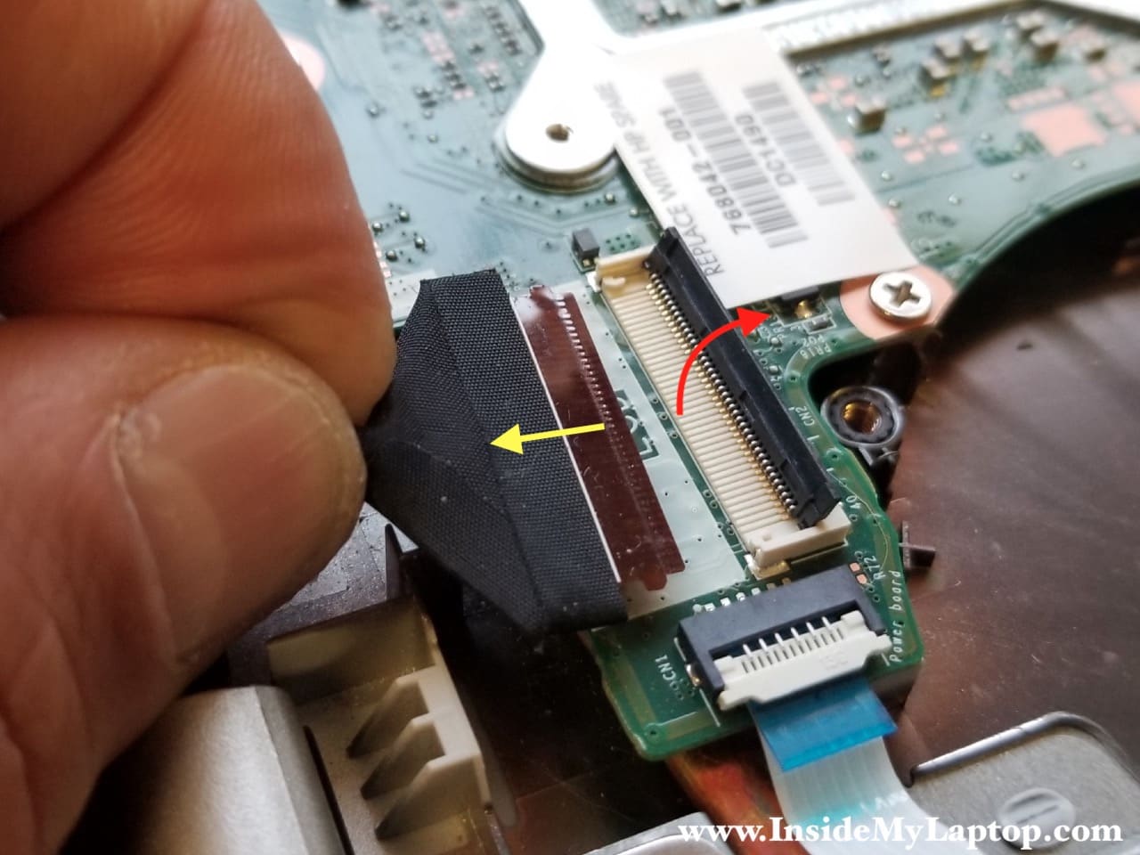
Before removing the battery you’ll have to disconnect and remove the flat cable connecting the motherboard to the USB/audio board.
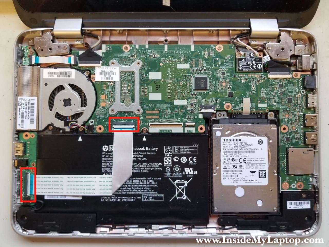
STEP 6.
Remove two screws securing the battery. Disconnect the battery cable from the motherboard.
Replacement battery model NP03XL.
STEP 7.
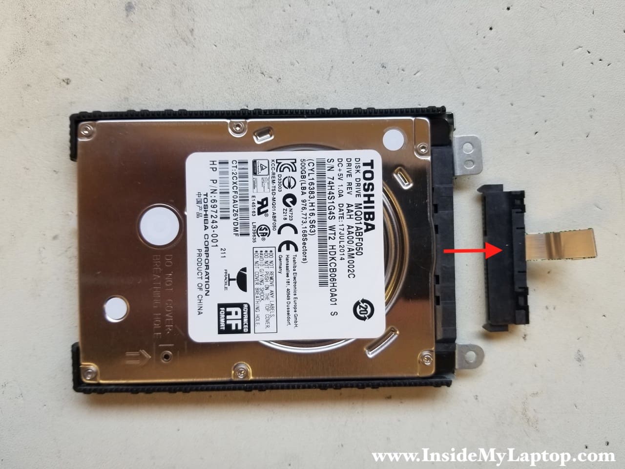
Remove two screws securing the hard drive caddy.
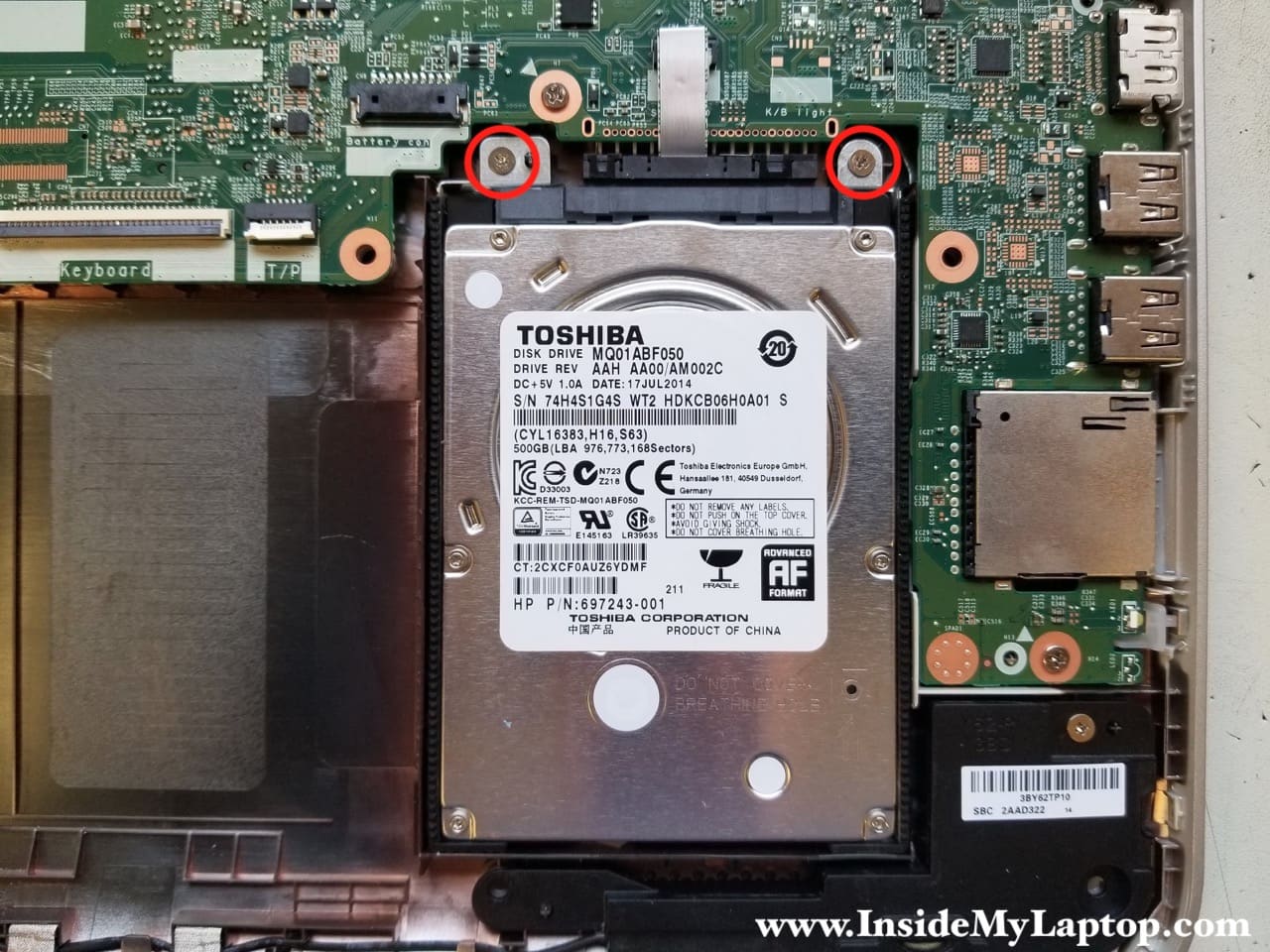
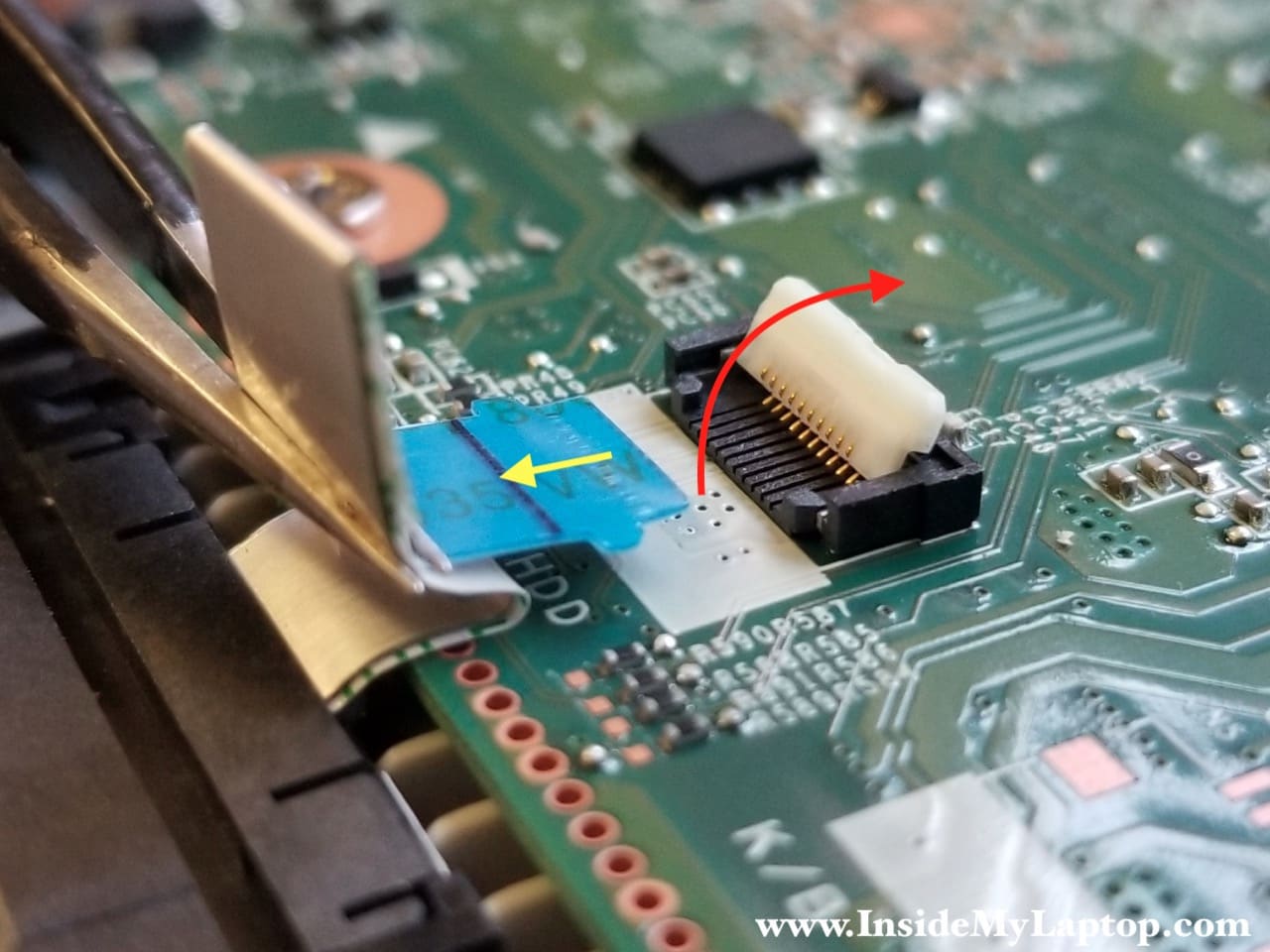
Unlock the hard drive cable connector and release the cable.
Remove the hard drive assembly.
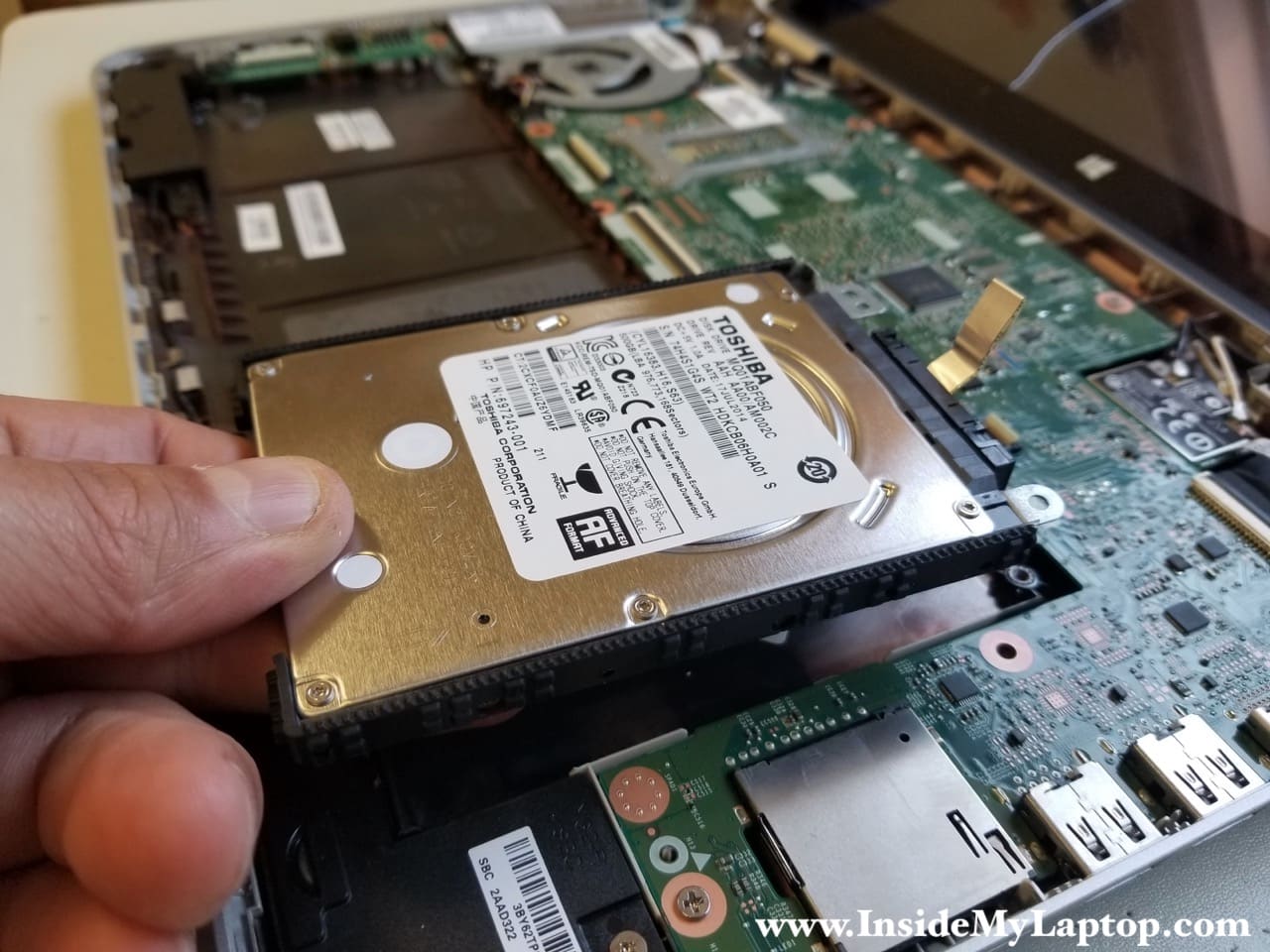
If you are replacing the hard drive or upgrading it to a SSD, you’ll have to transfer the caddy and the cable to the new drive.
Installing a 2.5″ SATA solid state drive instead of the regular hard drive will improve laptop performance significantly.
STEP 8.
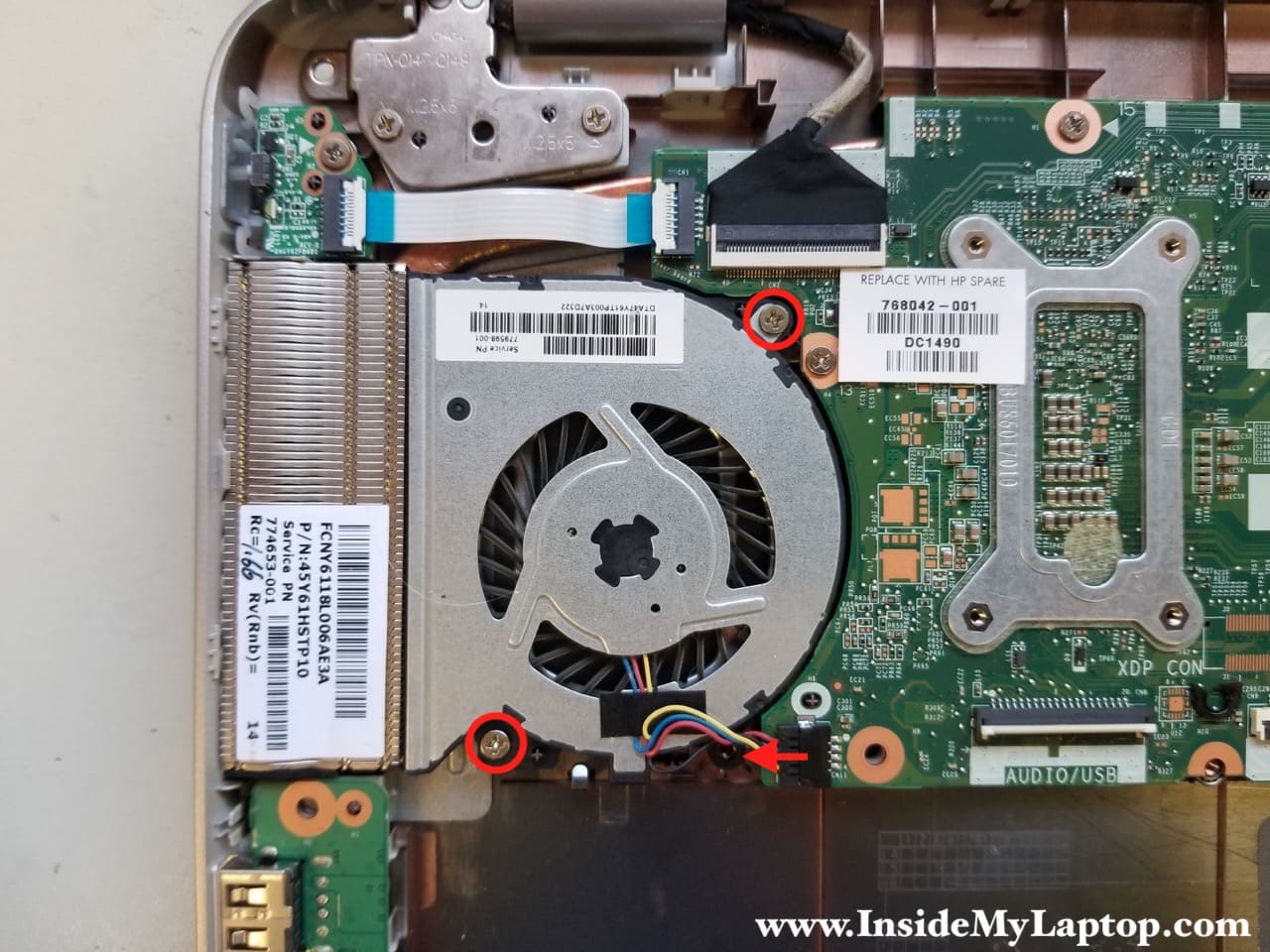
Remove two screws securing the cooling fan. Disconnect the fan cable from the motherboard.
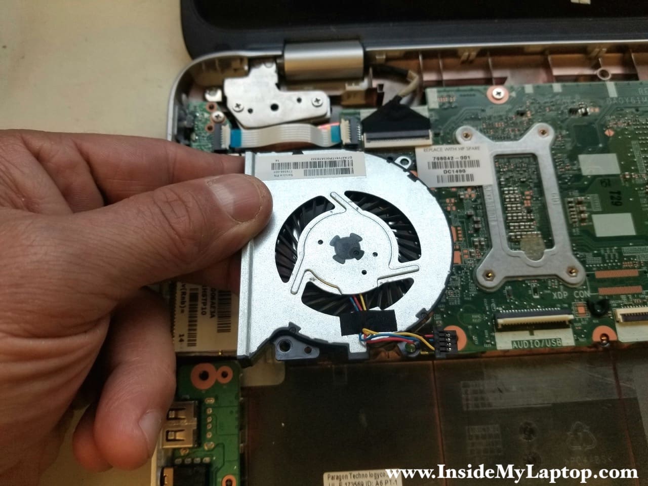
Remove the fan.
STEP 9.
Remove one screw from the USB/audio board.
Unplug the left speaker cable from the board.

Remove the USB/audio board.

STEP 10.
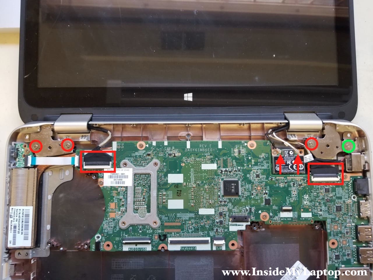
Now we are going to remove the display assembly.
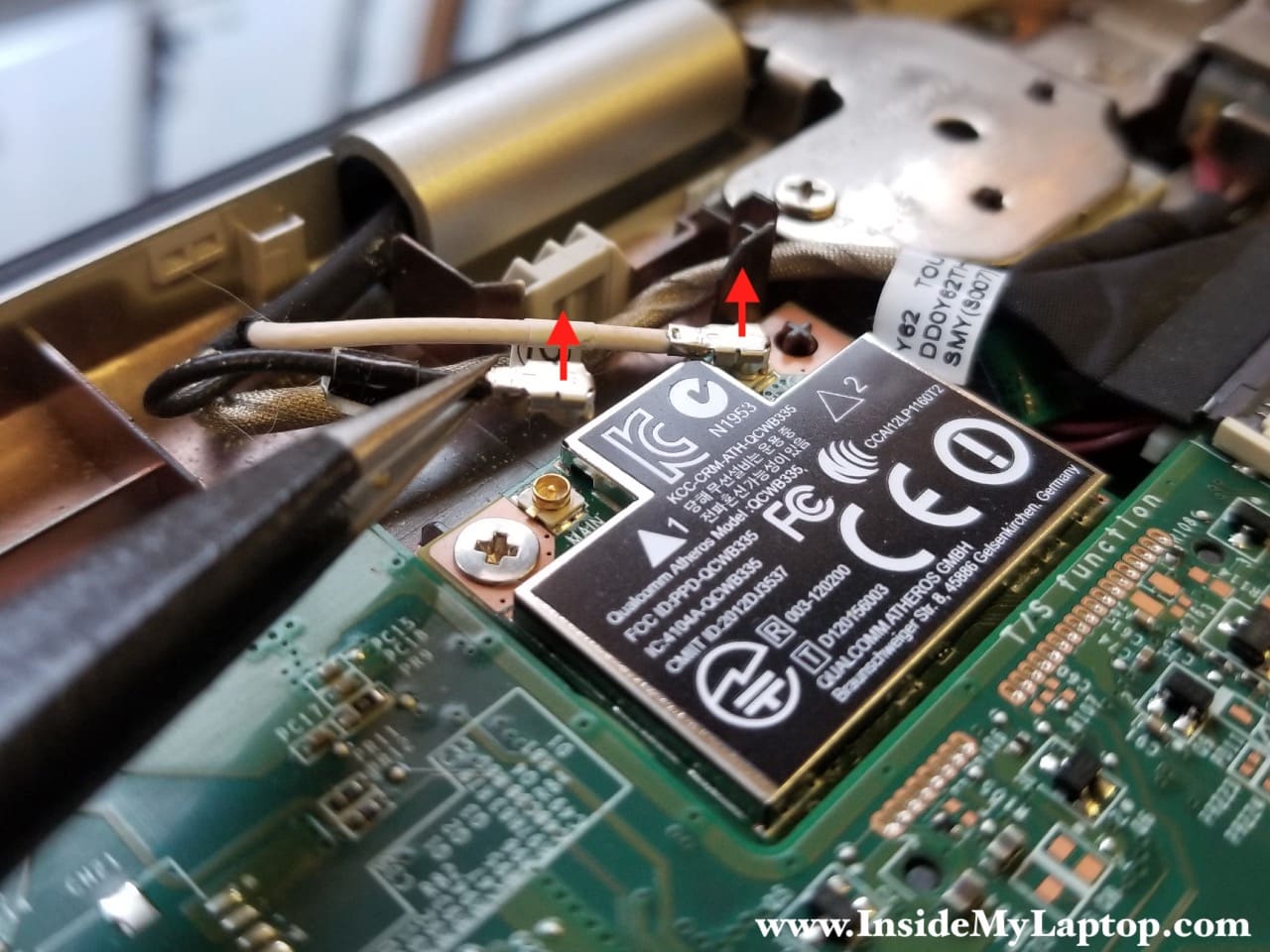
- Disconnect Wi-Fi antennas from the wireless card
- Disconnect both display cables from the motherboard.
- Remove four screws securing display hinges:
NOTE: one of the hinge screws (green circle) is shorten than other three screws. Pay attention during the re-assembly process.
Disconnect both display cables the same way as all other flat cables.
Carefully unsnap the Wi-Fi antennas from the wireless card.
Remove the display assembly.
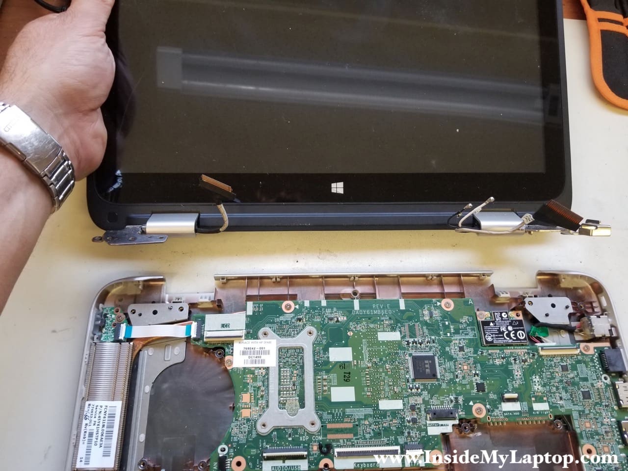
STEP 11.
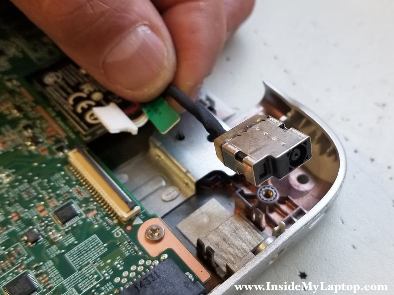
The DC jack can be removed after you remove the display assembly because the jack is mounted under the right hinge.
Unplug the DC jack cable from the motherboard. The connector is located on the bottom side but it’s easily accessible.
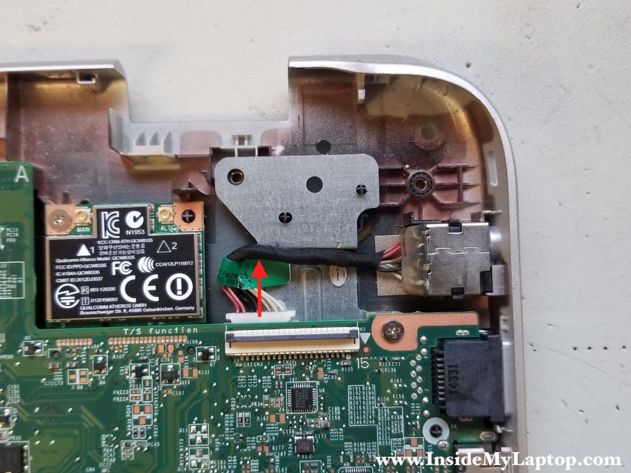
Remove the DC jack.
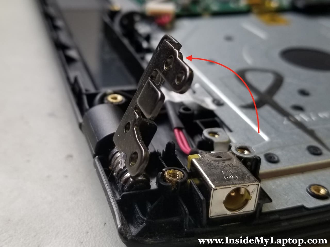
Alternatively, you can remove the DC jack without removing the display. In order to do so you will have to remove the right hinge screws and lift it up as shown on the following picture.
This picture was taken for a different laptop but the idea is the same.
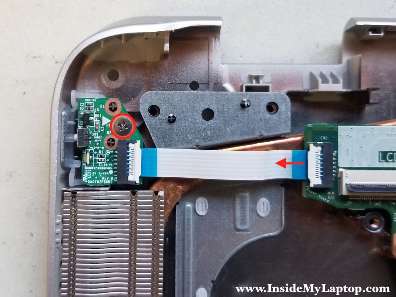
STEP 12.
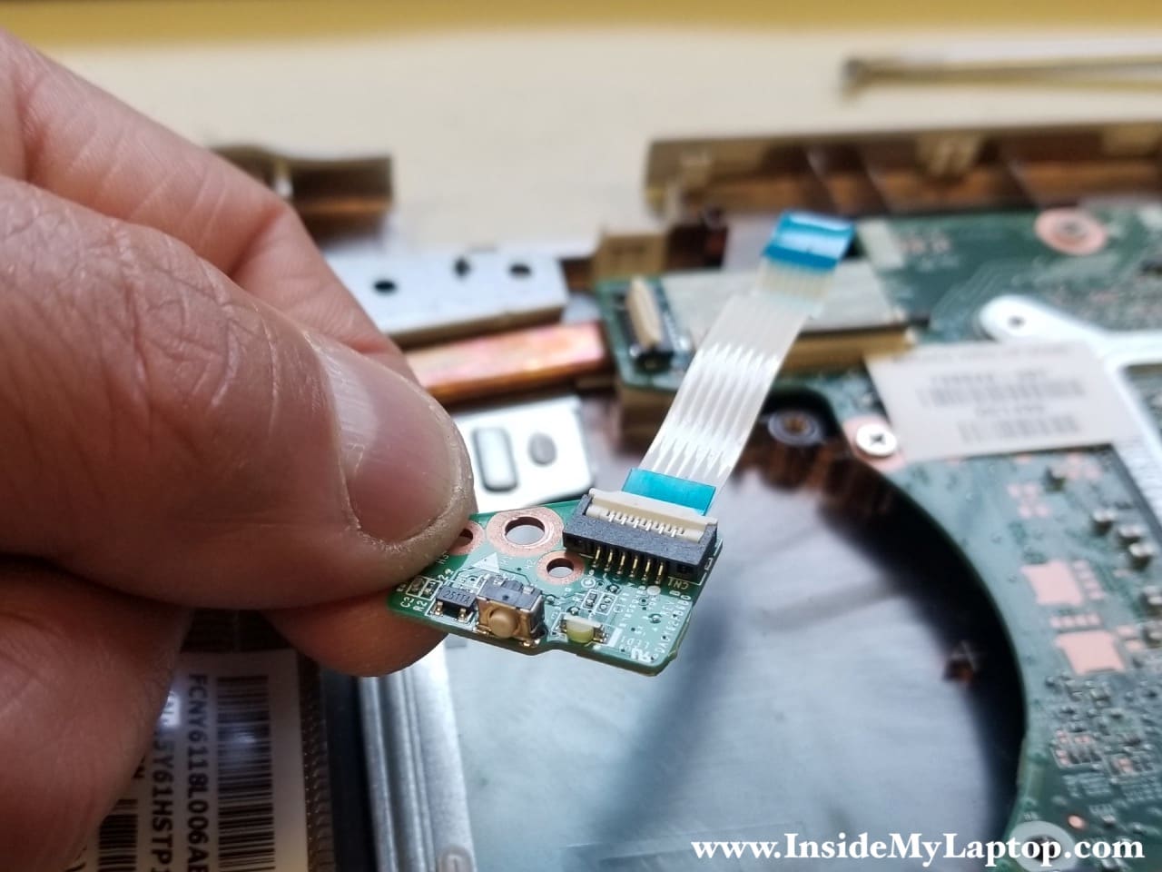
Disconnect the flat cable connecting the power button board to the motherboard. Remove one screw securing the board.
Remove the power button board.
STEP 13.
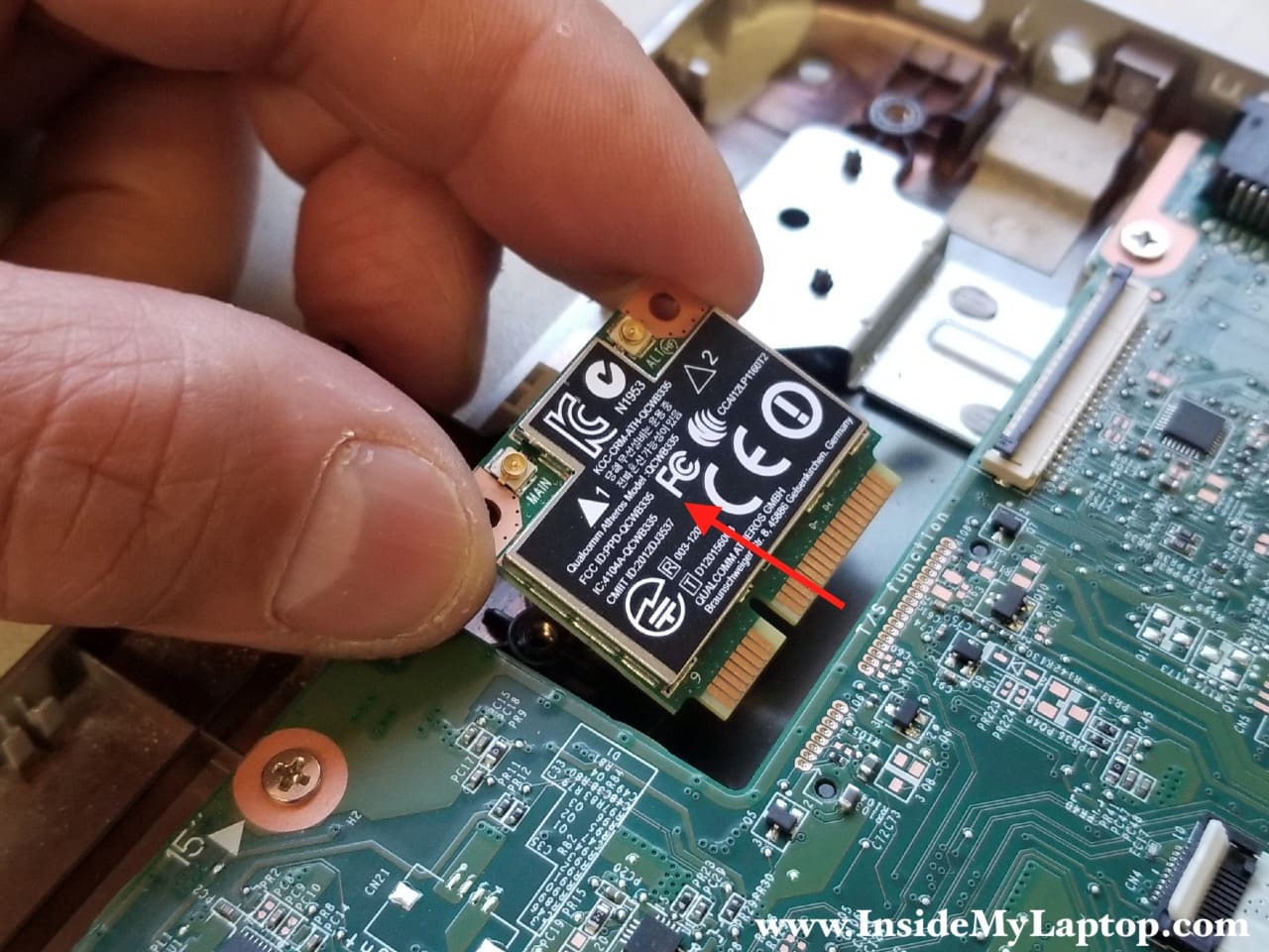
Remove one screw securing the wireless card. The socket is located on the bottom side but it’s easily accessible.
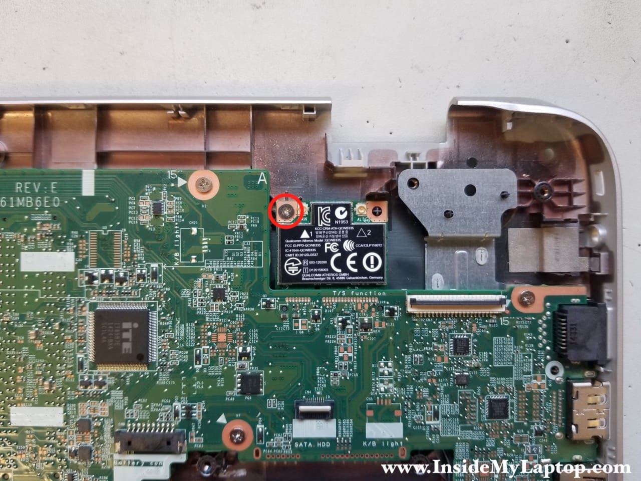
Pull the wireless card out.
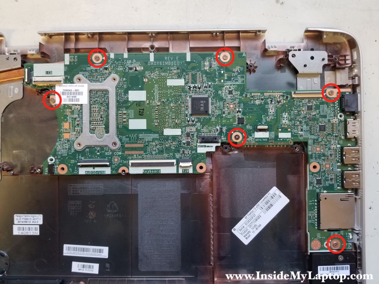
STEP 14.
Remove all screws securing the motherboard.
STEP 15.
Lift up the left side of the motherboard and remove it from the bottom case.
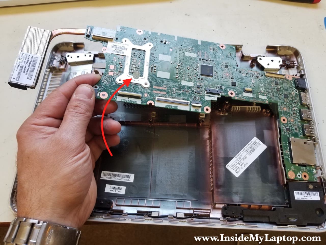
As I mentioned earlier, in HP Pavilion x360 13-a010dx laptop both memory slots are hidden on the bottom of the motherboard.
So it will take some effort to upgrade memory.
This laptop can handle up to 16GB (2x8GB) DDR3-12800 SODIMM RAM modules.

Here’s a picture of the bottom case with everything removed. Both speakers are still attached to the case.

Emma
Very helpful and easy steps to understand.
Silvia Carolina Bohorquez
Can you tell me which is the graphic chip on the motherboard?
Best Regards