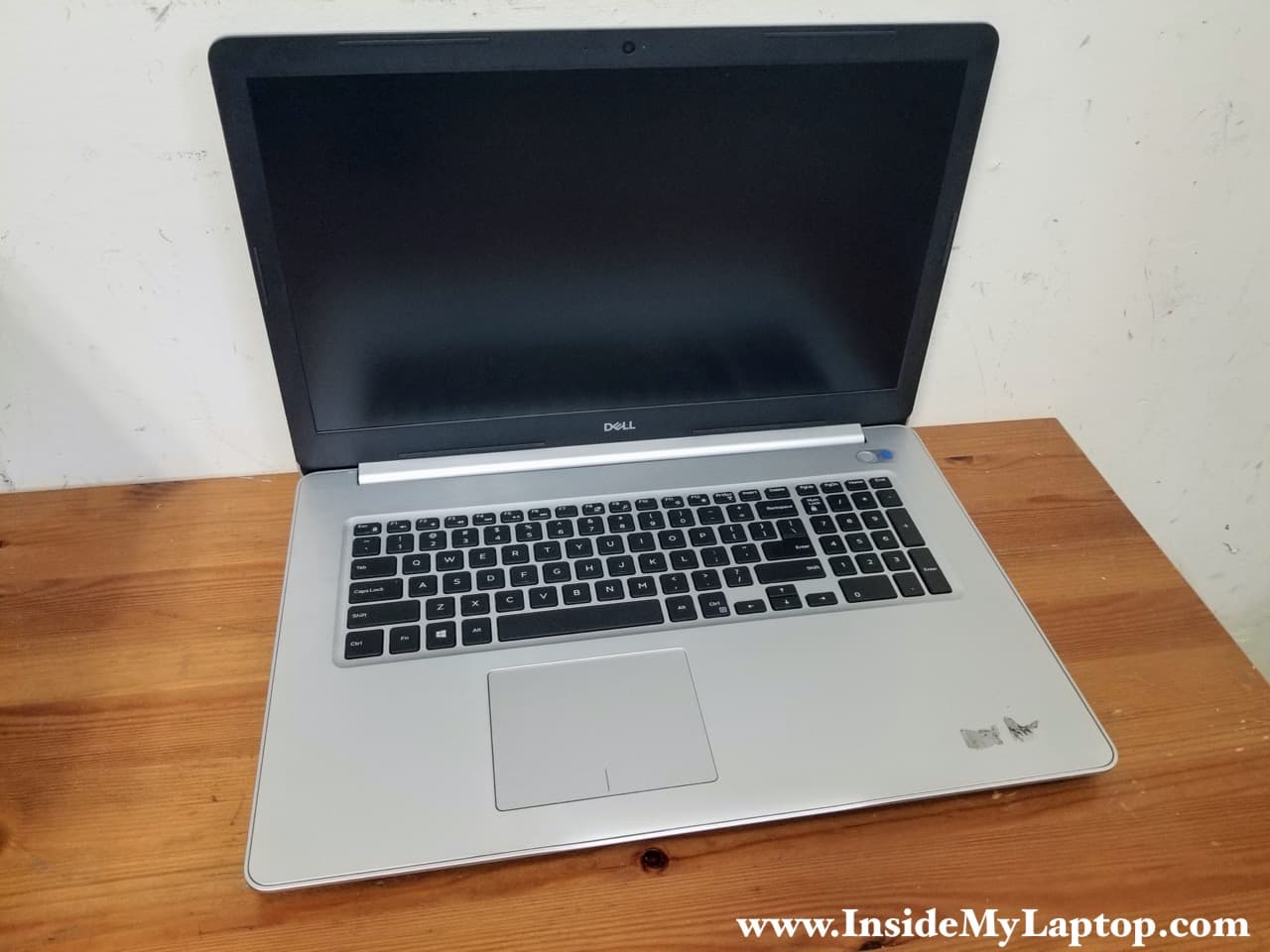
In this guide I’ll be taking apart Dell Inspiron 17 5770 5775 (model P35E) laptop. It’s possible this guide will work for some other models in the Dell Inspiron 17 5000 series computer line.
For this disassembly you will need only two basic tools: Phillips #1 and #0 screwdrivers. Needle tweezers are optional but very helpful for disconnecting internal cables.
Removing base cover
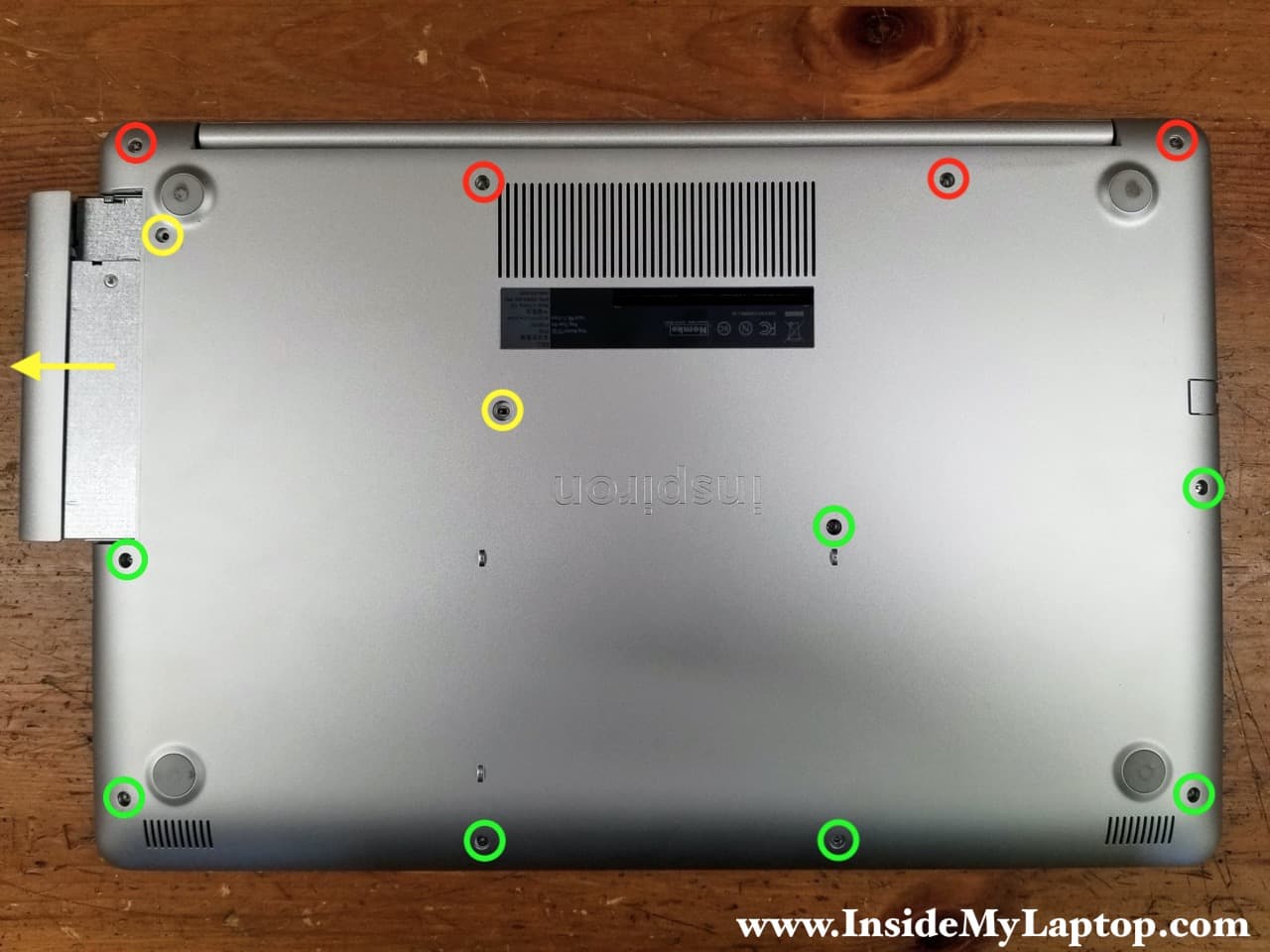
STEP 1.
Loosen four captive screws (color-coded in red) securing the base cover. The captive screws will stay attached to the base cover when it’s removed. Remove nine more screws (yellow and green).
Carefully pull the optical drive out.
STEP 2.
Remove two more screws located in the optical drive bay.

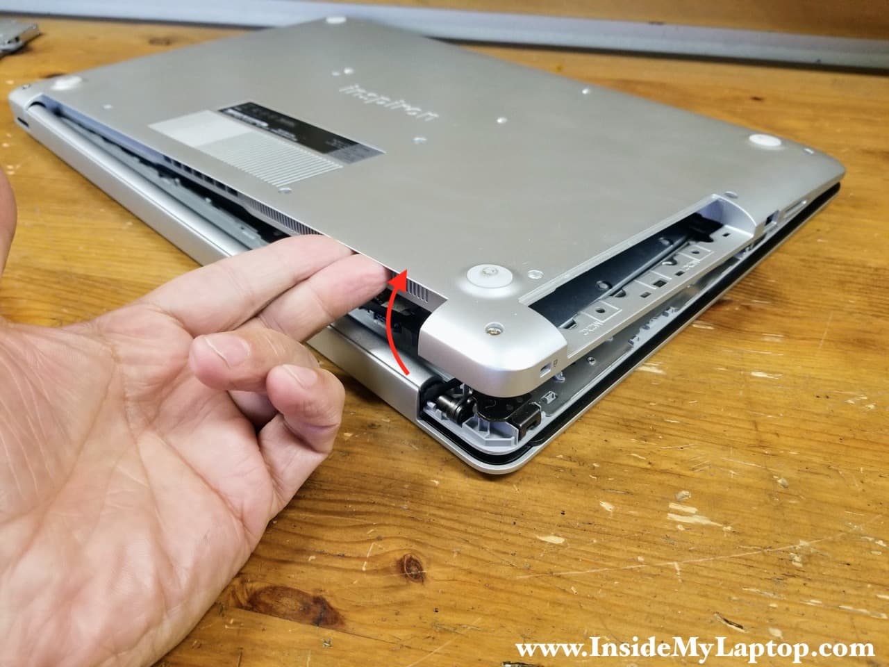
STEP 3.
Start separating the base cover from the top case assembly. Start removing the base cover around the display hinge area.
STEP 4.
Remove the base cover.

Removing battery
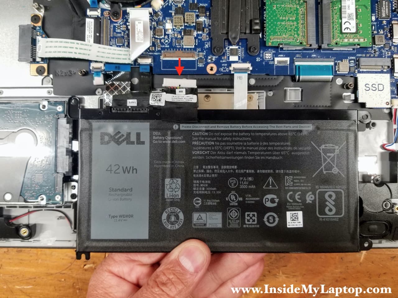
STEP 5.
Remove four screws attaching the battery to the top case.

STEP 6.
Lift up the battery and disconnect the battery cable from the motherboard. Remove the battery.
Dell Inspiron 17 5770 5775 (model P35E) battery type: WDX0R.
Dell part number: 0CYMGM.
Removing memory and hard drive
Dell Inspiron 17 5770 5775 (model P35E) has two memory slots. This laptop can take up to 32GB (2x16GB) DDR4 -2400 RAM modules.

STEP 7.
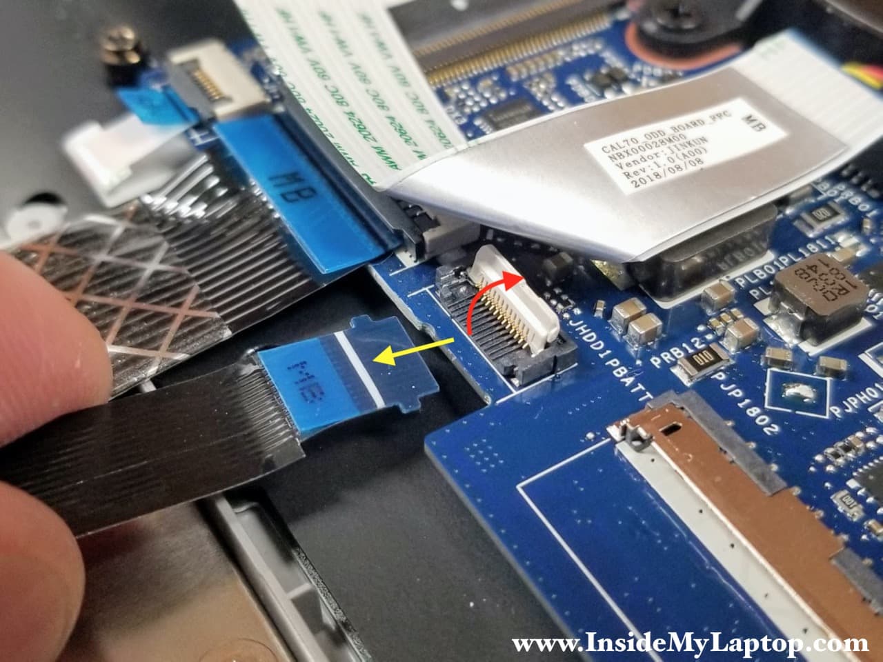
Remove four screws securing the hard drive caddy and disconnect the SATA cable from the motherboard.

Here’s how to disconnect the SATA cable from the motherboard.
Lift up the white locking tab to unlock the connector (red arrow). Lift up and pull the cable out (yellow arrow).
If you are upgrading to a 2.5″ SSD it’s necessary to move the bracket and the SATA cable to the new drive.

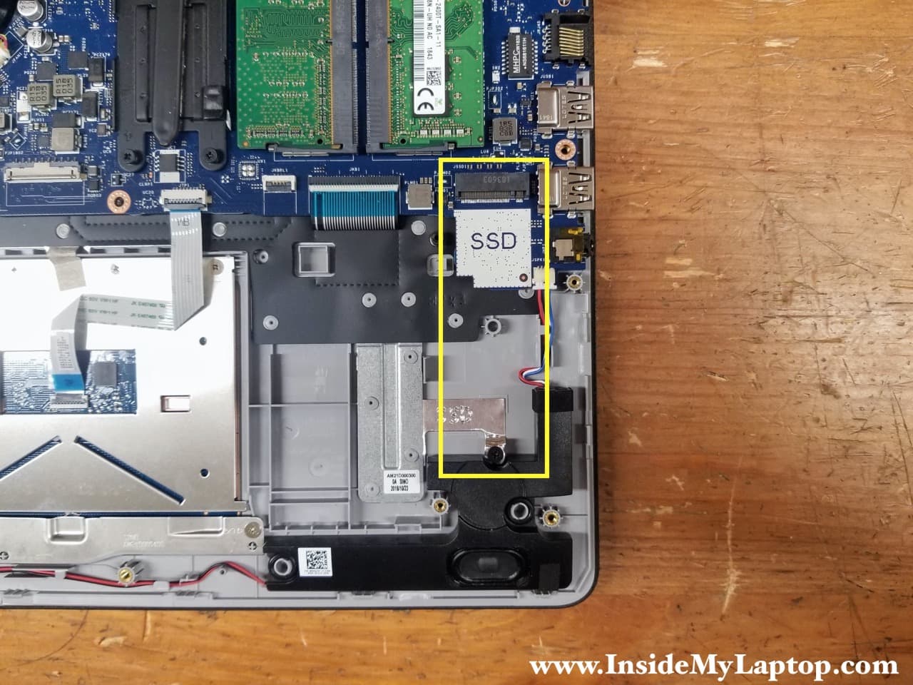
Dell Inspiron 17 5770 5775 (model P35E) has a PCIe M.2 slot where you can install a PCIe NVMe M.2 solid state drive. In this particular case the SSD mounting screw located in the further hole which is for a 2280 type SSD.
If your laptop didn’t come with a PCIe M.2 drive I would recommend installing it.
Removing cooling fan
STEP 8.
Remove three screws securing the cooling fan and disconnect the fan cable from the motherboard.
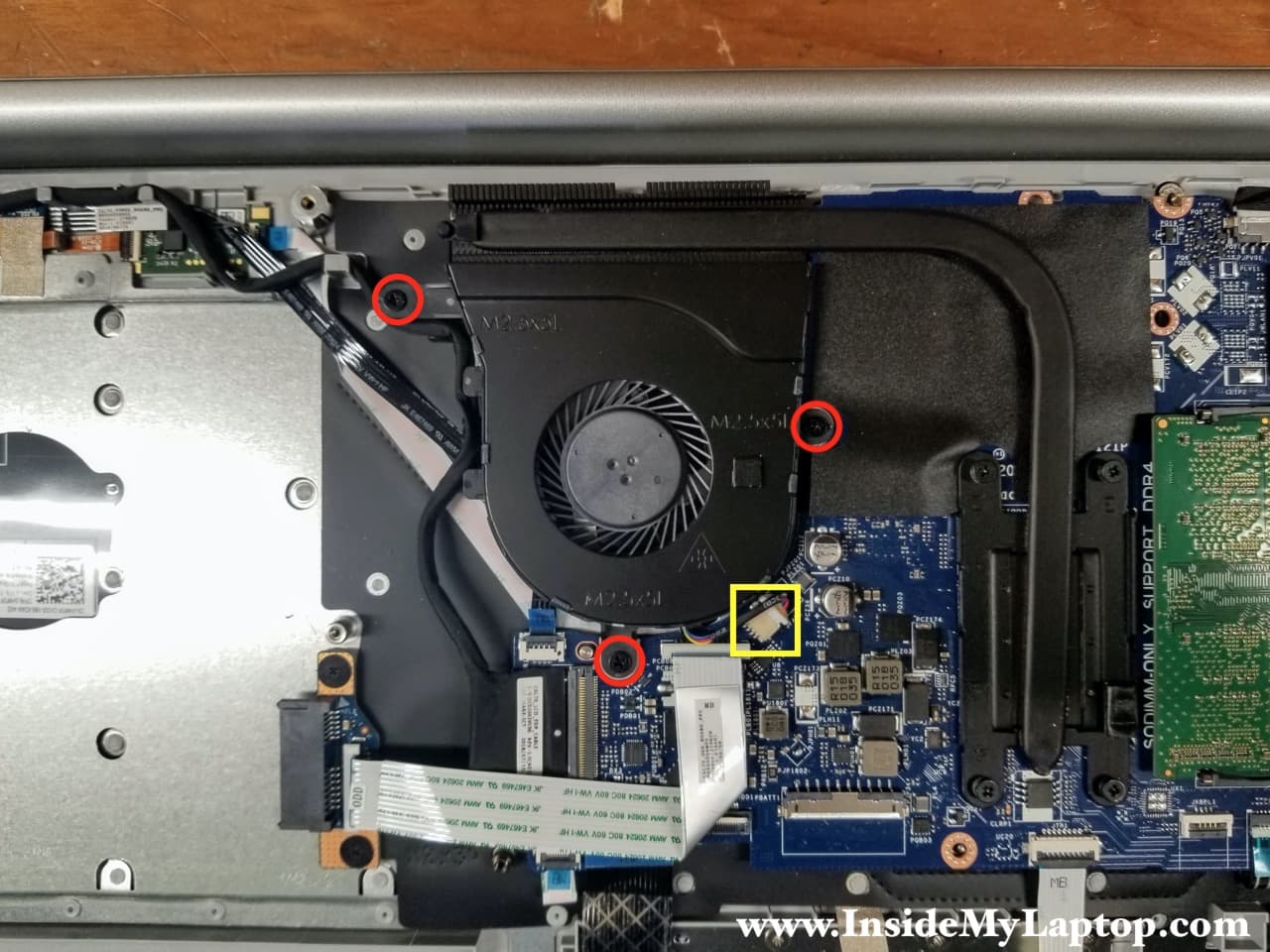
STEP 9.
Lift up the fan and un-route the display cable from the guided path on the left side of the fan.

STEP 10.
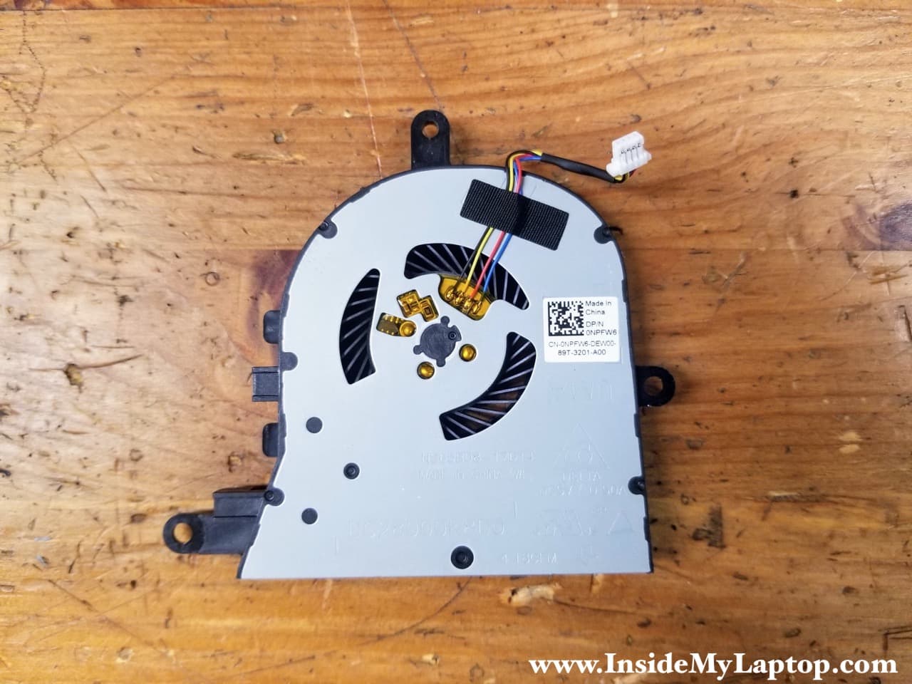
Remove the cooling fan.
Dell Inspiron 17 5770 5775 (model P35E) fan part number: 0NPFW6.
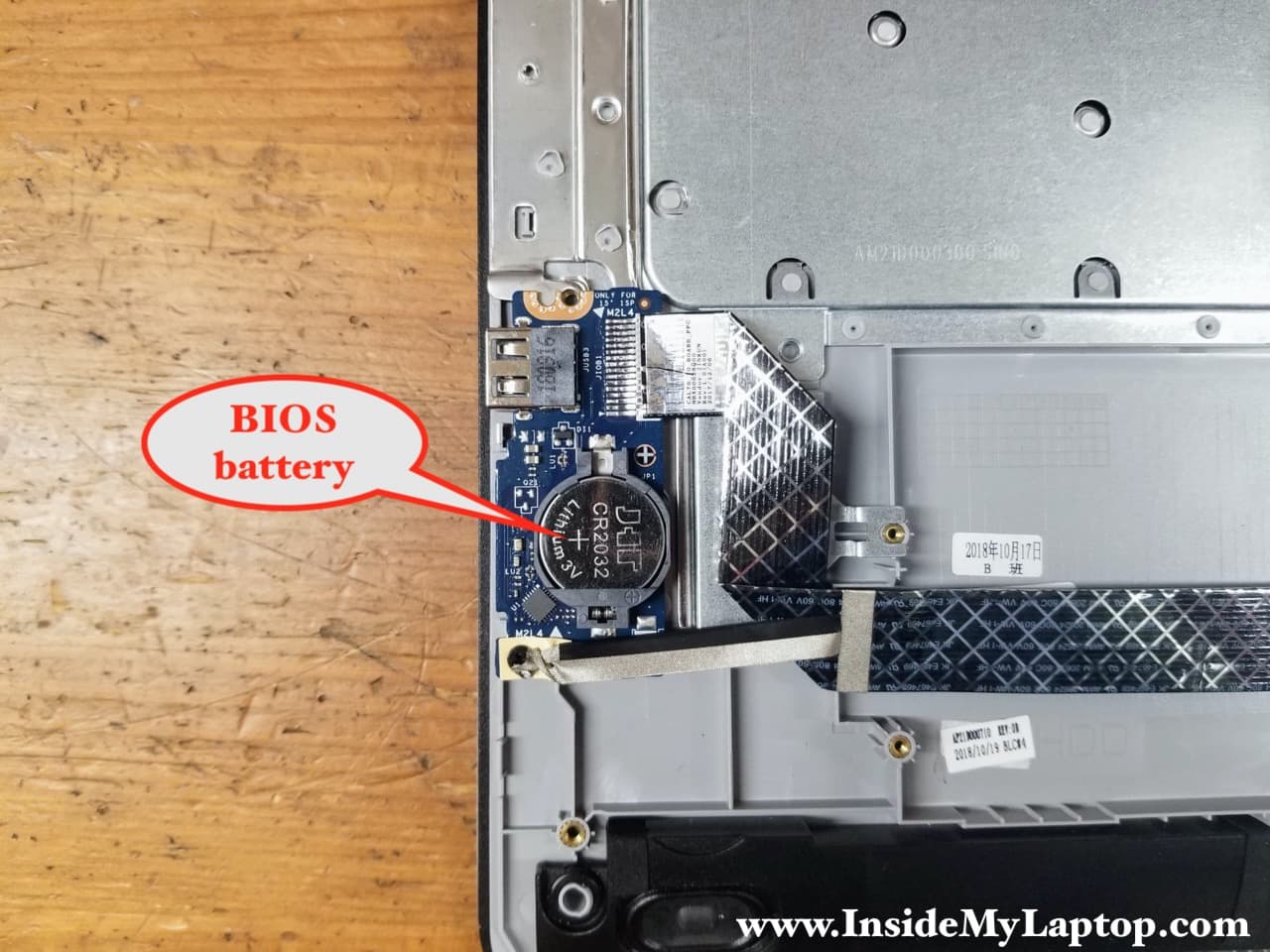
The BIOS battery located on the I/O board (USB Card reader board). This board can be easily removed.
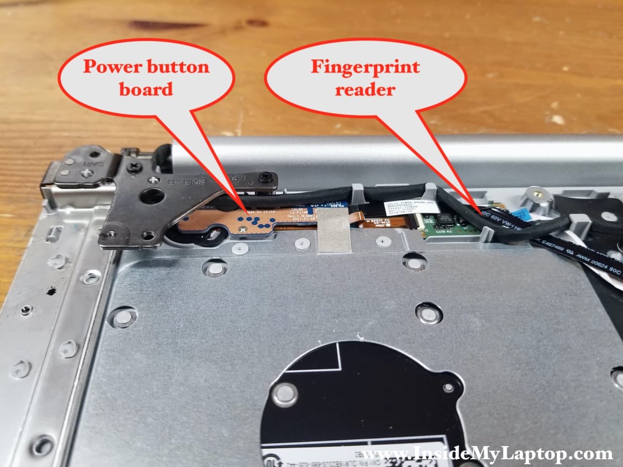
The power button and the fingerprint reader also located on the separate boards.
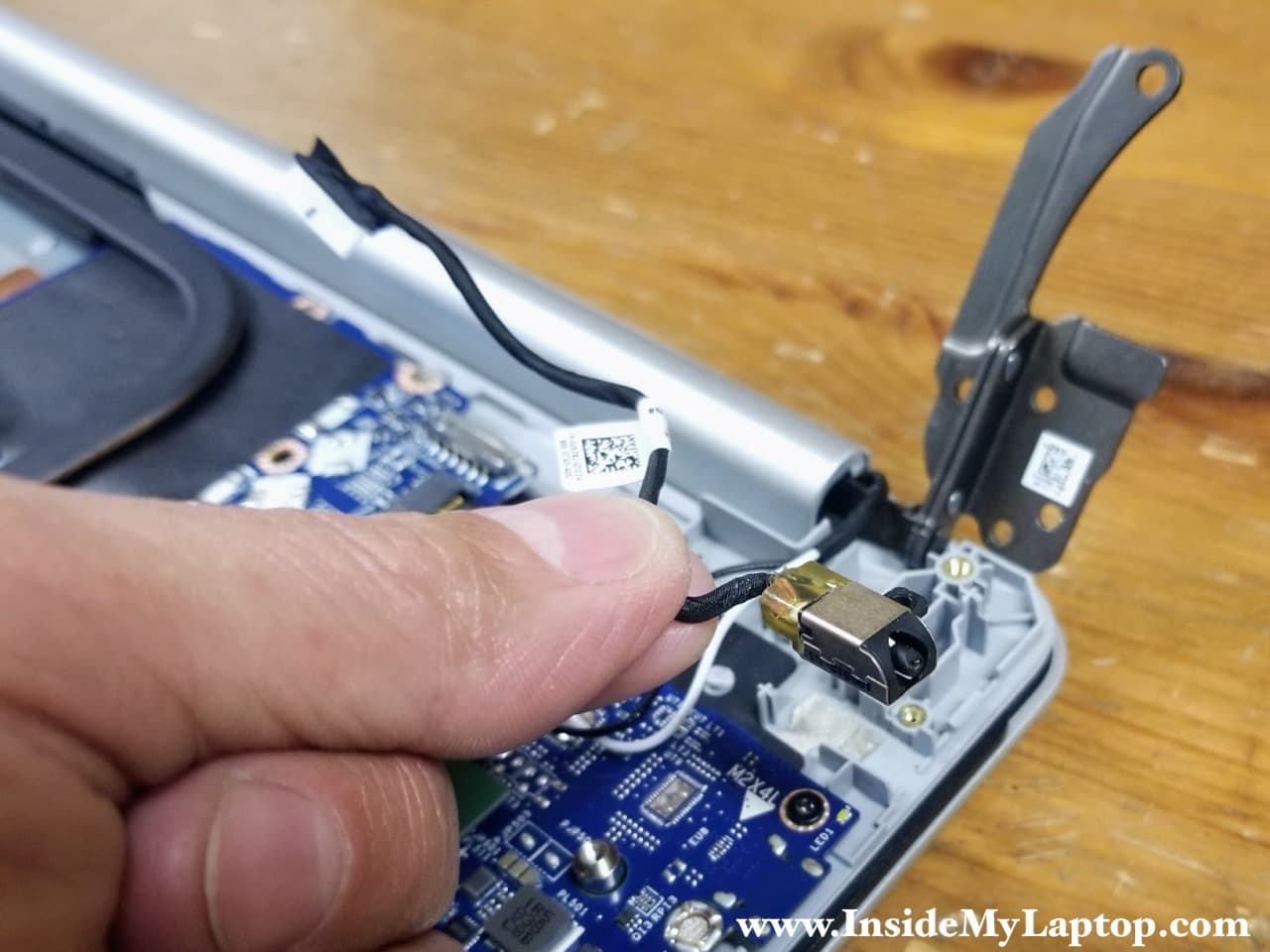
Removing DC power jack
The DC power jack is mounted under the left display hinge which has to be lifted up in order to access the DC jack.
STEP 11.
Remove three screws securing the right display hinge.

STEP 12.
Lift up the display hinge as it shown on the following picture.

STEP 13.
Disconnect one screw securing the DC jack and unplug the DC jack cable from the motherboard.

STEP 14.
Lift up and remove the DC jack harness.
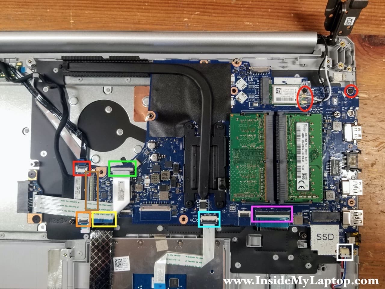
Removing motherboard
With the left display hinge lifted up you can disconnect and remove the motherboard now.
Remove one screw securing the motherboard.
Disconnect the following color-coded cables:
– Fingerprint scanner cable (red).
– Display cable (brown).
– Power button board cable(orange).
– I/O board cable (yellow).
– Optical drive connector board cable (green).
– Touchpad cable (blue).
– Keyboard cable (pink).
– Speaker cable (white).
After all cables are disconnected you can lift up the motherboard and remove it.
JAMES R ABT SR
you’ve made my life so much easlier with this photo tear down. Thank so very much.
Jim, stay safe and well….