
In this guide I show how to disassemble an HP Spectre x360 15-ch series Convertible PC .
This guide will work for many different models of HP Spectre x360 15 Convertible PCs (model numbers 15-ch000 through 15-ch099):
15-ch000na, 15-ch002tx, 15-ch003tx, 15-ch004na, 15-ch005na, 15-ch008ca, 15-ch008tx
15-ch011dx, 15-ch011nr, 15-ch012nr, 15-ch015nd, 15-ch015nr, 15-ch017nr
15-ch012nr, 15-ch012nf, 15-ch012tx, 15-ch013tx, 15-ch020nd, 15-ch025nd
15-ch031ng, 15-ch032ng, 15-ch034ng, 15-ch040nz, 15-ch050na, 15-ch050nz, 15-ch054na
15-ch055na, 15-ch060nz, 15-ch070nz, 15-ch075nr, 15-ch090na, 15-ch099na
For this disassembly I will be using the following repair tools: Torx T5 screwdriver, Phillips #1 screwdriver, case opener tool, fine tweezers.
Base cover removal
STEP 1.
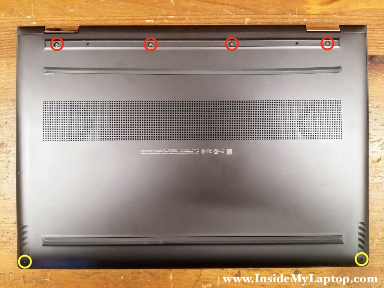
Remove six screws from the base cover.
Four silver screws (red) are hidden under the self-adhesive rear bottom foot. Peel off the foot to access the screws.
STEP 2.
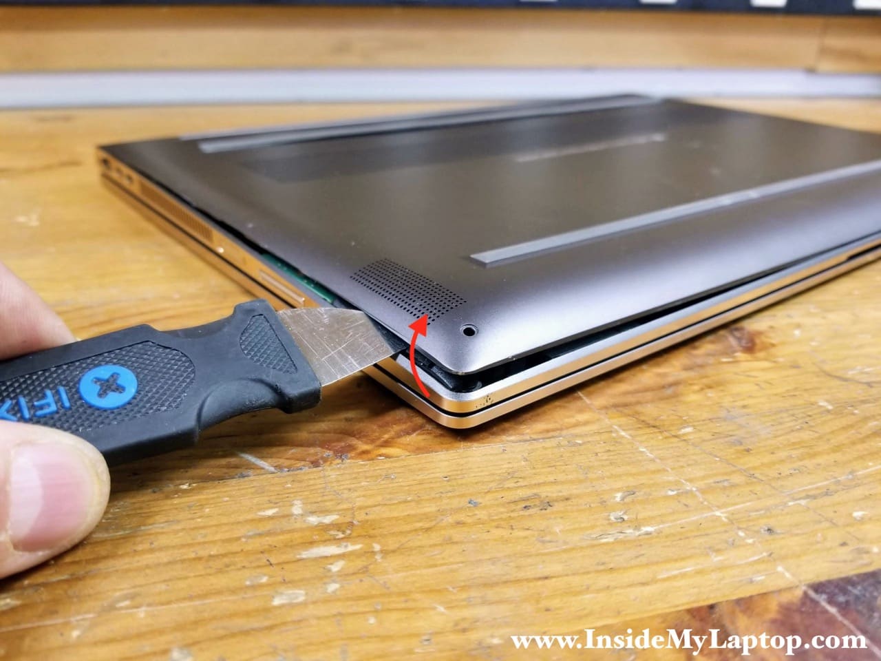
Insert the case opener tool between the base cover and the top case assembly. Pry up the base cover to start separating it from the top case. Continue removing the base cover with your hands while helping yourself with the case opener tool. The base cover is fitted very tightly and it might be necessary to apply some reasonable force to remove it.
STEP 3.
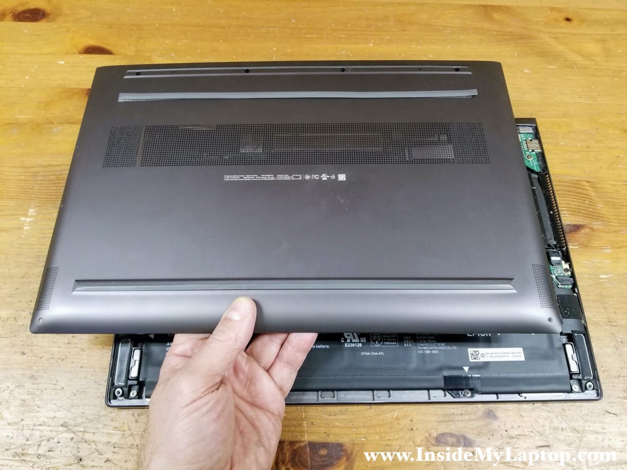
Remove the base cover completely.
Battery removal
STEP 4.
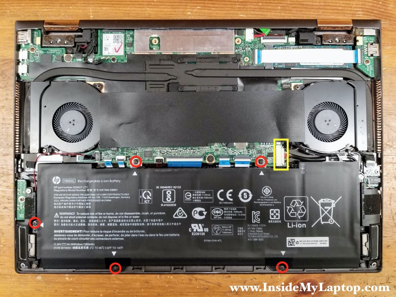
Remove five screws attaching the battery to the top case assembly.
STEP 5.
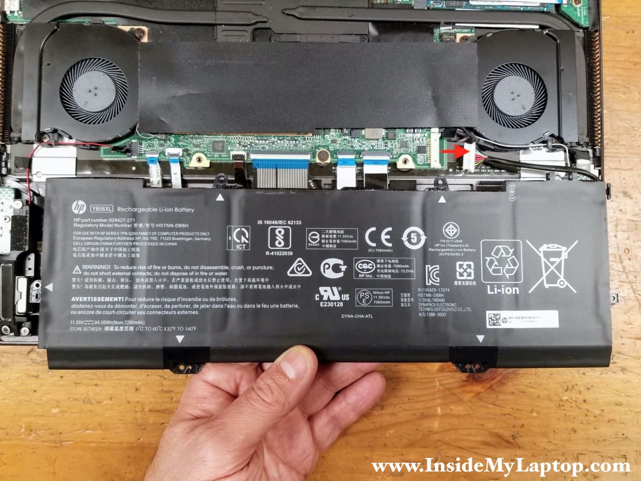
Lift up the battery and disconnect the battery cable from the motherboard.
HP Spectre x360 15-ch series battery type: YB06XL. HP spare part number: 928372-855.
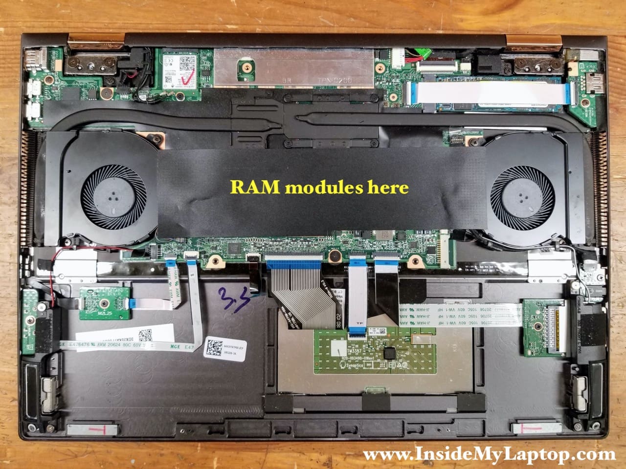
RAM modules removal
Both memory (RAM) modules are located under the black mylar sheet. According to Crucial website HP Spectre x360 15-ch can handle 16GB (2x8GB) DDR4-2400 SODIMM modules. I looked at other sources and I think upgrading it to 32GB (2x16GB) shouldn’t be a problem.
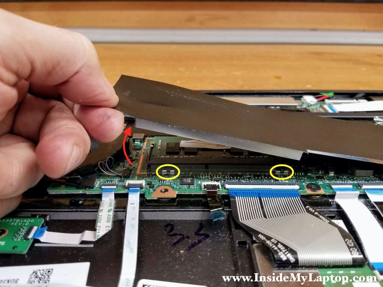
STEP 6.
There is a metal RAM cover under the mylar sheet which is attached to the sheet with adhesive. Carefully pull the mylar sheet up to separate the metal cover from the clamps (yellow ovals) on the motherboard.
Here’s the other side of the RAM cover.

STEP 7.
Now you can access both memory slots on the motherboard and replace or upgrade RAM modules if necessary.

Cooling fans removal
STEP 8.
Remove two screws securing the left cooling fan and disconnect the fan cable from the motherboard.

Here’s how to disconnect the fan cable. Grab the cables as close to the connector as possible using needle-nose tweeters and lift it up. The cooling fan cable connector plugs/unplugs vertically.

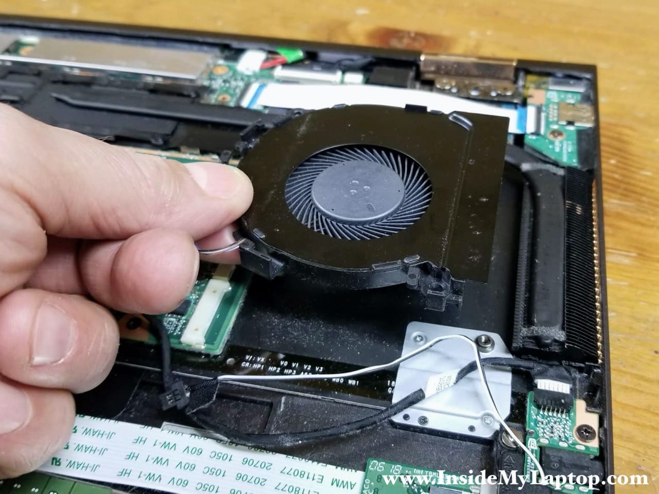
STEP 9.
Lift up and remove the left fan. While removing the fan you’ll have to un-route the left front speaker cable from the guided path on the side of the fan.

STEP 10.
Disconnect the audio board cable (red) and the right front speaker cable (yellow) from the motherboard. Un-route both cables from the guided path on the side of the fan.

STEP 11.
Remove two screws and disconnect the fan cable from the motherboard.

STEP 12.
Lift up and remove the right cooling fan.
Power button board removal
STEP 13.
Remove one screw securing the USB power button board and disconnect the I/O cable from the motherboard.

Here’s how to disconnect the I/O cable. Lift up the locking tab securing the cable inside the connector (red arrow) and pull the cable out.

STEP 14.
Lift up and remove the USB power button board with the I/O cable attached.

PCIe M.2 SSD removal
STEP 15.
Remove one screw securing the PCIe NVMe M.2 solid state drive.

STEP 16.
Pul the solid state drive out.

You will find a few small boards attached to the top case assembly:
– Volume button board.
– Fingerprint scanner board.
– Memory card reader board.
– Headphones jack board (called audio board in the service manual).
I don’t show how to remove them but it shouldn’t be difficult. All these boards are secured by one screw and can be easily removed.

Motherboard removal
STEP 17.
Carefully disconnect both antenna cables from the wireless card.

STEP 18.
Disconnect the left rear speaker cable (yellow) and the webcam cable (green) from the motherboard.

STEP 19.
Disconnect the DC power jack cable (red), the display panel cable (green) and the right rear speaker cable (green) from the motherboard.

The display panel cable is located very close to the laptop case and you’ll have very limited space to work.
Here’s how to disconnect the display cable. Lift up the locking tab securing the cable inside the connector (red arrow). Lift up and remove the display cable from the connector.

STEP 20.
Disconnect the following color coded cables from the motherboard:
– Left front speaker cable (red).
– Fingerprint reader cable (orange).
– Volume button board cable (yellow).
– Keyboard backlight cable (green).
– Keyboard cable (blue).
– Touchpad cable (pink).
– Memory card reader cable (white).

Don’t forget to unlock all connector before removing the cables.

STEP 21.
Remove three screws attaching the motherboard to the top case assembly.
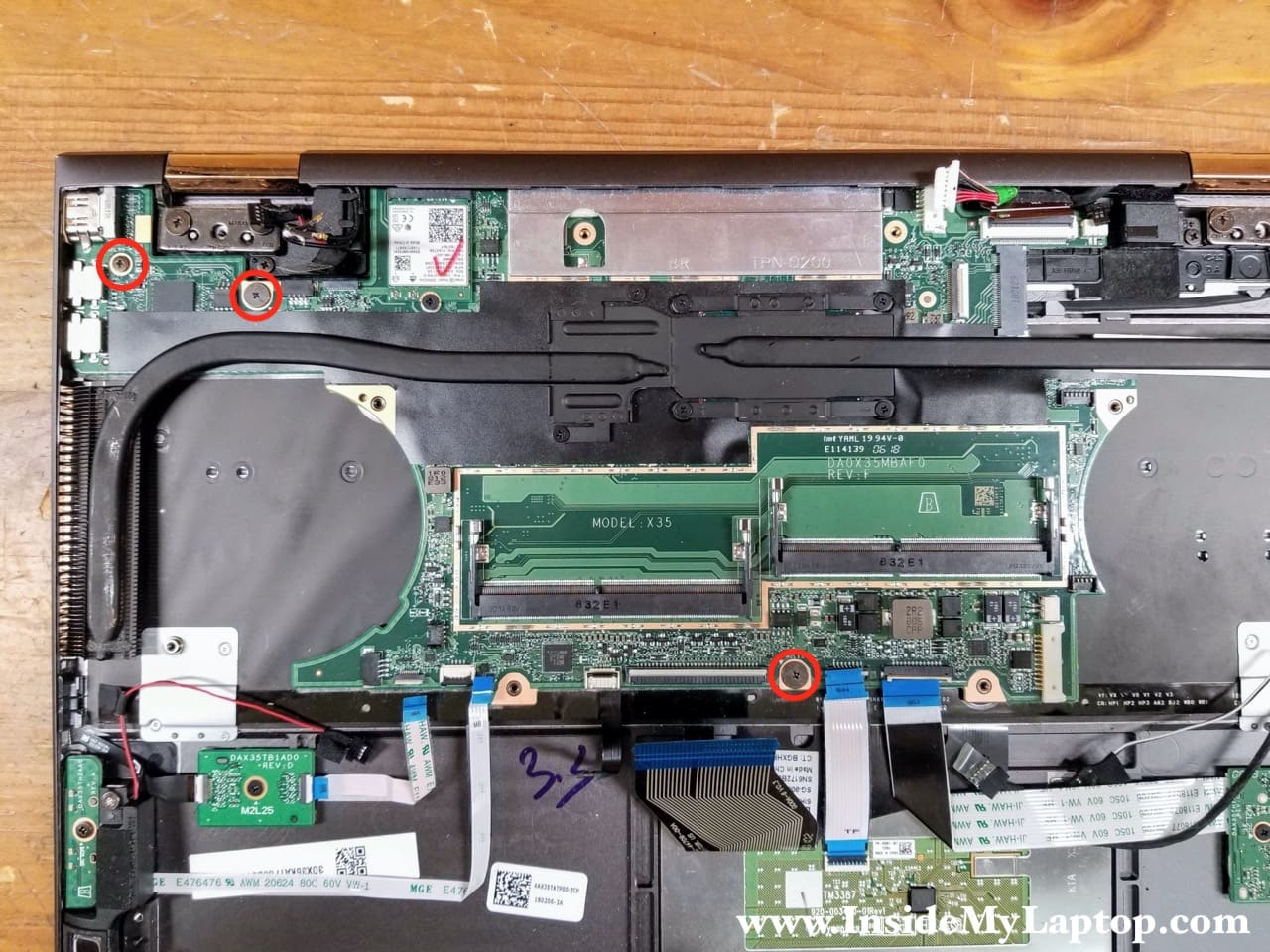
STEP 22.
Separate the motherboard from the top case assembly.
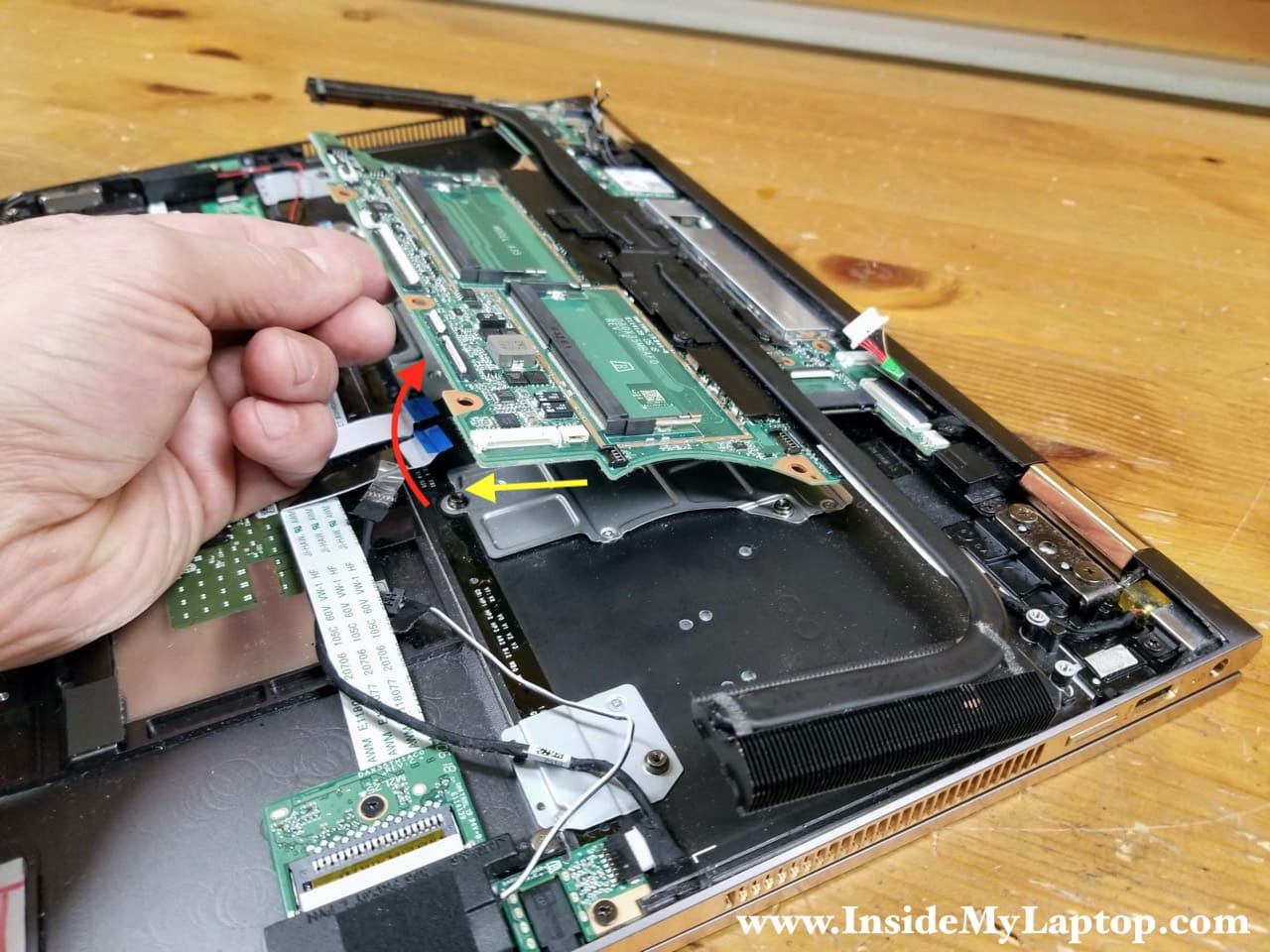
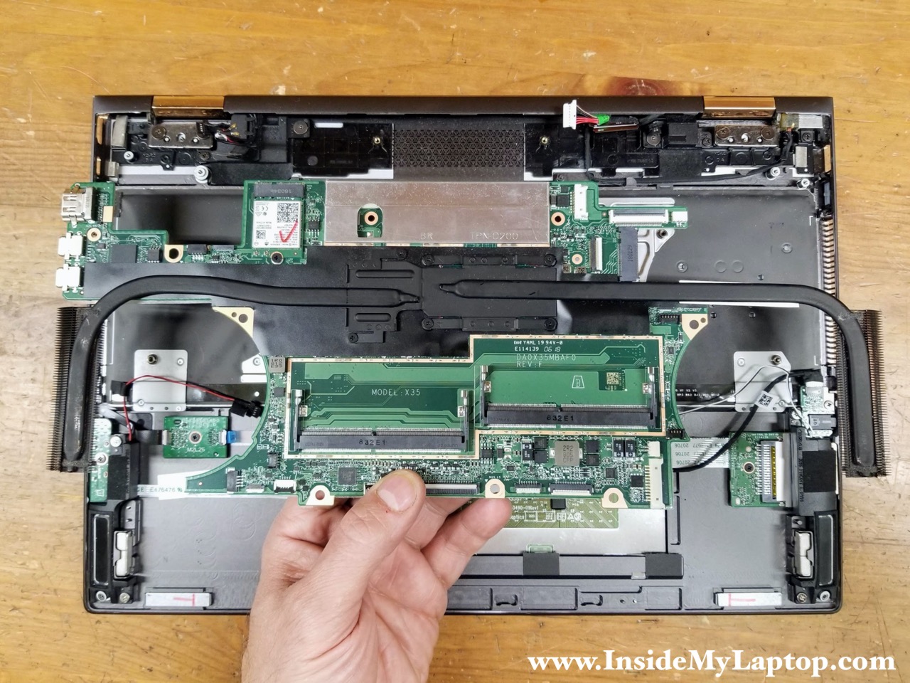
STEP 23.
Remove the motherboard.
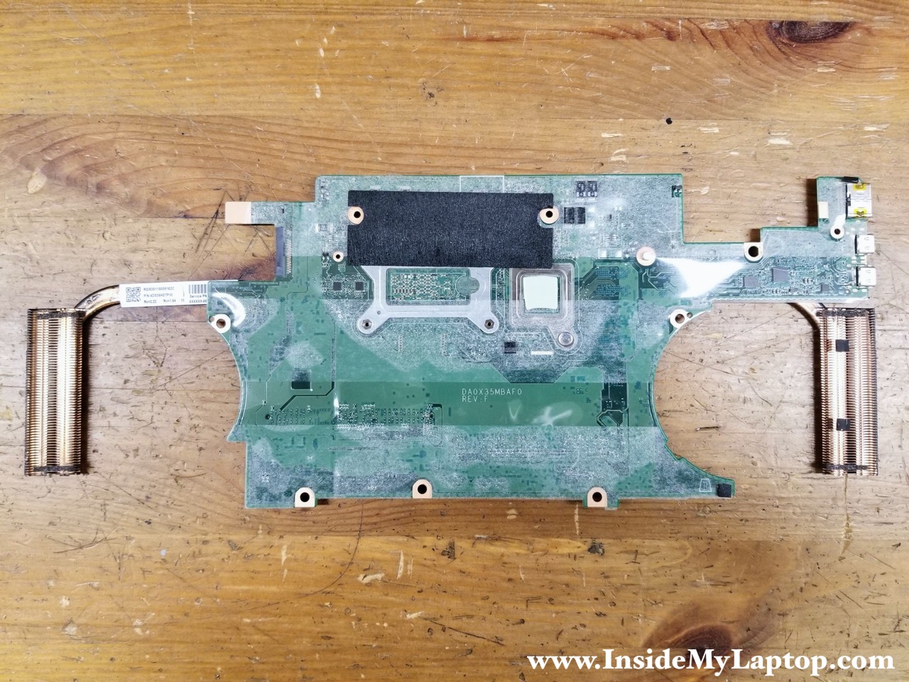
Here’s the other side of the motherboard.
DC-IN power jack removal
STEP 24.
Remove one screw securing the DC-IN power jack and pull the DC jack cable from the case

STEP 25.
Remove the DC-IN power jack.

Display removal
STEP 26.
Open the display panel 270 degrees and remove four screws securing the display panel hinges.
Un-route the speaker cable and the webcam cable from the left side.
Un-route the display panel cable from the right side.

STEP 27.
Lift up the display panel assembly and separate it from the top case.

STEP 28.
Remove the display panel assembly.

HP Spectre x360 15-ch series display panel is a sealed unit and cannot be disassembled. You you damaged the display glass or the LCD screen failed, the entire display panel has to be replaced.

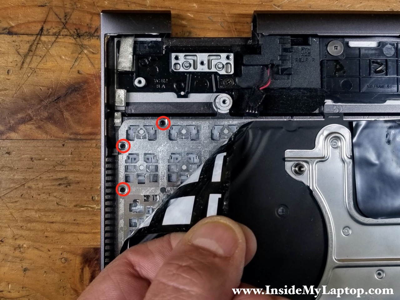
The HP Spectre x360 15-ch series laptop has a removable keyboard but it’s hard to remove. You’ll have to peel off the keyboard backlight without damaging it and remove many tiny screws securing the keyboard to the top case assembly.
Here’s the top case assembly with the motherboard removed.

vince
have you been successuful in adding 2—16gb memory sticks? everywhere including crucial says it will only support 16gb
Marcos Alba
Where is cmos battery?
IML Tech
I believe this model doesn’t have CMOS battery.
Marcos Alba
Muchas gracias por su respuesta, es bueno compartir conocimientos.
Les informo que mi Laptop es ese mismo modelo, y bueno decidà usarla con el adaptador AC ya que la baterÃa llego a su fin. La laptop tiene un rendimiento inestable sin la baterÃa, y cada vez que la enciendo me pone ” the cmos checksum is invalid”
La baterÃa es obligatoria, entra en undervolt de manera automática también.
IML Tech
Try this: https://www.youtube.com/watch?v=qpiGUojtr3E
Marcos Alba
He hecho todo eso, la verdad ha sido en vano, la Laptop no funciona energéticamente bien sin la baterÃa, inclusive actualicé la BIOS. Incluso las opciones de energÃa están bloqueadas aunque la intentes desbloquear con el comando cmd energy… No funciona. Las opciones del Bios están limitadas.