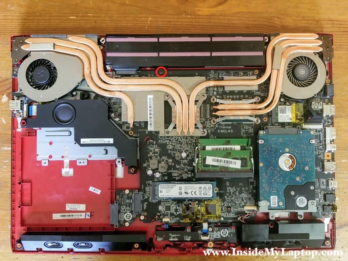
In this guide I show how to disassemble an MSI GE72 laptop model MS-1799.
I will take apart the laptop body and remove all internal components. For the LCD screen removal and replacement please follow this MSI GE62 guide.
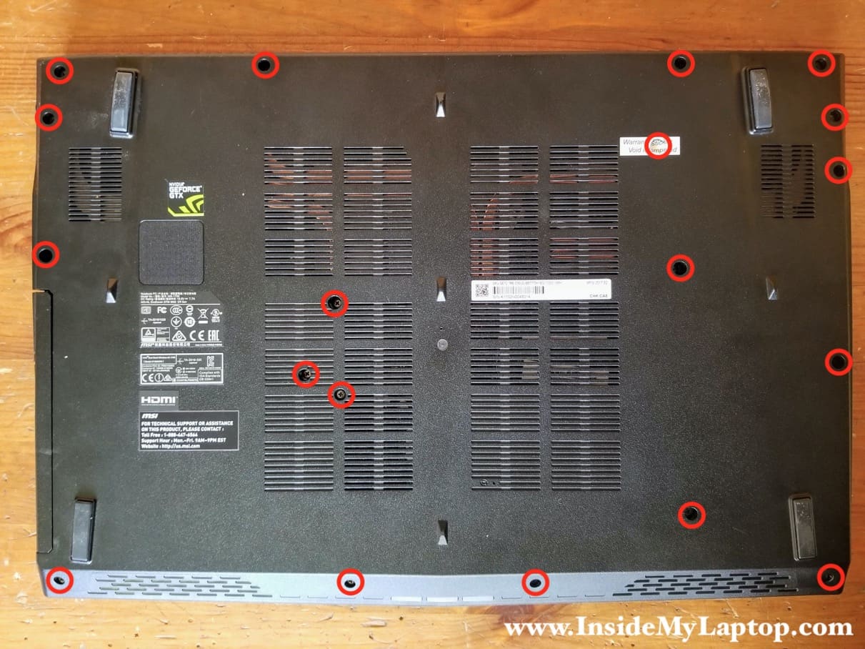
STEP 1.
Remove eighteen screws from the bottom cover.
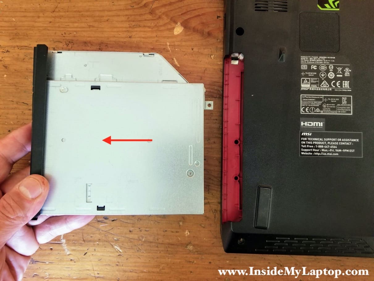
STEP 2.
Pull the optical drive out.
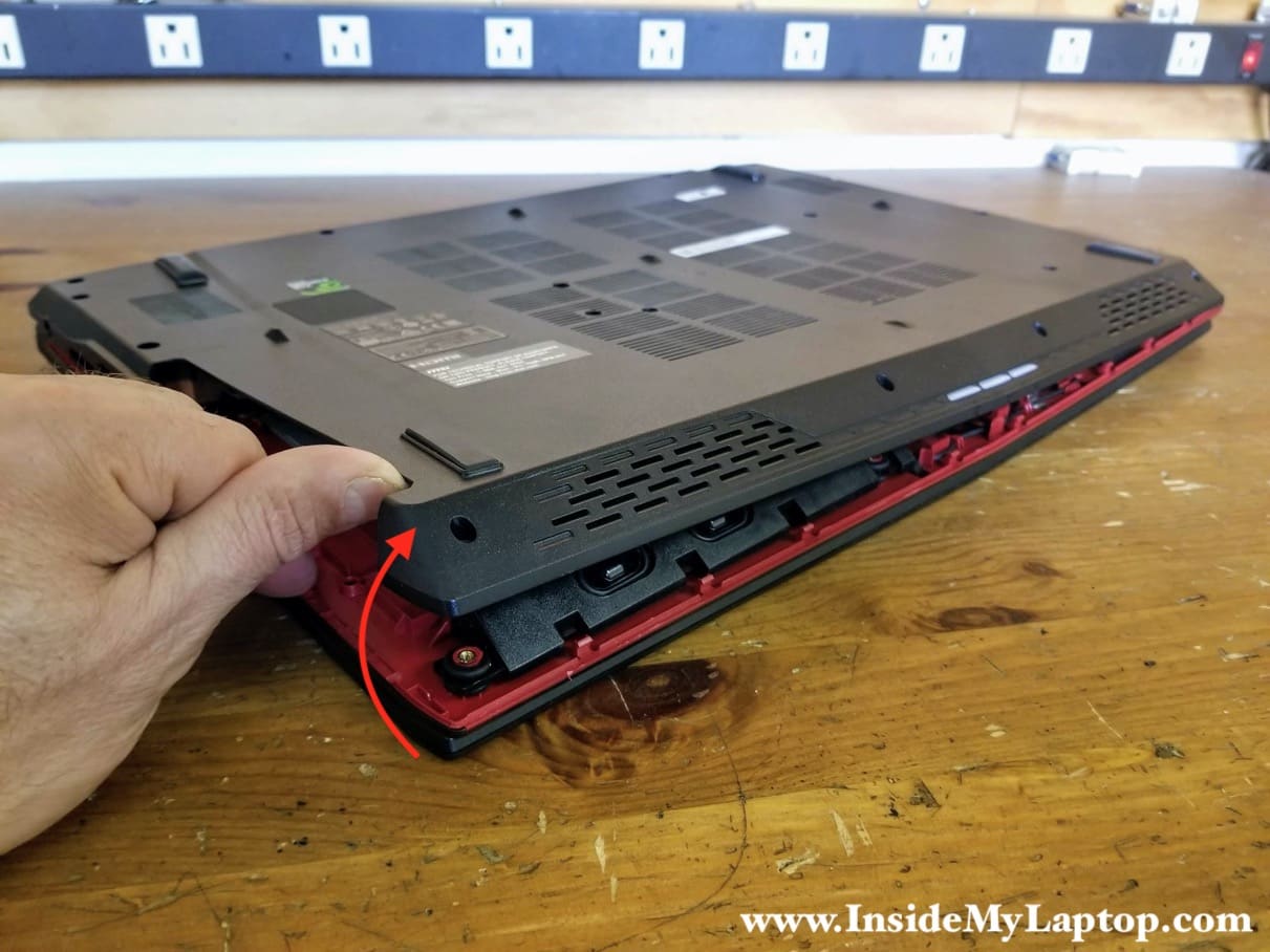
STEP 3.
Separate the bottom cover from the palmrest assembly. There are many hidden latches securing the bottom cover. You’ll have to wiggle the cover and use a case opening tool to release the latches.
It’s easier to remove the bottom cover if you start from the optical drive side. Remove the cover.
STEP 4.
Remove one screw securing the main battery.
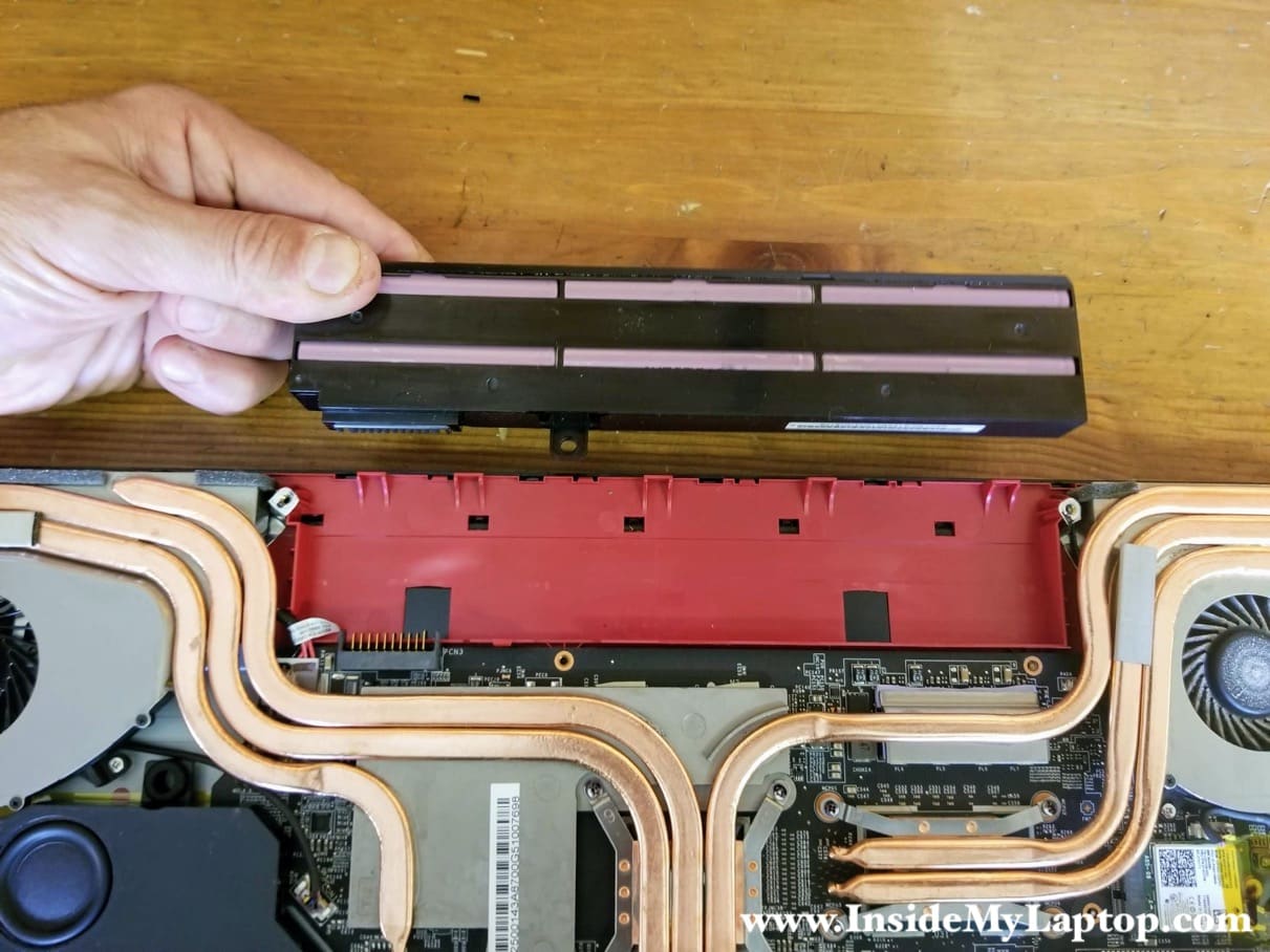
STEP 5.
Lift up the battery to disconnect it from the motherboard. Remove and replace the battery if necessary.
STEP 6.
Remove one screw securing the 2.5″ hard drive bracket.

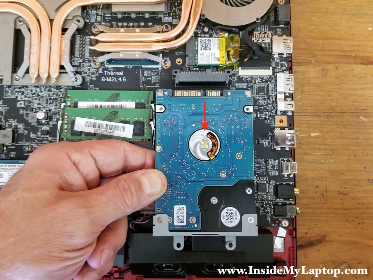
STEP 7.
Disconnect the hard drive from the SATA port and remove the drive. You can upgrade this hard drive with a 2.5″ solid state drive to speed up the laptop.
The boot drive is the solid state drive. The SSD secured by one screw.
There is a thermal pad between the SSD and the motherboard. It might be necessary to apply some reasonable force to separate the SSD from the motherboard.
I will leave this drive attached to the motherboard but you can remove it if necessary.
This is m.2 SATA solid state drive (type 2280).

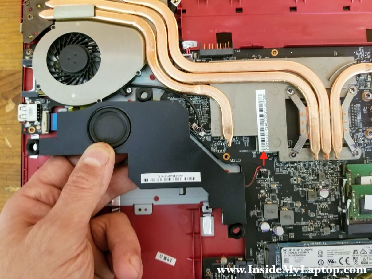
STEP 8.
Lift up the subwoofer and disconnect the speaker cable from the motherboard. Remove the subwoofer.
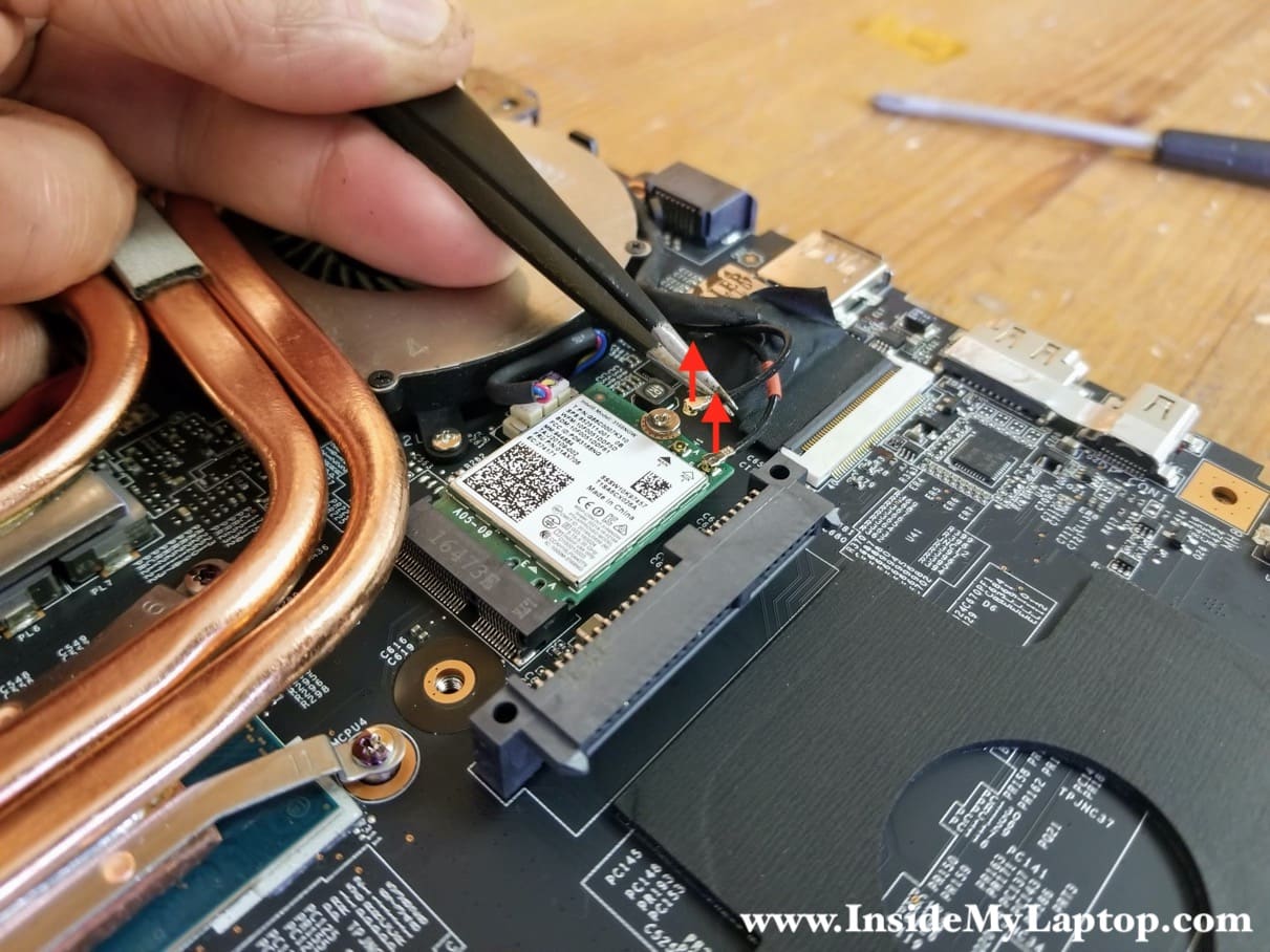
STEP 9.
Carefully disconnect both wireless antennas from the wireless card.
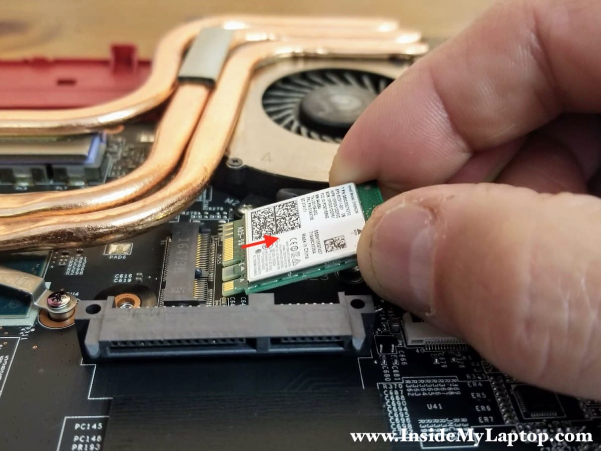
STEP 10.
Remove one screw securing the Wi-Fi card and pull the card out.
STEP 11.
Remove two screws securing the right cooling fan.
Disconnect the I/O cable from the USB SD card reader board.

Here’s how to release the I/O cable.
Lift up the locking tab (red arrow) to unlock the connector and pull the I/O cable out (yellow arrow).

STEP 12.
Remove two screws securing the left cooling fan.
Disconnect the display cable from the motherboard.

Here’s how to disconnect the display cable.
Unlock the connector and pull the cable out.

STEP 13.
Remove the display cable and Wi-Fi antenna cables from the guided path on the side of the fan.

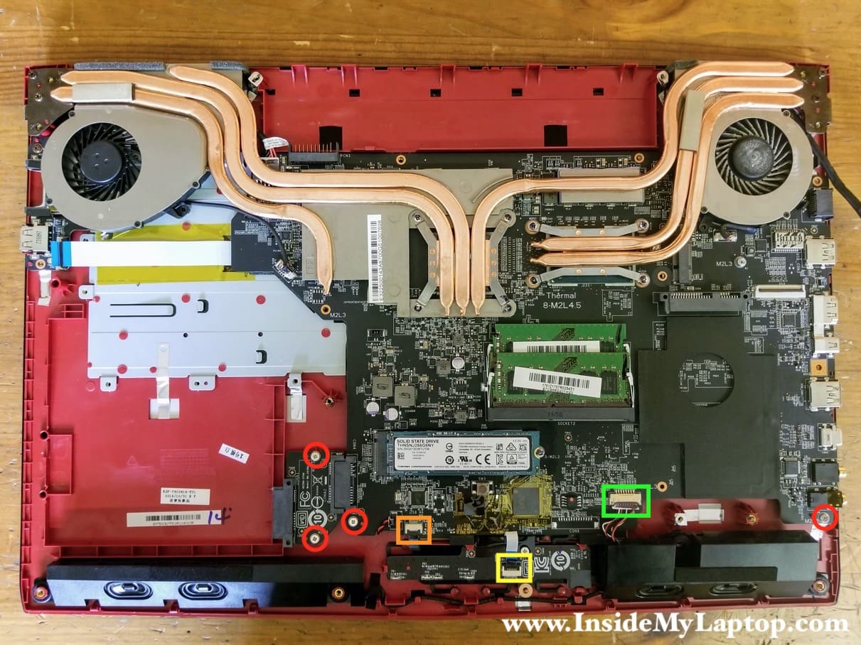
STEP 14.
Remove four screws securing the motherboard.
Disconnect the following color-coded cables:
– Touchpad cable (orange).
– Touchpad button board cable (yellow).
– Speaker cable (green).
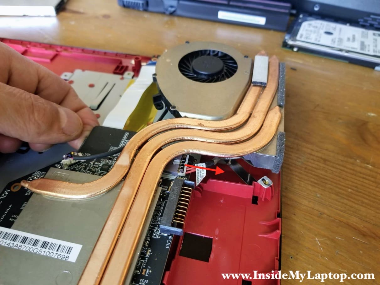
STEP 15.
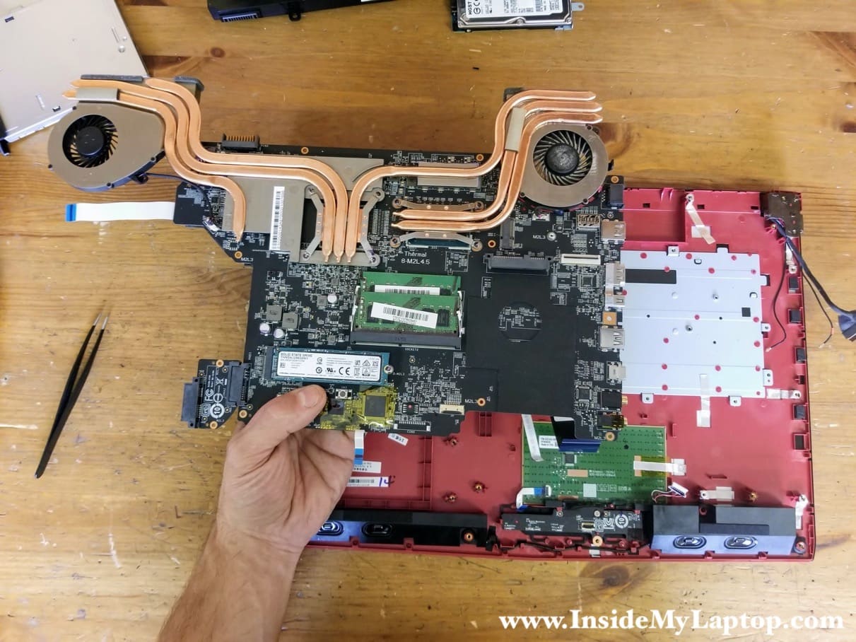
Lift up the motherboard and disconnect the DC power jack cable which is partially hidden under the heatsink.
STEP 16.
Separate the motherboard from the top case. Be careful, the keyboard cables are still attached to the other side of the motherboard.

STEP 17.
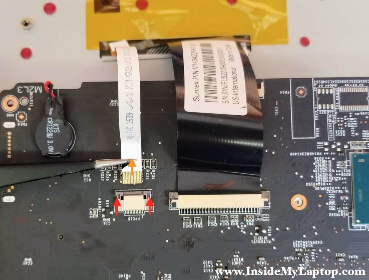
Turn the motherboard upside down so you can access and disconnect the keyboard cables. There are two of them: the backlight cable (yellow) and keyboard cable (orange).

Here’s how to disconnect the keyboard cables.
Slide the locking tab about 2 millimeters away from the connector (red arrows). Pull the cable out (orange arrow).
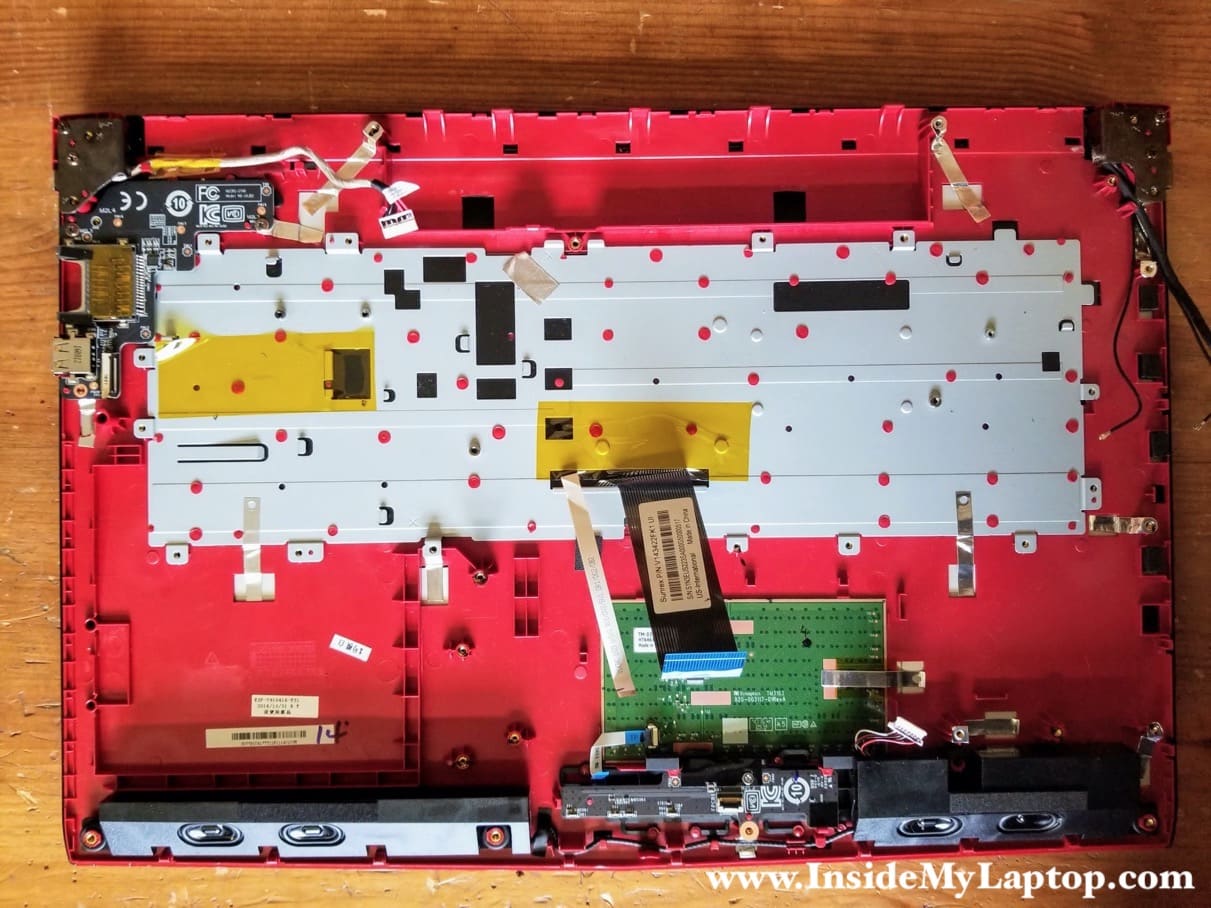
STEP 18.
Remove the motherboard assembly.
MSI GE72 laptop has the keyboard permanently attached to the top case. The keyboard cannot be easily removed and replaced. You can try replacing it this way.
STEP 19.
Remove two screws securing the USB SD card reader board.

STEP 20.
Remove the USB SD card reader board.

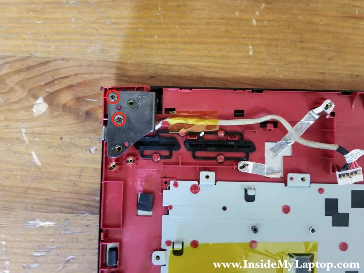
STEP 21.
The DC power jack is mounted under the right display hinge.
Remove two screws securing the right hinge.
STEP 22.
Lift up the display hinge and remove the DC power jack harness.
