In today’s guide I show how to disassemble a Dell XPS 13 9370 9380 (model P82G) laptop.
Dell XPS 13 9370 9380 design highlights:
– All memory soldered to the motherboard. There are no slots available for RAM upgrade.
– The cooling fan assembly can be easily accessed and replaced.
– The wireless card is integrated into the motherboard.
– The headphones jack is a replaceable part.
– The keyboard can be separated from the top case.
For this disassembly you will need only a few basic repair tools: Torx T5 screwdriver, Phillips #0 screwdriver, plastic spudger and needle nose tweezers.
Base cover and battery removal
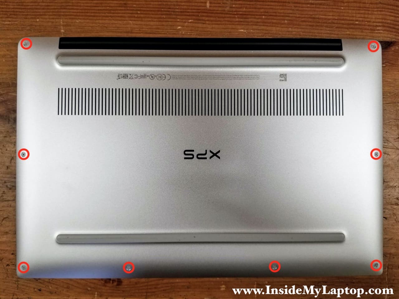
STEP 1.
Remove eight Torx T5 screws from the base cover.
STEP 2.
Start separating the base cover from the top case assembly using a plastic spugder. I wouldn’t recommend using a regular metal case opener tool here because you can accidentally scratch the case.
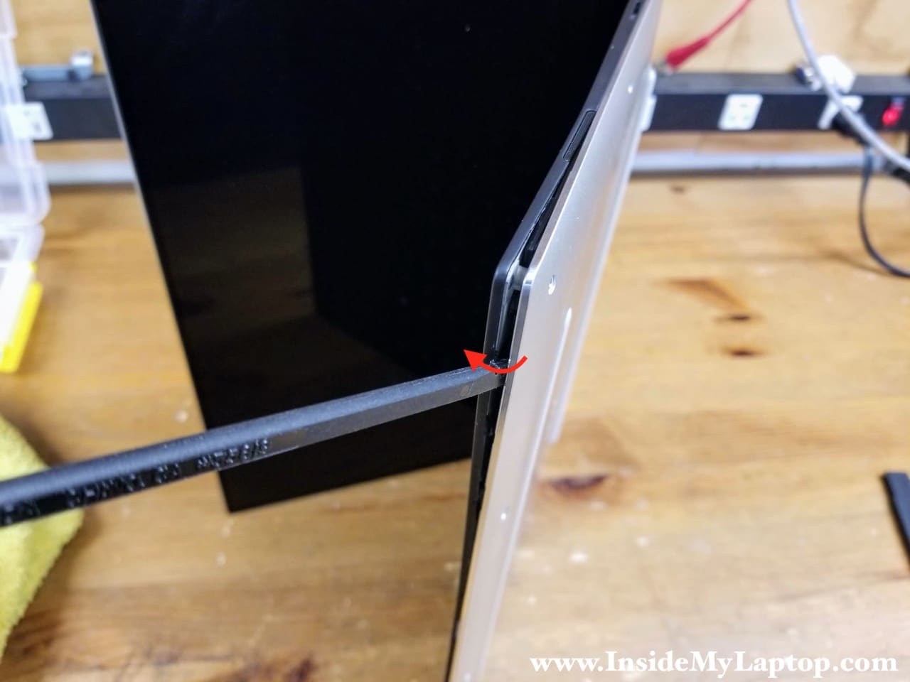
Be careful while using the spudger on the front side of the laptop. There is a thin cable routed along the front side. If you insert the spudger too far, you can damage this cable.
STEP 3.
Continue removing the base cover with your hands. Wiggle the cover to release all hidden latches securing it to the top case. In Dell XPS 13 9370 9380 laptop the base cover and the top case fitted very tightly.
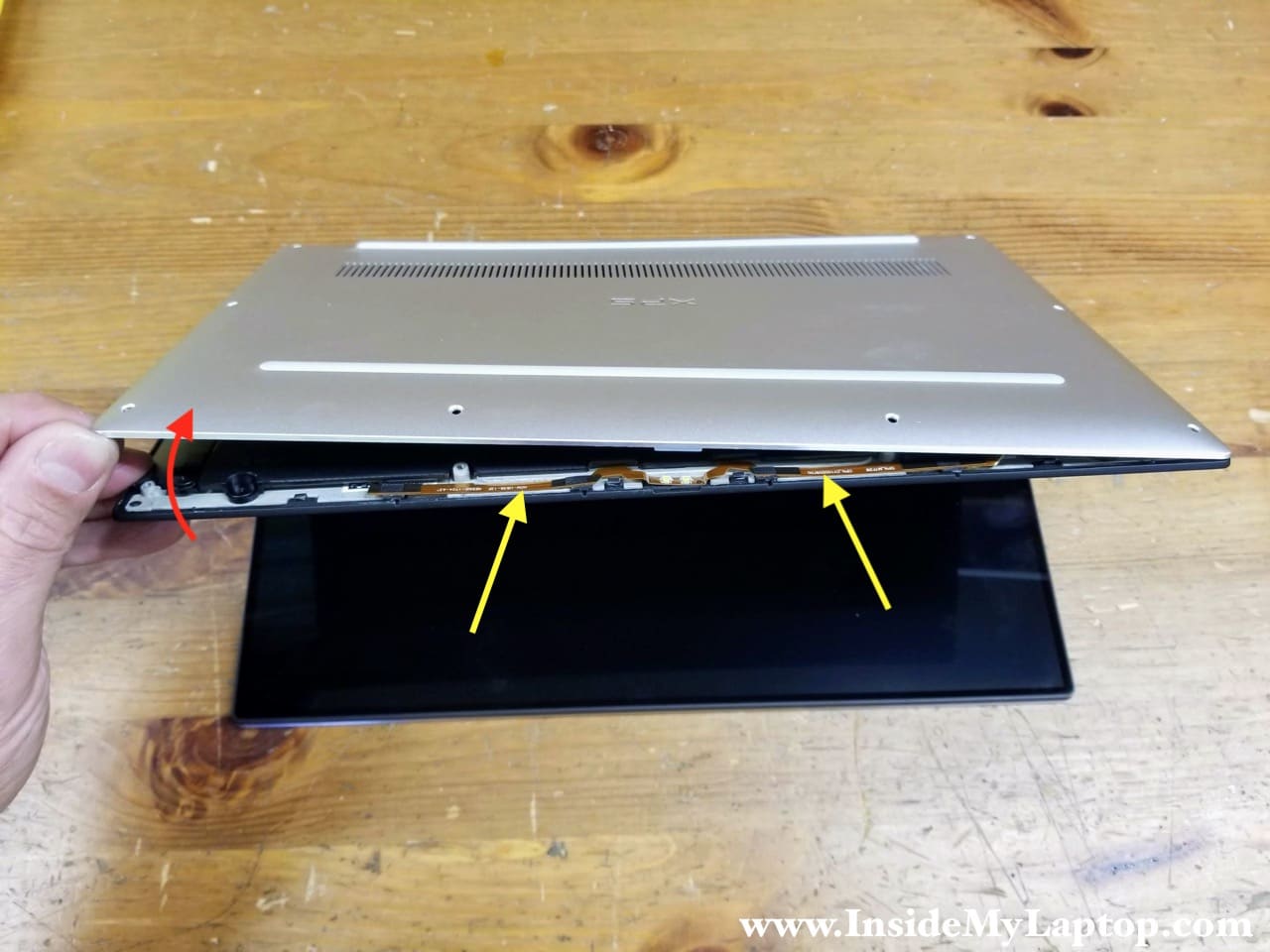
STEP 4.
Remove the base cover.

STEP 5.
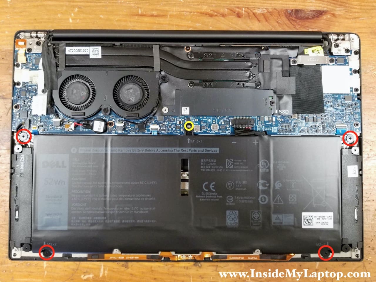
Remove four large screws (red) and one small screw (yellow) attaching the battery to the top case.
STEP 6.
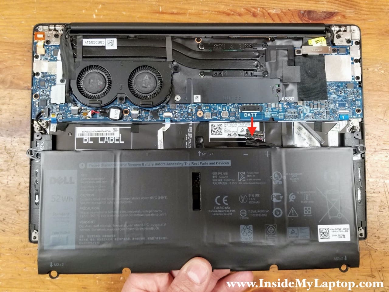
Lift up the battery and disconnect the battery cable from the motherboard.
Dell XPS 13 9370 9380 battery model: DXGH8. Dell spare part number: 0H754V.
Solid state drive removal
Dell XPS 13 9370 9380 laptop supports PCEe/NVMe Gen 3×4 M.2 solid state drives (type 2280).
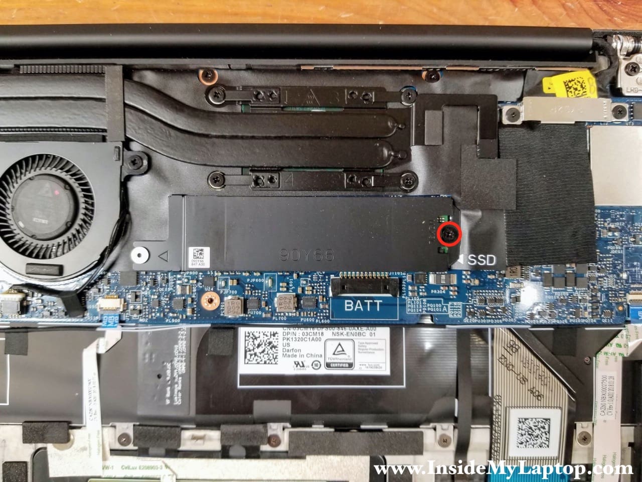
The solid stat drive is mounted under the black shield/heatsink. There is a layer of thermal pad between the shield and the SSD. It might be necessary to apply a little bit of force to separate the shield from the SSD because the thermal pad is sticky.
STEP 7.
Remove one screw securing the SSD shield/heatsink.
STEP 8.
Lift up the right side of the shield. When the shield is separated from the SSD, pull the left side from under the metal knob (yellow arrow).
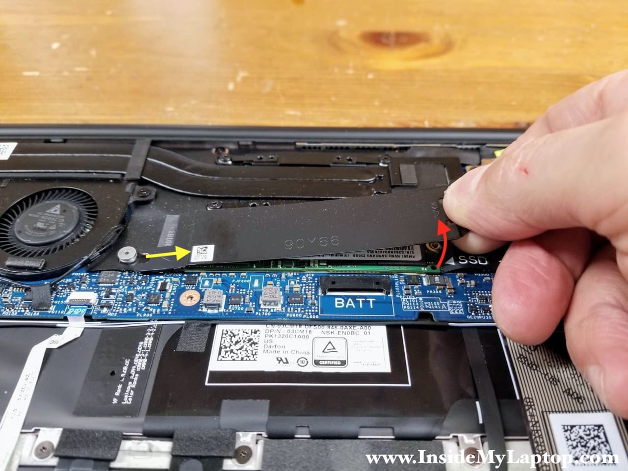
There is a layer of thermal pad under the SSD. It might be necessary to apply a little bit of force to separate the SSD from the motherboard.
STEP 9.
Lift up the right side of the SSD and pull it out of the slot.

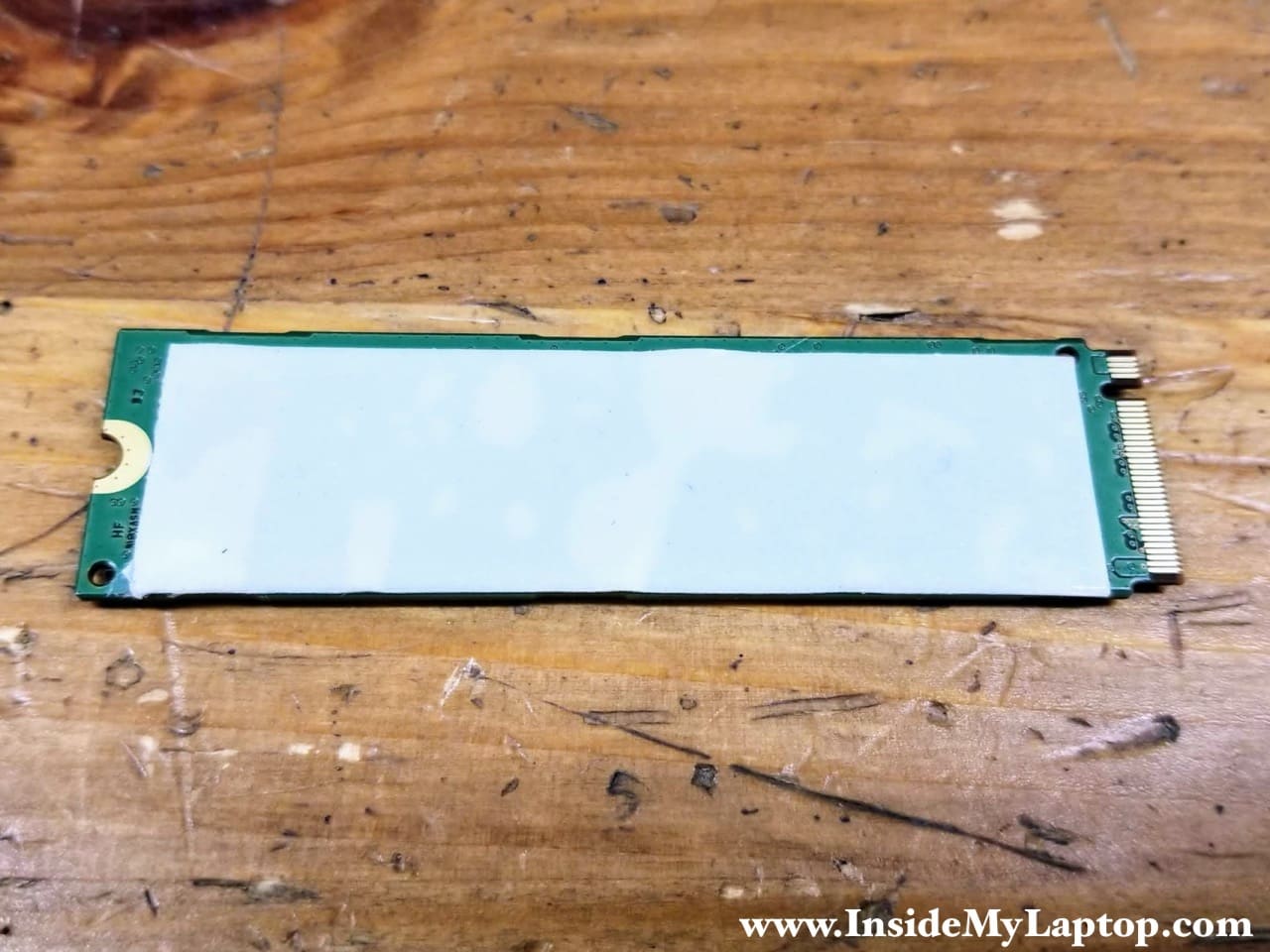
Here’s the other side of the SSD with a layer of thermal pad applied to it.
Cooling fan assembly removal
Dell XPS 13 9370 9380 has two cooling fans merged into one assembly. Before removing the cooling fan assembly we have to disconnect the webcam cable because it’s routed above the left fan.
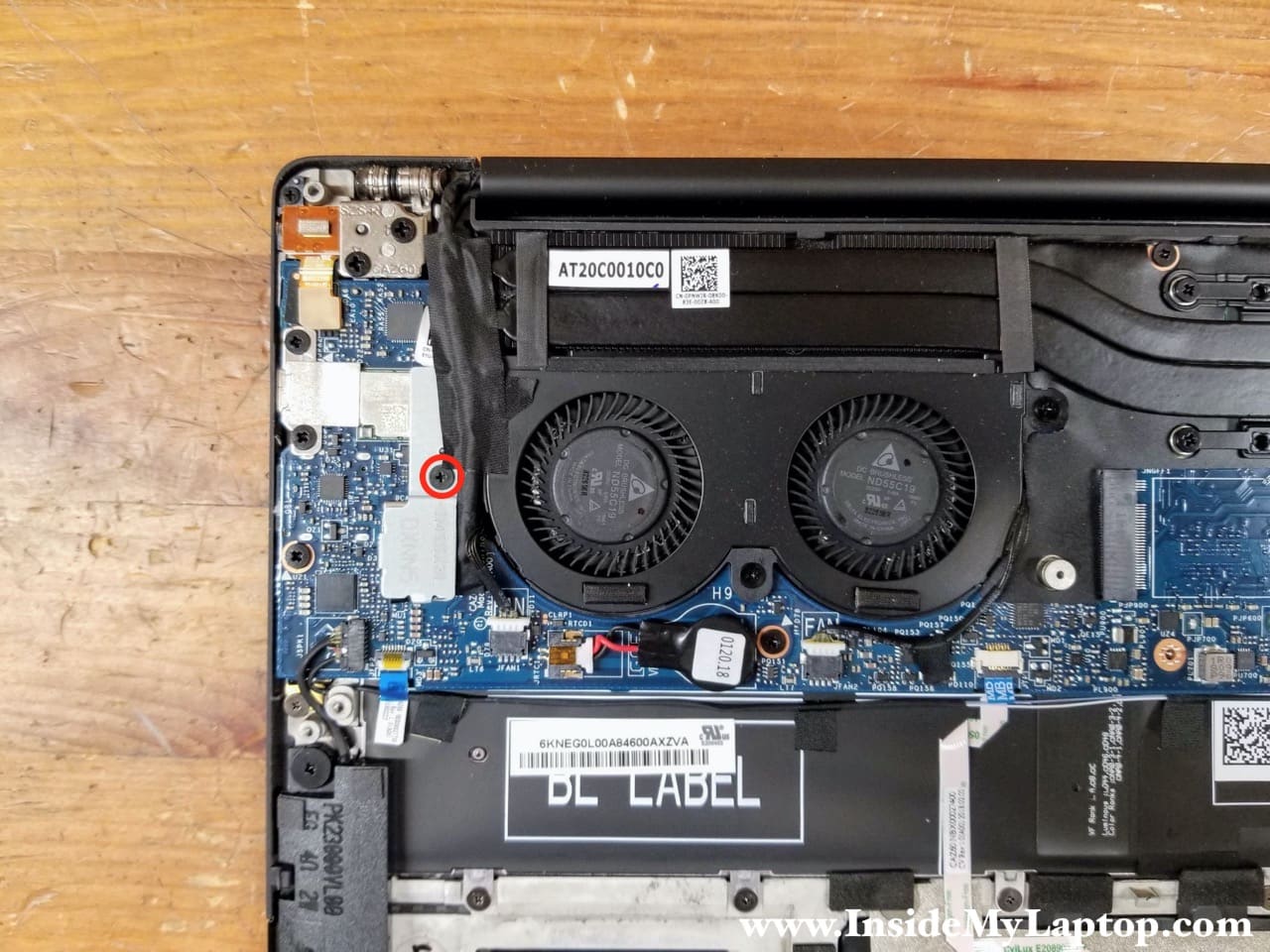
STEP 10.
Remove one screw securing the webcam and wireless antenna cover.
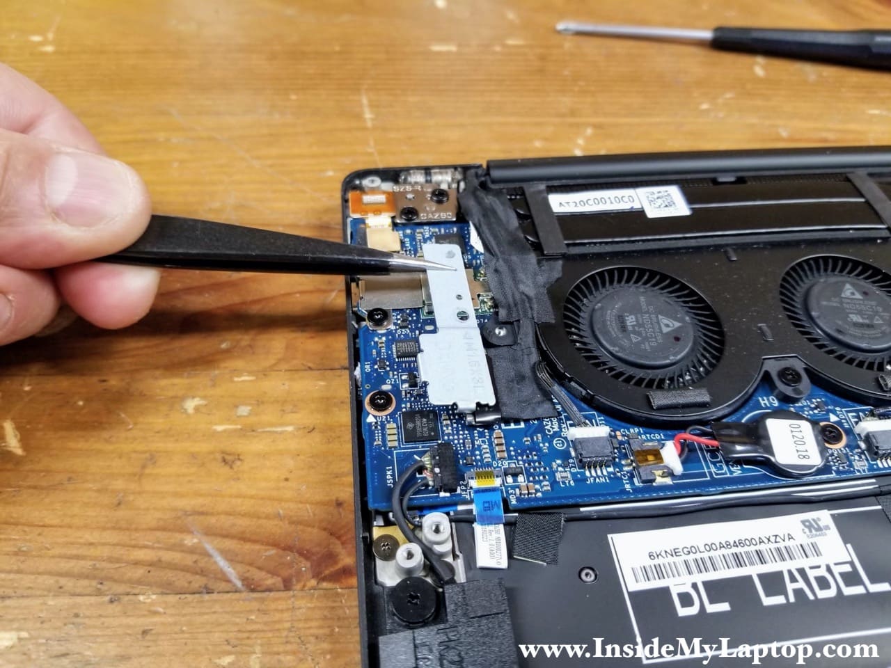
STEP 11.
Remove the cover.
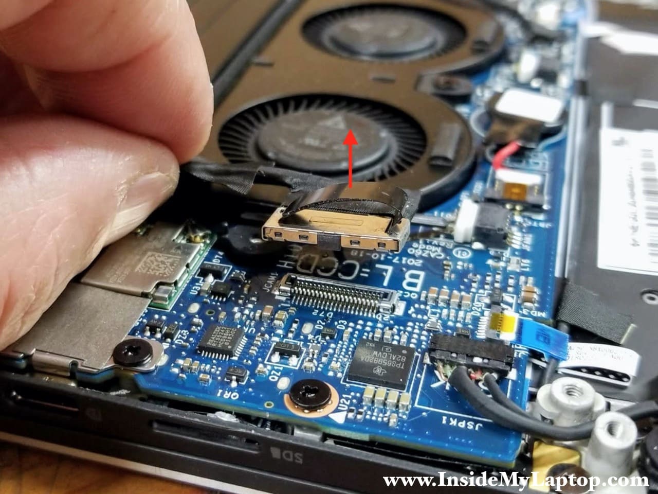
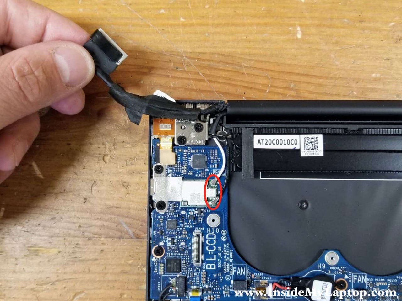
STEP 12.
Disconnect the webcam cable from the motherboard. There is a black tab on the top of the connector. Pull it up to unplug the cable from the connector on the motherboard.
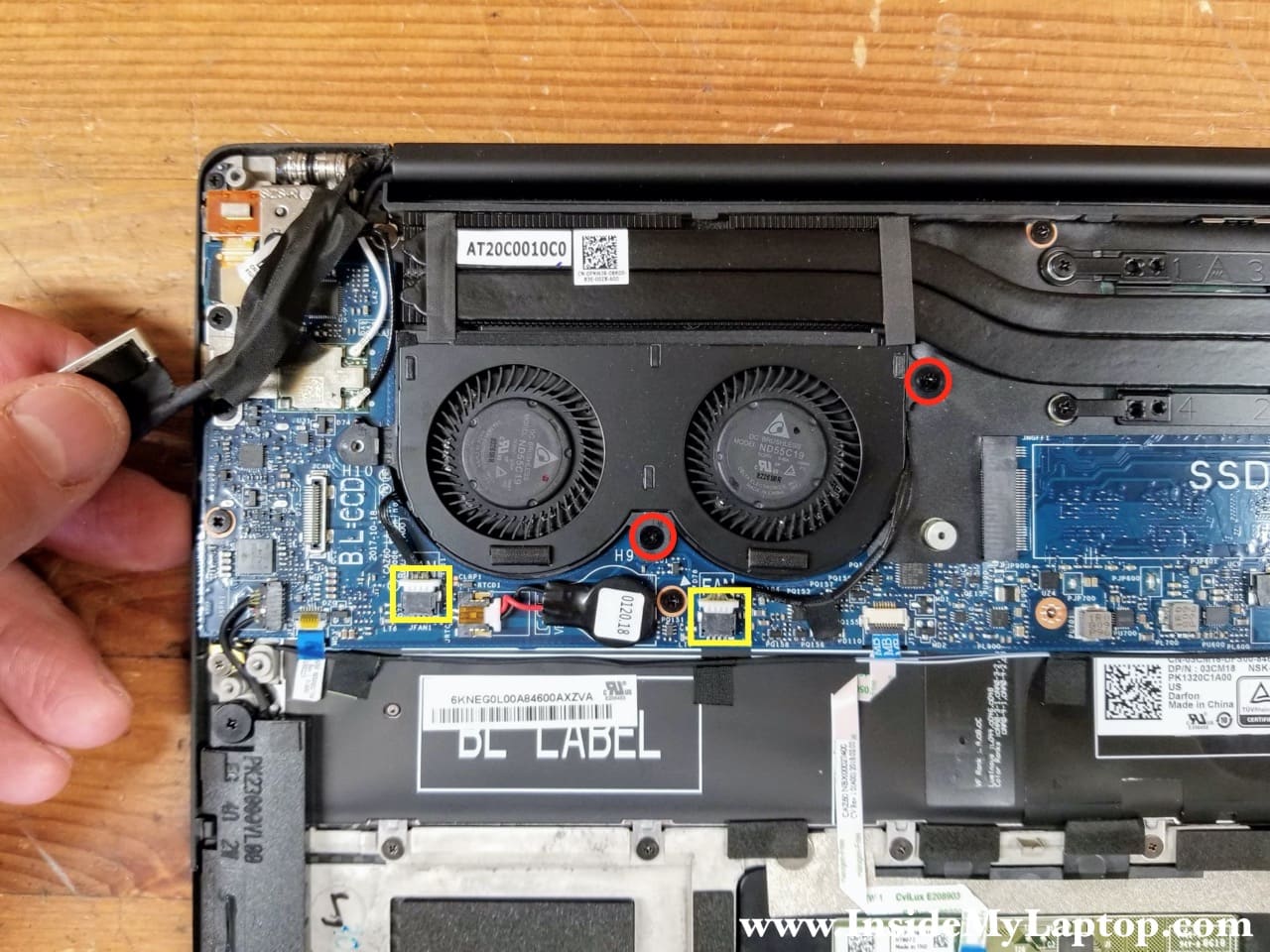
STEP 13.
Move the webcam cable aside. Remove two screws securing the cooling fan assembly. Disconnect both fan cables from the motherboard.
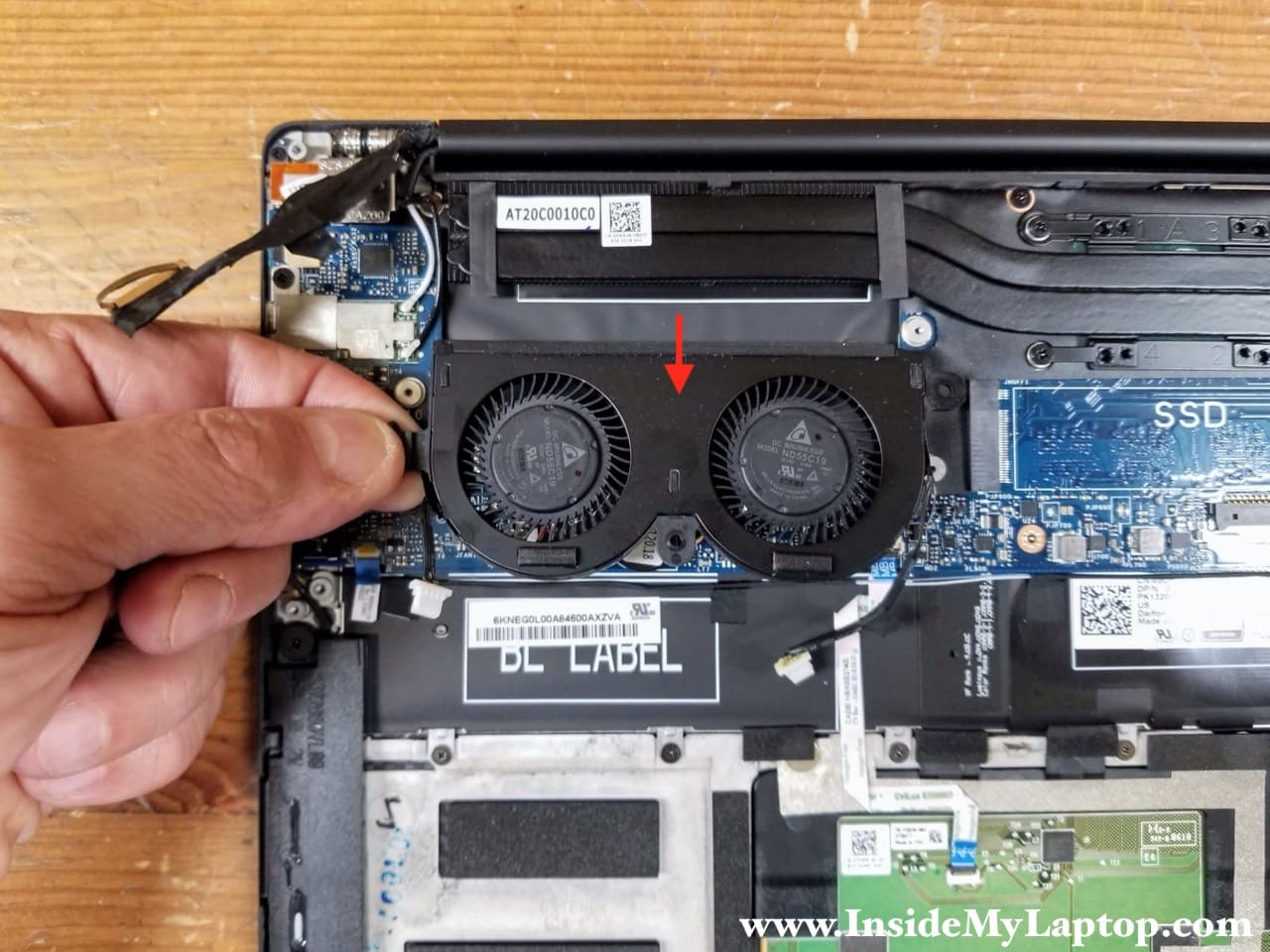
STEP 14.
Pull the cooling fan assembly from under the heatsink and remove it.
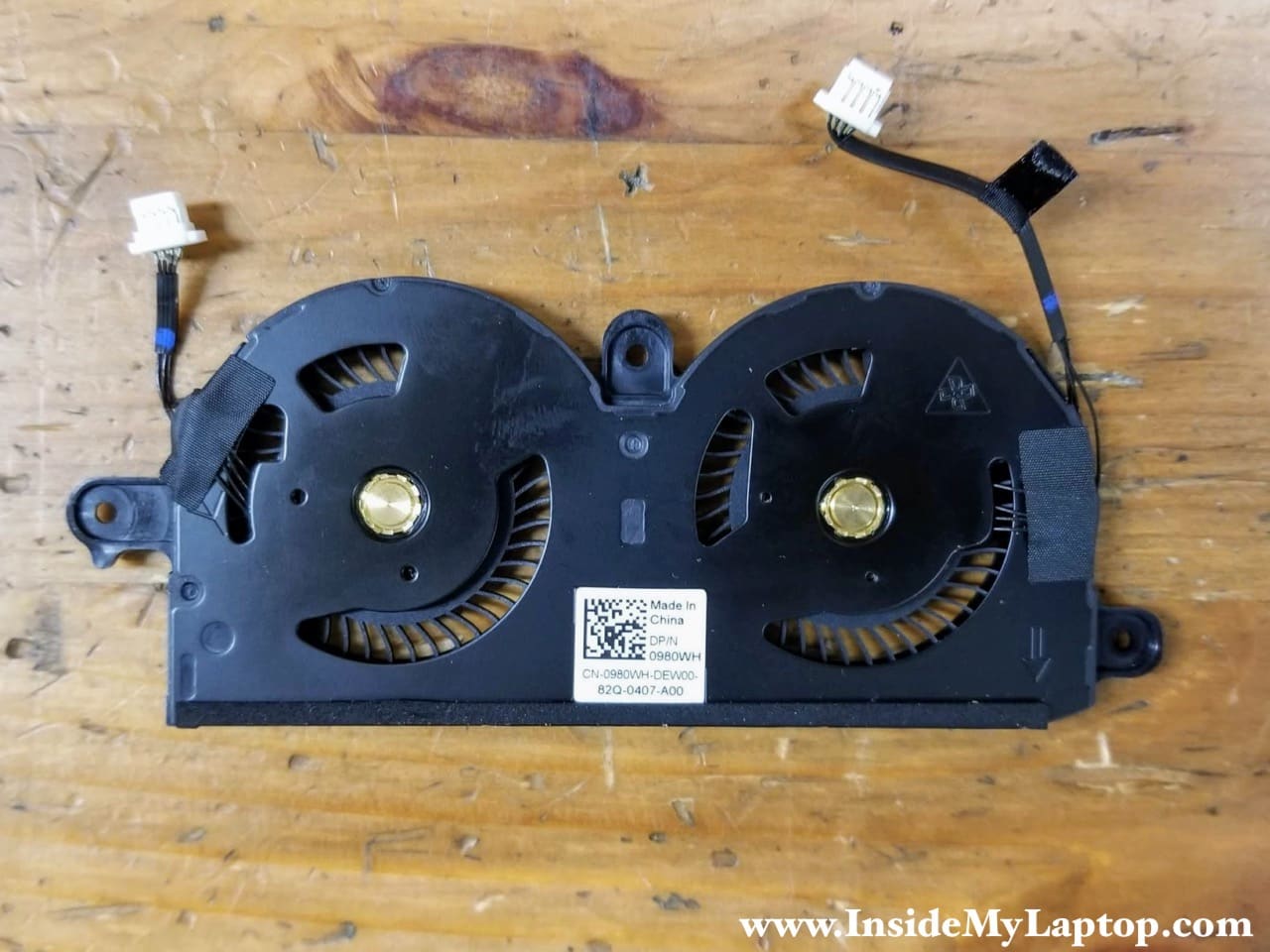
Here’s the other side of the fan assembly. Both fans are permanently mounted so if one of them fails it’s necessary to replace the entire assembly.
Dell spare part number for Dell XPS 13 9370 9380 fan assembly: 0980WH.
Display assembly removal
STEP 15.
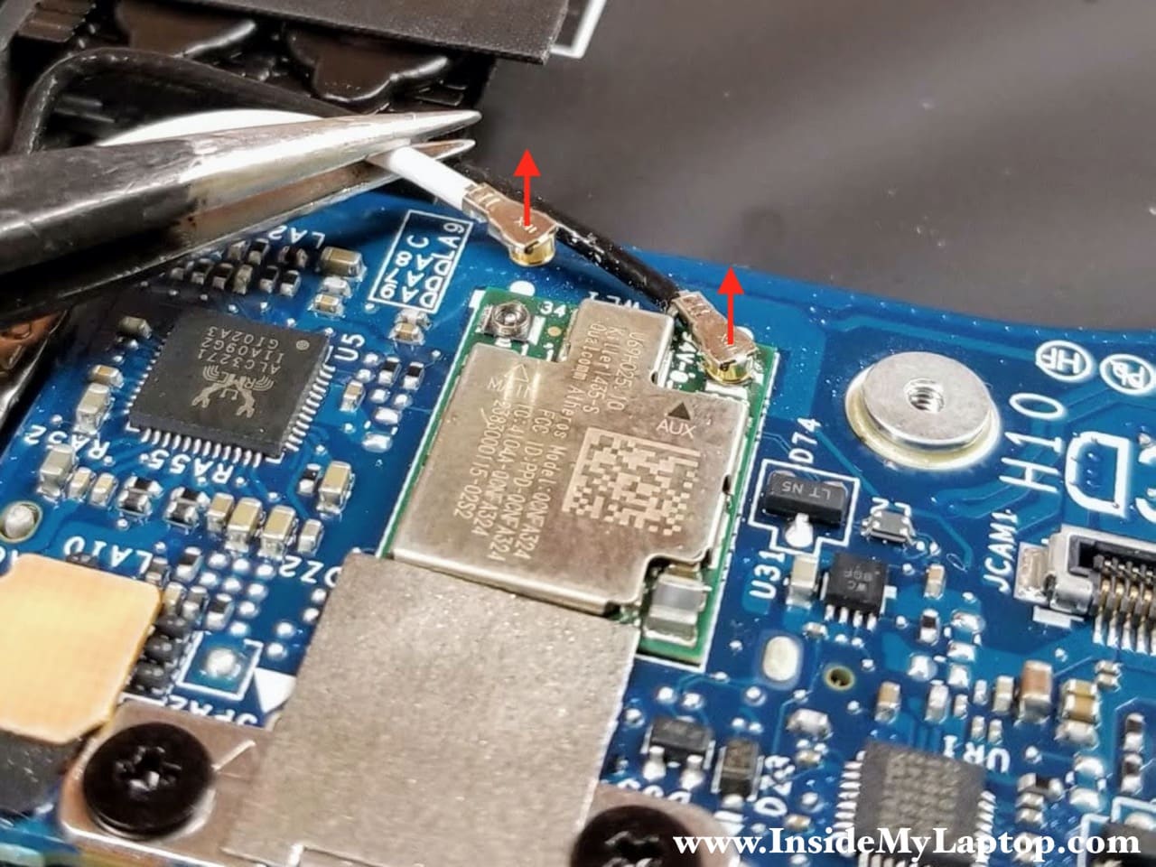
Disconnect two antenna cables from the wireless card. The wireless card is integrated into the motherboard and cannot be removed or replaced.
In order to disconnect the antenna cables simply lift them up and un-snap from the connector on the wireless card.
STEP 16.
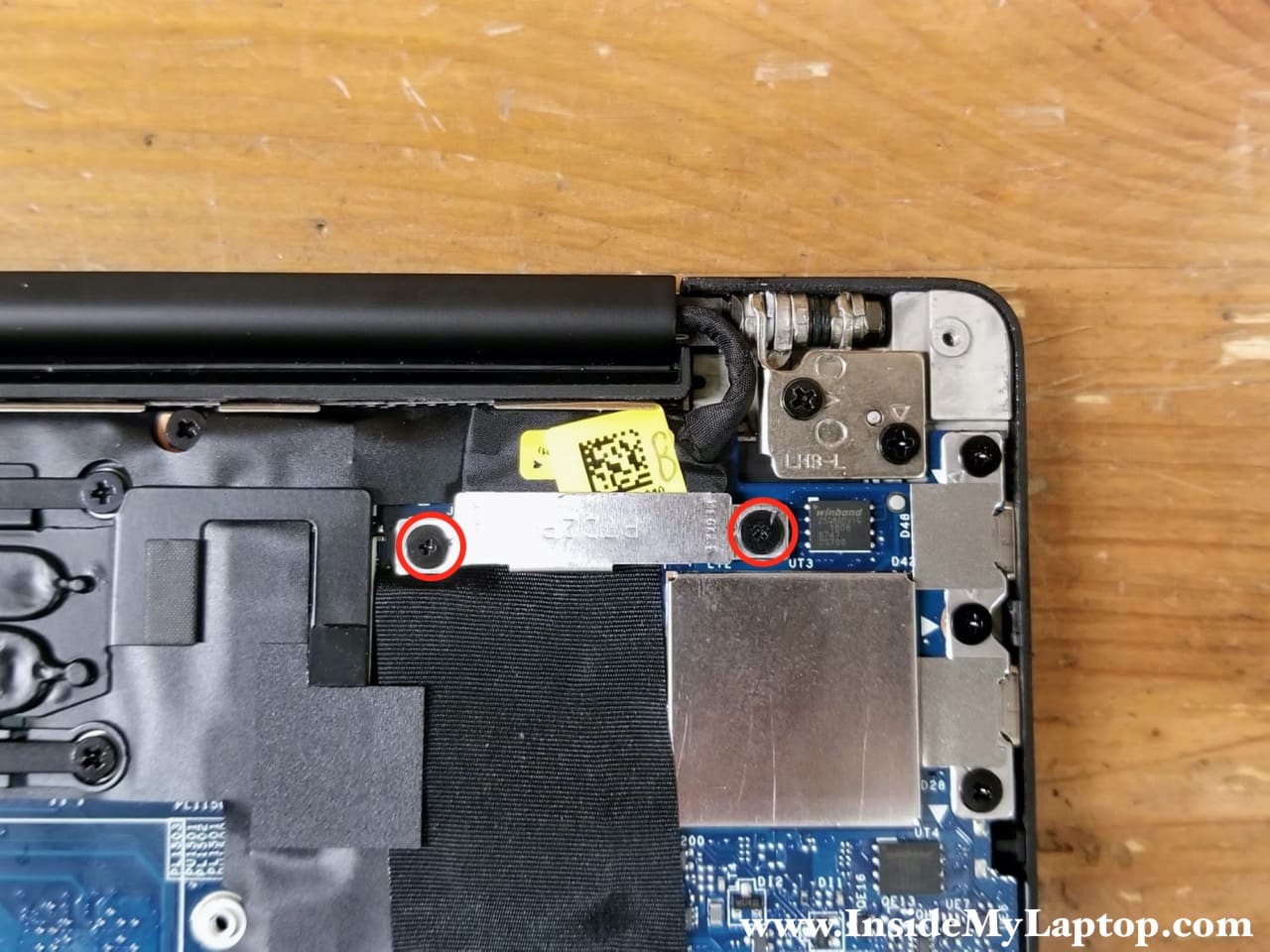
Remove two screws from the display cable bracket. Lift up and remove the bracket.
STEP 17.
Disconnect the display cable from the motherboard. Lift up the connector by the black tab located on the top.

STEP 18.
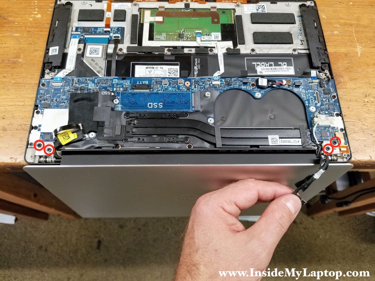
Open the display panel 90 degrees and place the laptop upside down on the edge of the desk. Remove four screws securing the display panel hinges.
STEP 19.
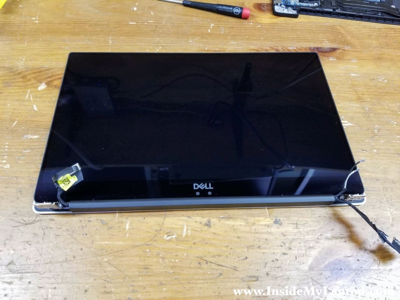
Separate the display panel from the top case and remove it.
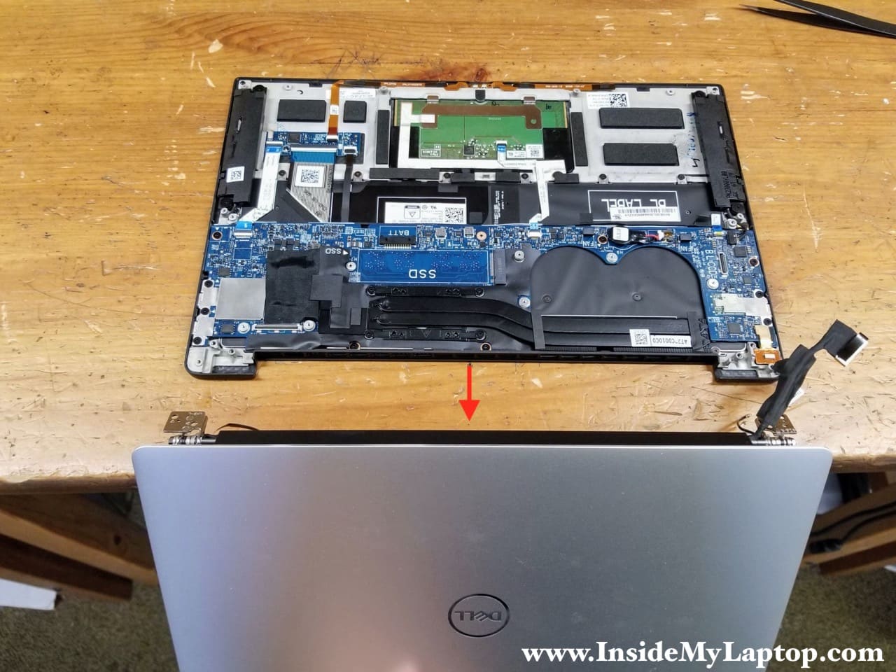
In Dell XPS 13 9370 9380 laptop the display panel is a sealed unit and the LCD screen cannot be removed. If you have a failed LCD screen it’s necessary to replace the entire display assembly.
Headphones jack removal
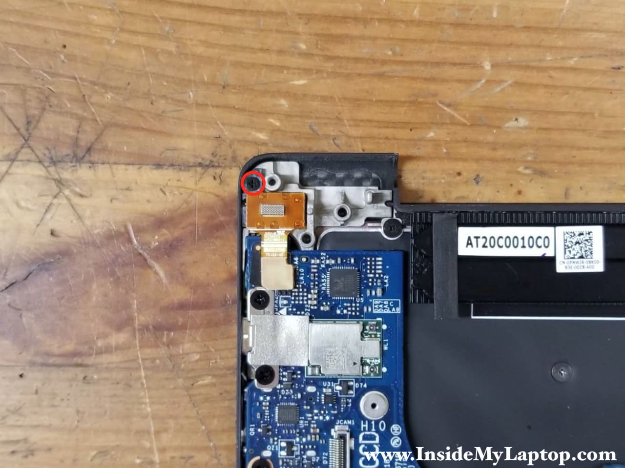
STEP 20.
Remove one screw securing the headphones jack.
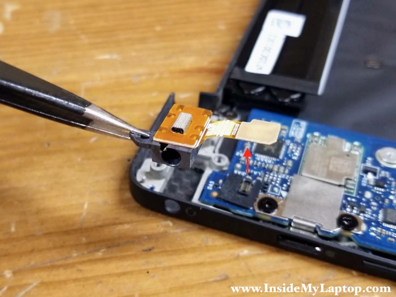
STEP 21.
Disconnect the headphones jack cable from the motherboard. Lift up and remove the headphones jack.
Motherboard removal
STEP 22.
Remove ten screws attaching the motherboard to the top case.
Disconnect the following color-coded cables:
– Speaker cable (orange).
– Fingerprint reader cable (green).
– Touchpad cable (yellow).
– Keyboard controller cable (pink).
The BIOS battery can be removed too but I will leave it connected to the motherboard in order to preserve the BIOS settings.

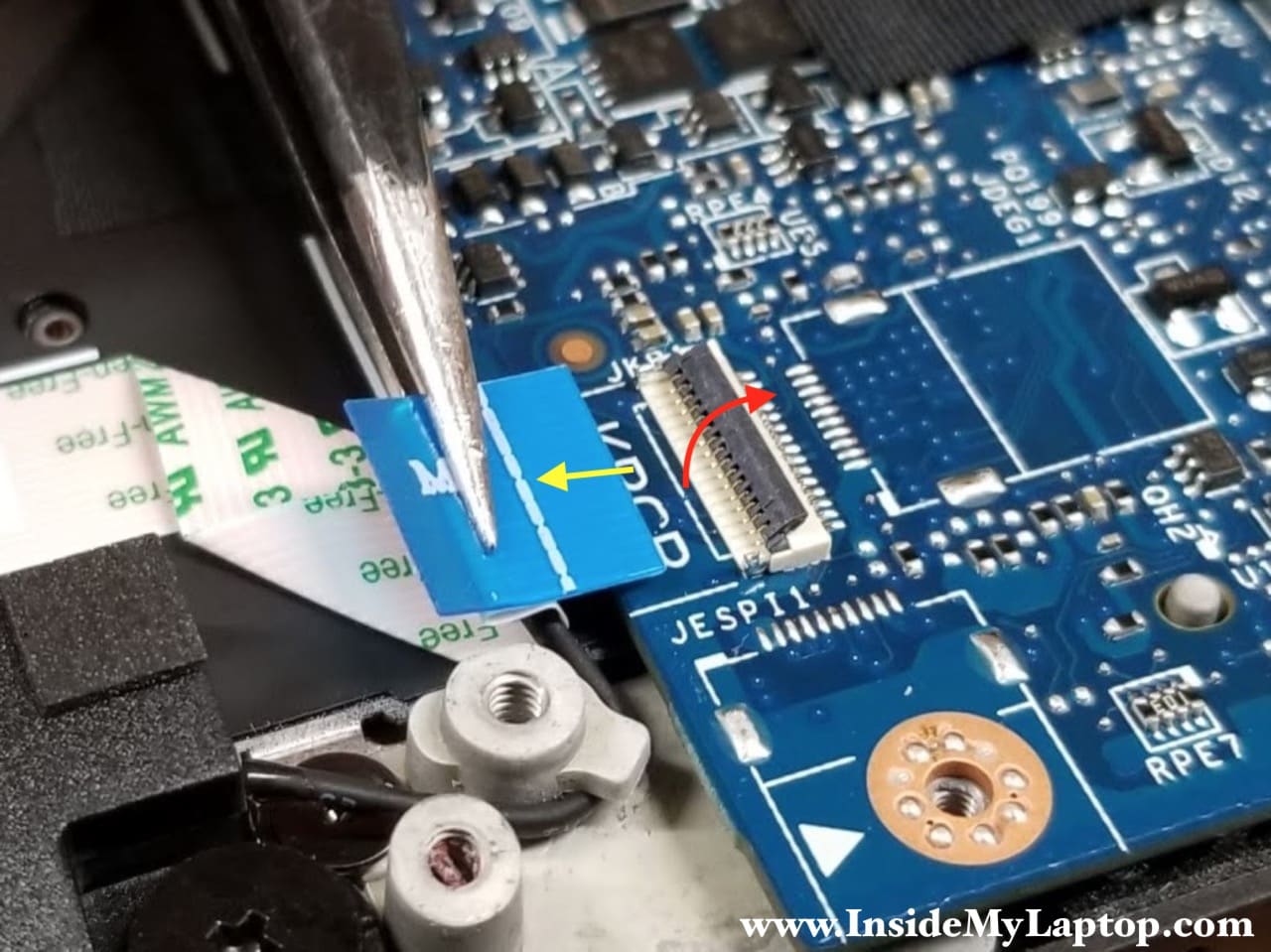
Here’s how to disconnect the flat cables.
1. Unlock the connector by lifting up the locking tab (red arrow).
2. Pull the cable out of the connector (yellow arrow).
STEP 23.
Start removing the motherboard from the top case assembly.
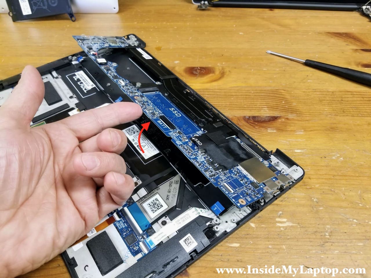
STEP 24.
Remove the motherboard.

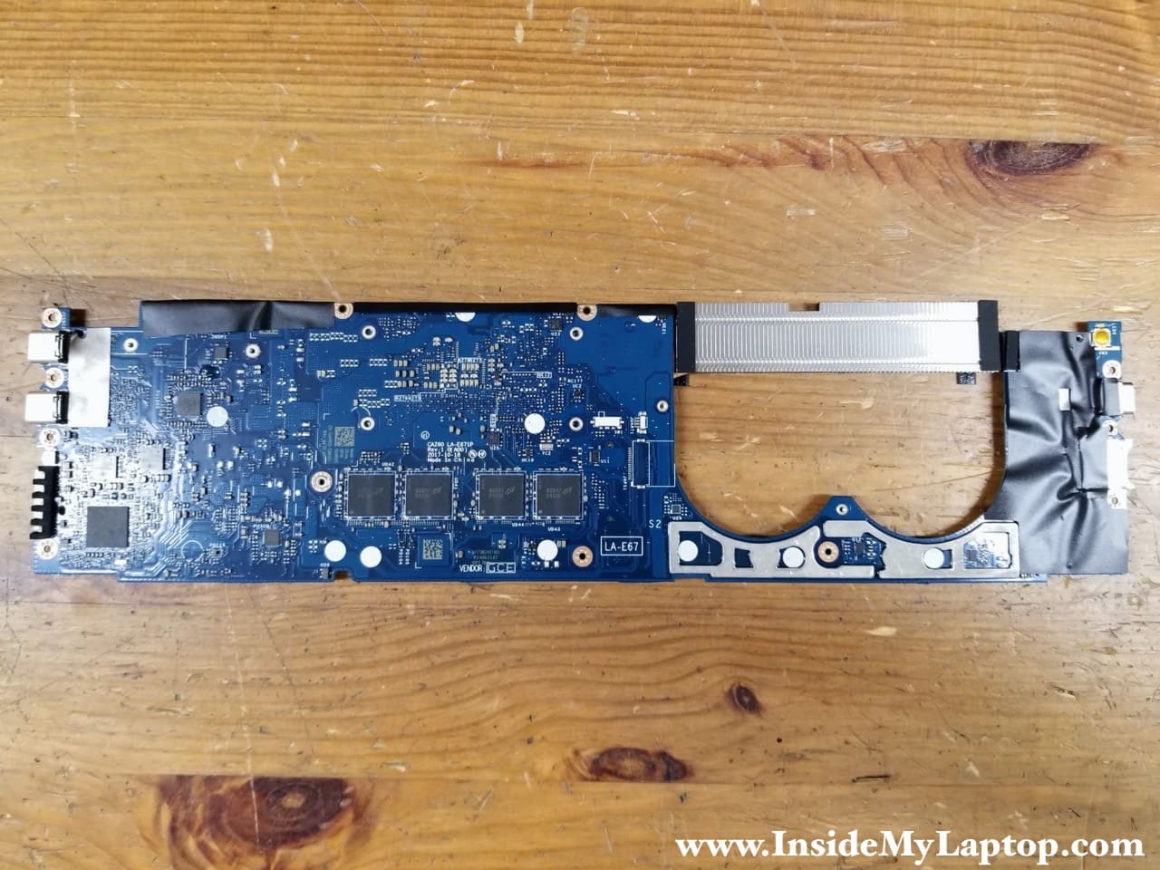
Here’s the other side of the motherboard.
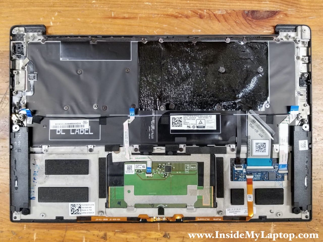
Here’s the top case assembly with the motherboard and the display panel removed.
Dell XPS 13 9370 9380 has a removable keyboard.
When you restart the laptop after the complete disassembly, it might take a while to boot the OS. The laptop has to go through the the initialization process and it will restart a few times during the initialization. Eventually it should turn on to the BIOS setup menu where you have to enter the correct date and time.