In this guide I explain how to disassemble Dell Inspiron 15 3565 or 3567 laptop (model P63F). It’s possible this guide will work for some other model in the Dell Inspiron 15 3000 series computer line.
I will walk you through the step-by-step internal component removal procedure. The LCD screen removal and replacement will be published in the next article (you’ll find a link in the step 17).
STEP 1.
Unlock the remove the main battery. This is battery type M5Y1K.

STEP 2.
There are 5 latches securing the keyboard to the palmrest assembly.
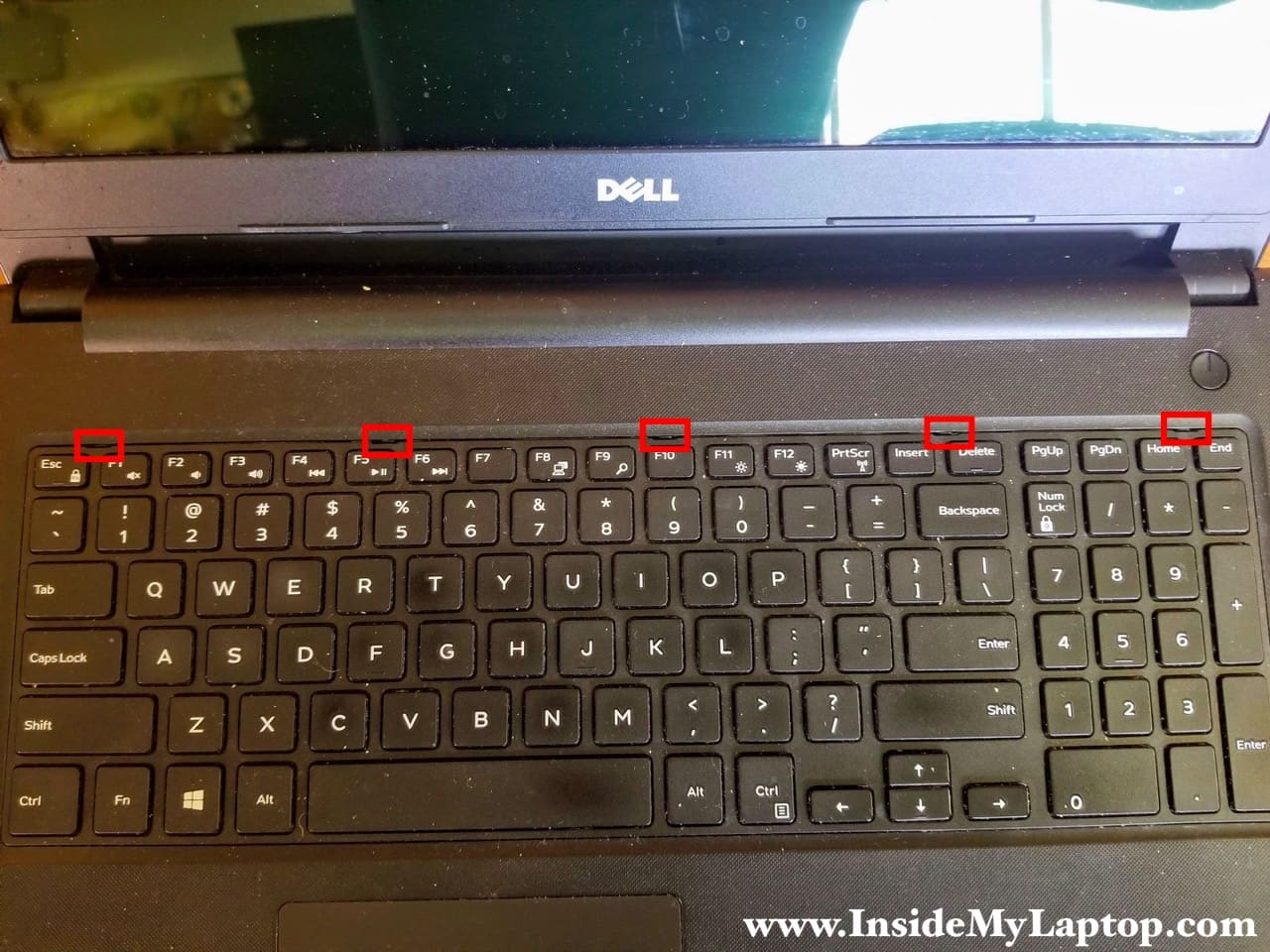
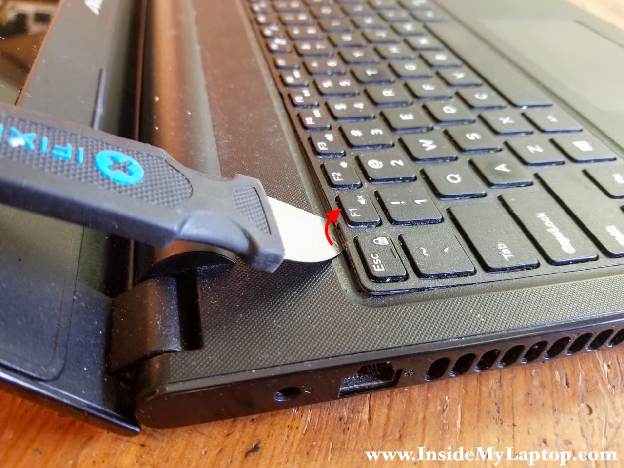
I’m using a metal case opener for this step.
Push the latch inside the case and at the same time lift up the keyboard.
After one latch is release, move to the next one.
STEP 3.
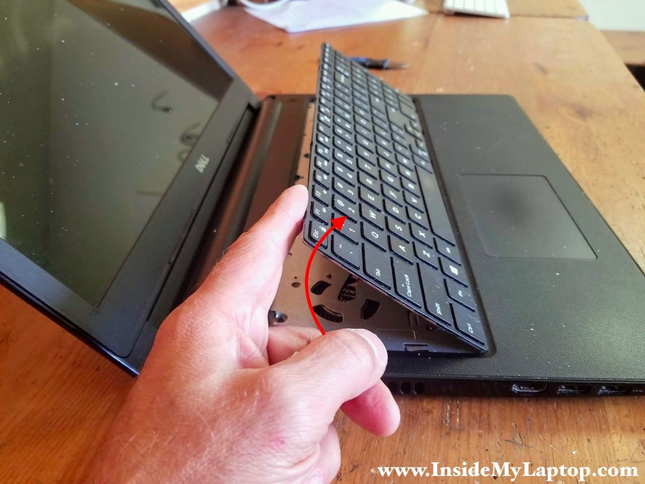
Unlock all five latches and separate the keyboard from the palmrest.
Place the keyboard upside down.
STEP 4.
The keyboard cable connector located under the keyboard.
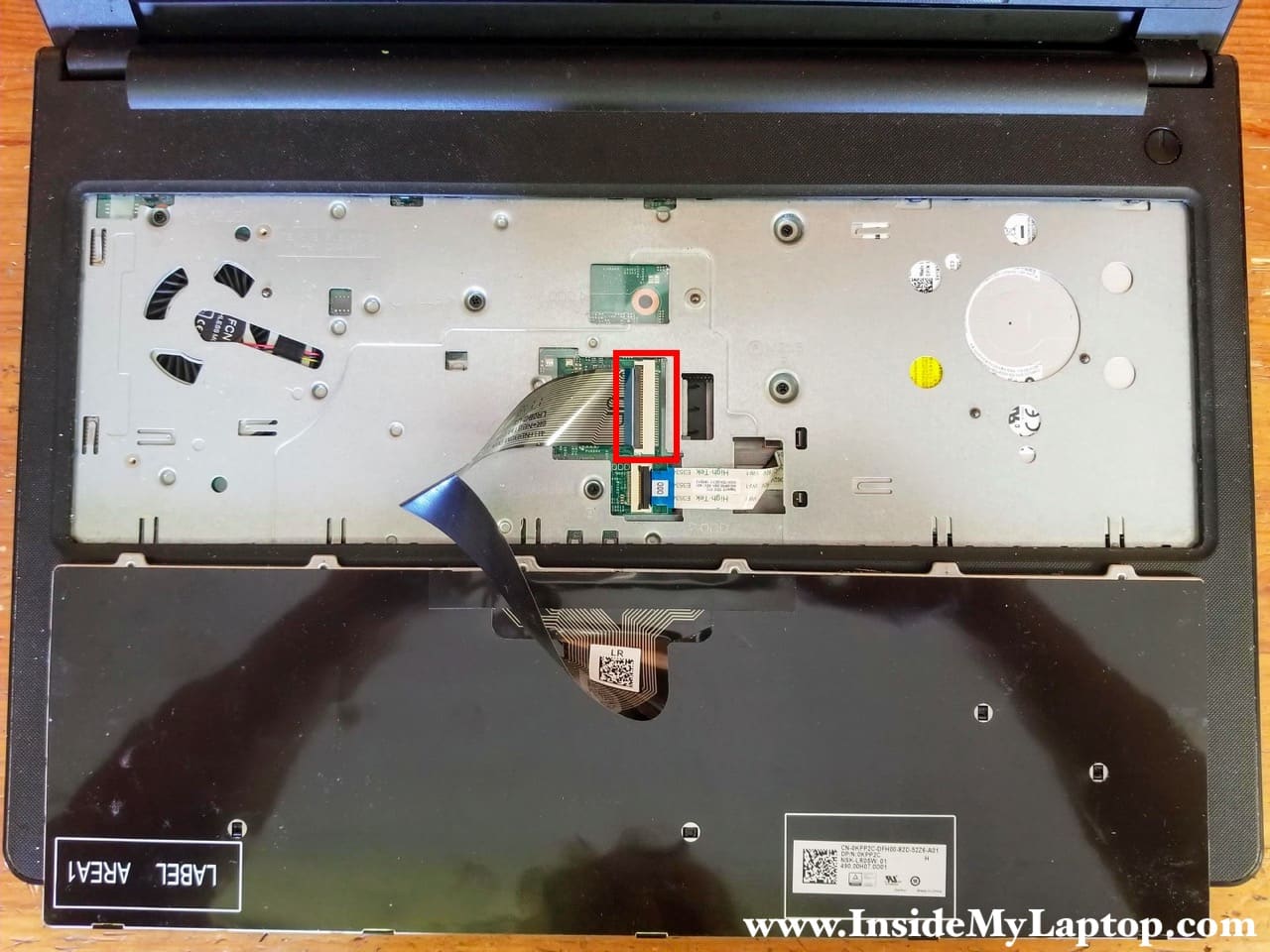
Unlock the connector by lifting up the locking tab (red arrow). Pull the cable out (yellow arrow).
NOTE: Do you see the word UP written on the cable? It means this side of the cable has to faced upwards during the re-assembly. I’ve seen way too many cables installed incorrectly by first time DIY-ers.
Dell Inspiron 15 3565 3567 keyboard part number: 0KPP2C.

STEP 5.
Remove five screws securing the top case.
Disconnect the optical drive cable from the motherboard.

STEP 6.
Remove one screw securing the optical drive.
Pull the drive out.

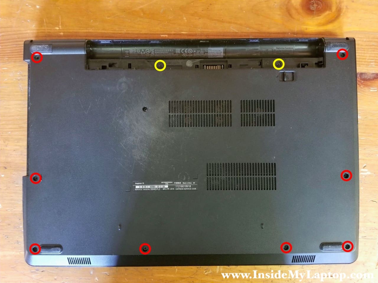
STEP 7.
Remove all screws from the bottom cover.
Two screws color-coded in yellow are different from all other screws.
STEP 8.
Don’t forget three more screws located in the optical drive bay.

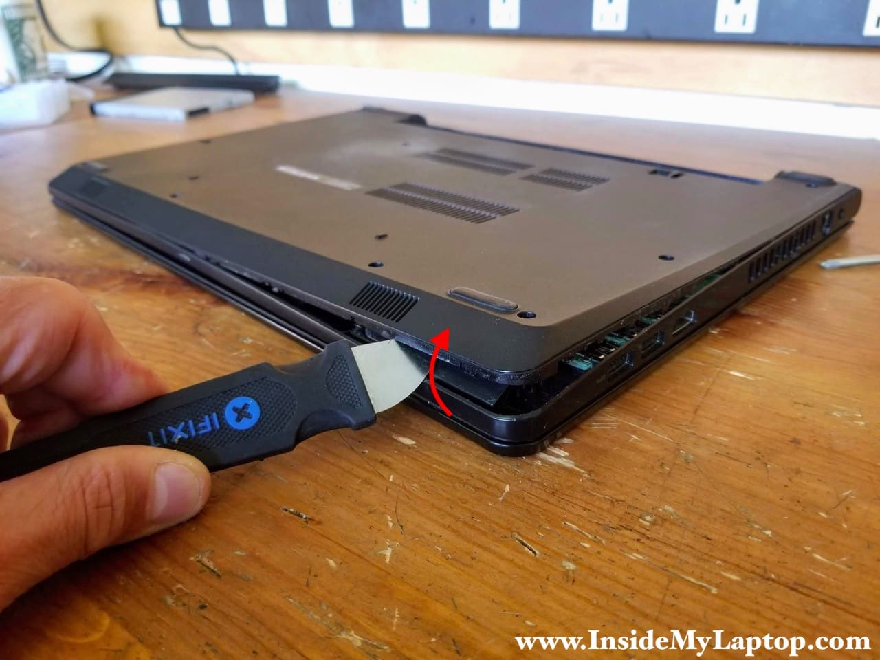
STEP 9.
Separate the bottom cover from the rest of the laptop.
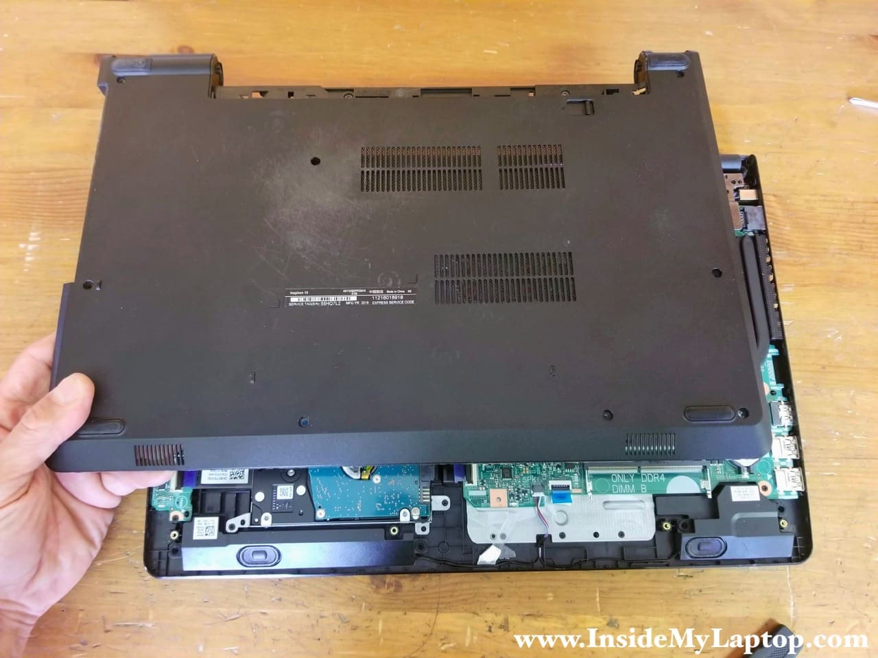
STEP 10.
Remove the bottom cover.
STEP 11.
Remove four screws attaching the hard drive bracket to the top case.
Disconnect the hard drive cable from the motherboard.
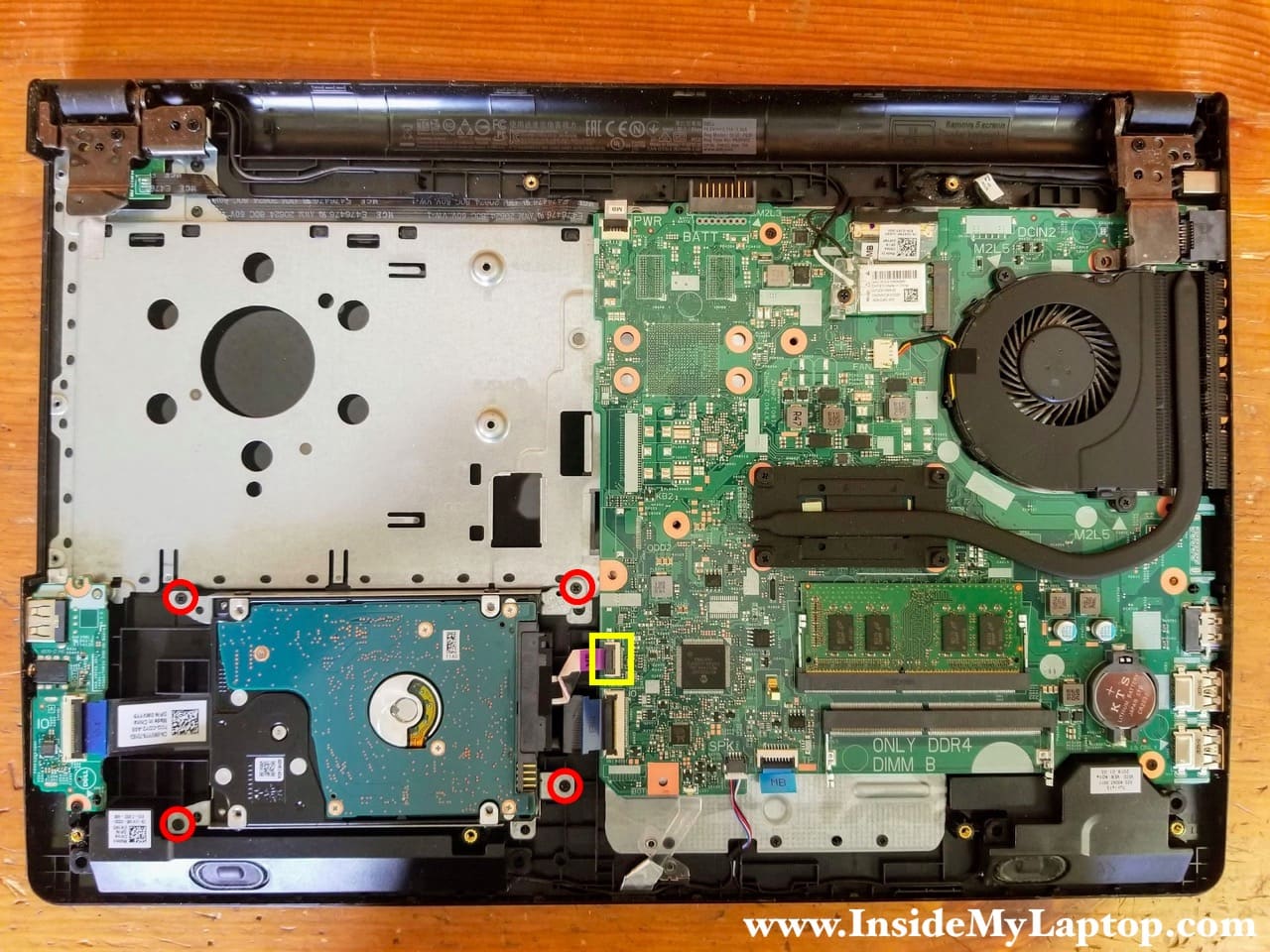
Both RAM slots accessible here. This laptop can handle up to 32GB (2x16GB) DDR4 2400/2666/3200 SODIMM RAM modules.
STEP 12.
Remove the hard drive assembly. Upgrading this drive to a 2.5″ solid state drive will improve laptop performance significantly.

STEP 13.
Remove one screw securing the Wi-Fi antenna cover.
Disconnect both antenna cables from the Wi-Fi card.

STEP 14.
Remove the wireless card.

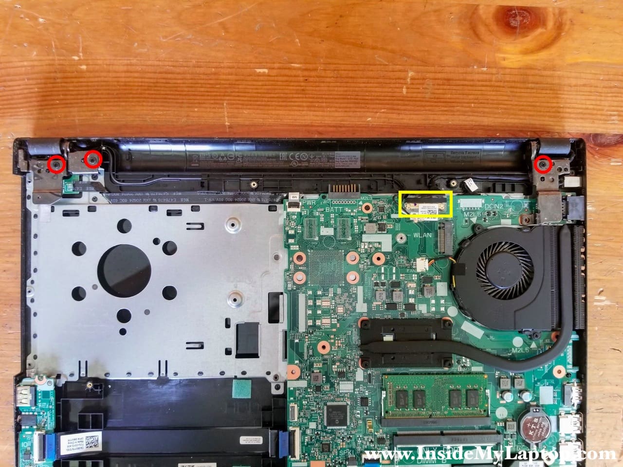
STEP 15.
Remove three screws securing the display hinges and disconnect the video cable from the motherboard.
STEP 16.
Open up both display hinges as it shown on the following picture.
Unroute the display cable and both Wi-Fi antennas.
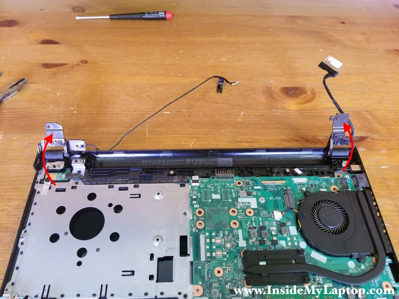
STEP 17.
Now you can separate the palmrest assembly from the display panel.

I’m not going to remove the LCD screen in this tutorial but it’s pretty much a straight forward procedure.
The LCD screen can be removed after you remove the front bezel. There are only 4 screws securing the screen to the display back cover.
Update: I just posted step-by-step instructions for removing the LCD screen on Dell Inspiron 15 3565 3567.

STEP 18.
Remove two screw securing the cooling fan and disconnect the fan cable from the motherboard.
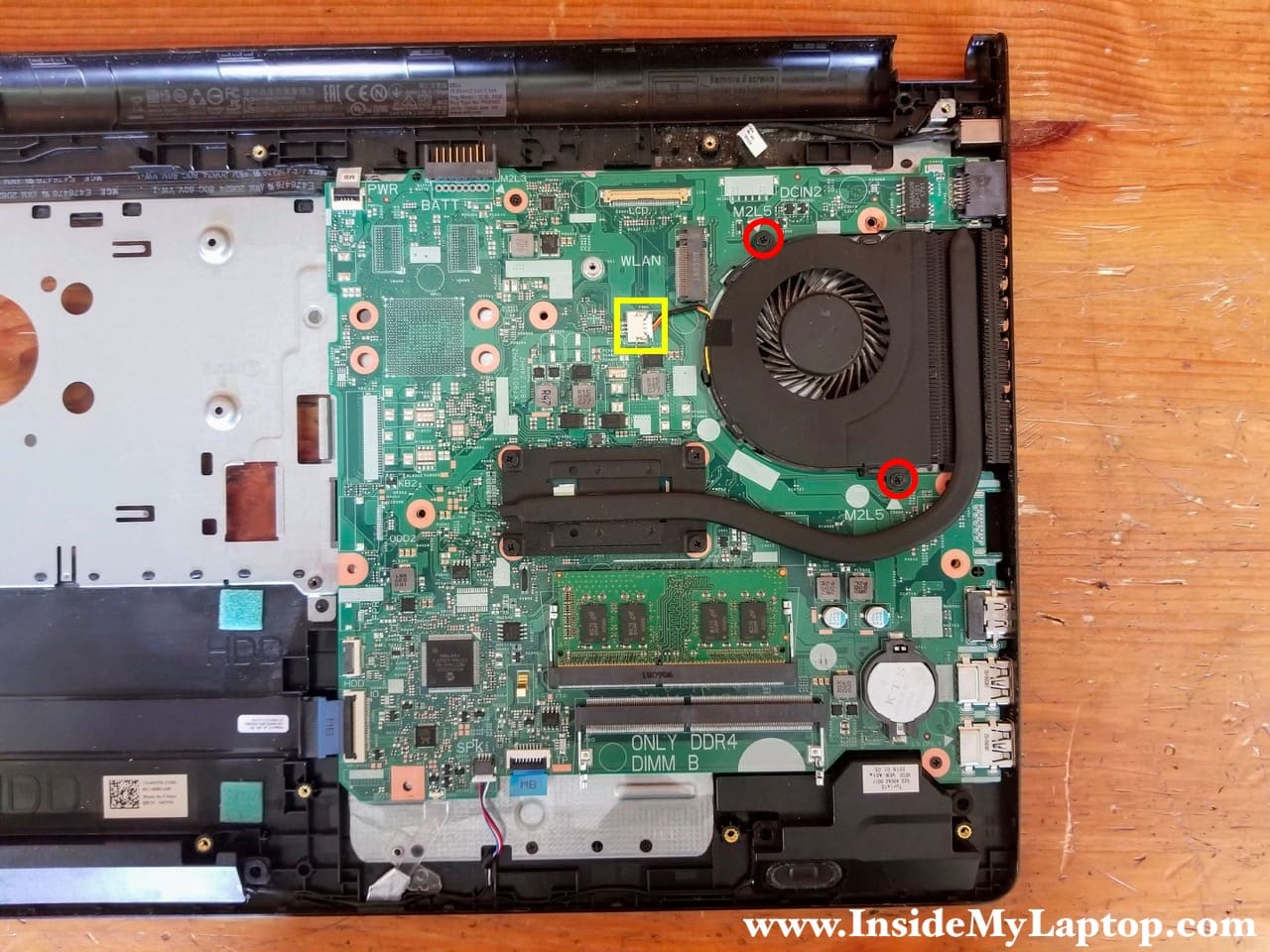
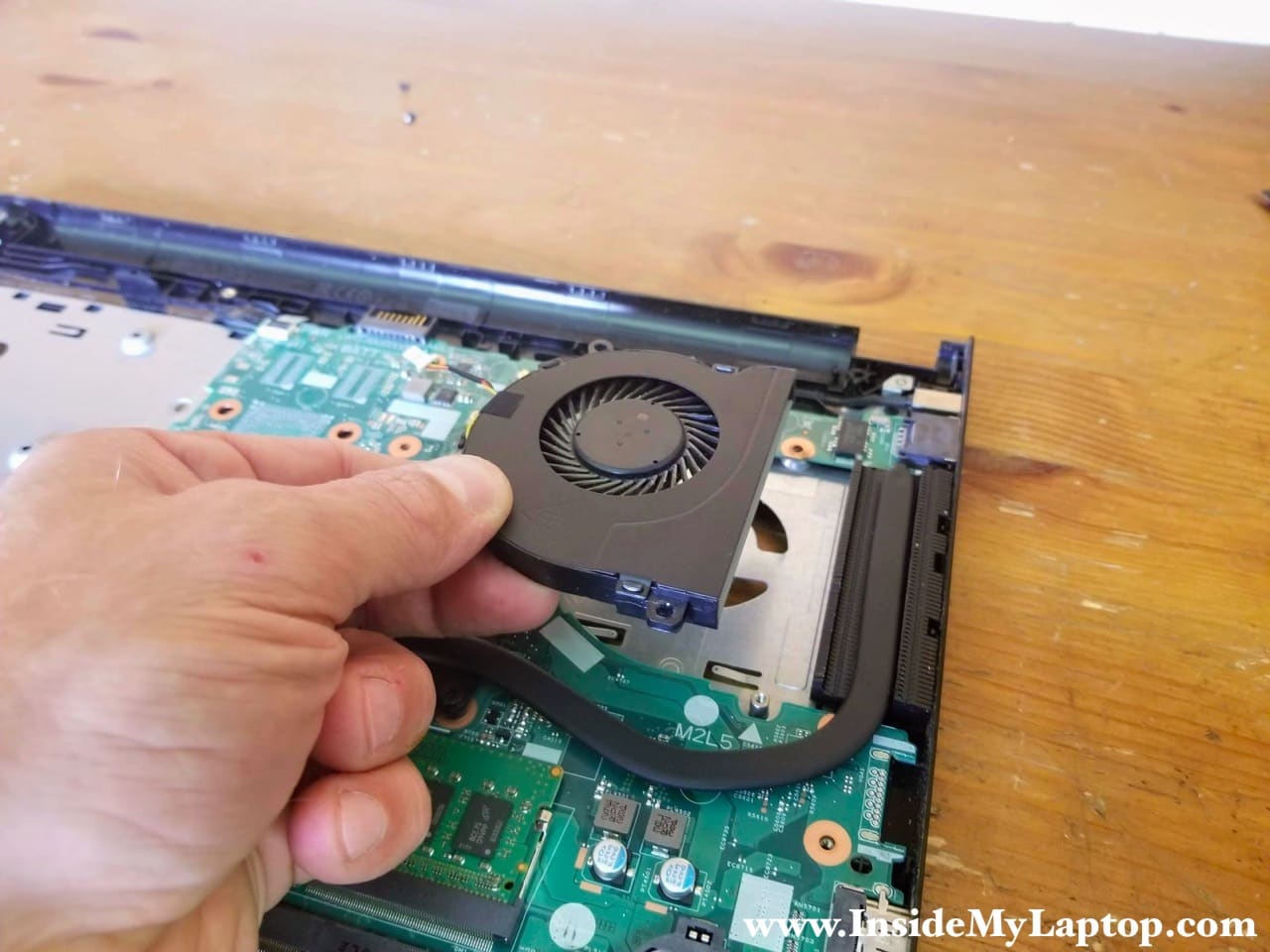
STEP 19.
Remove the fan.
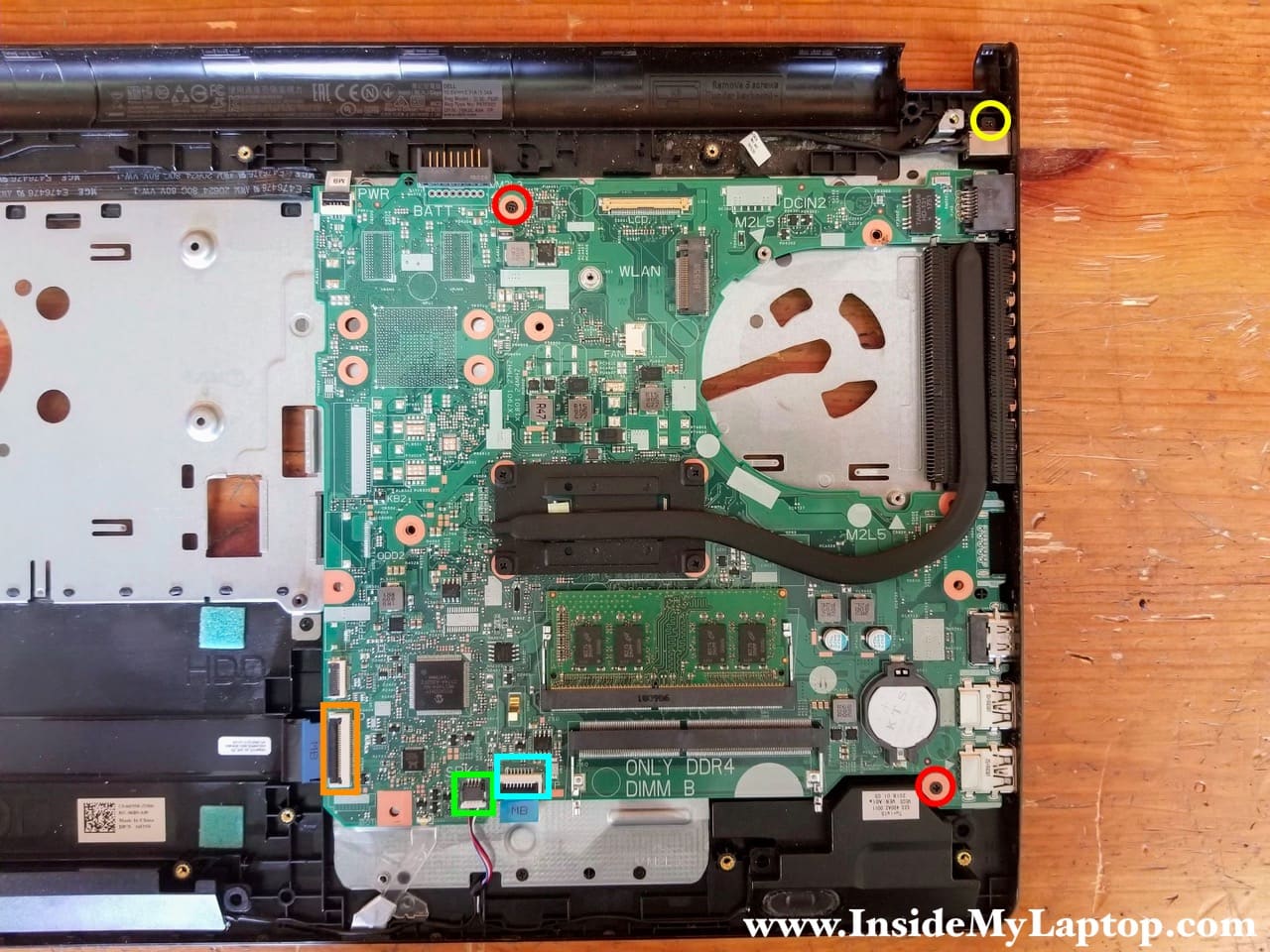
STEP 20.
Remove two screws securing the motherboard and one screw securing the DC power jack.
Disconnect the following color-coded cables:
– USB audio SD card reader board cable (orange).
– Speaker cable (green).
– Touchpad cable (blue).
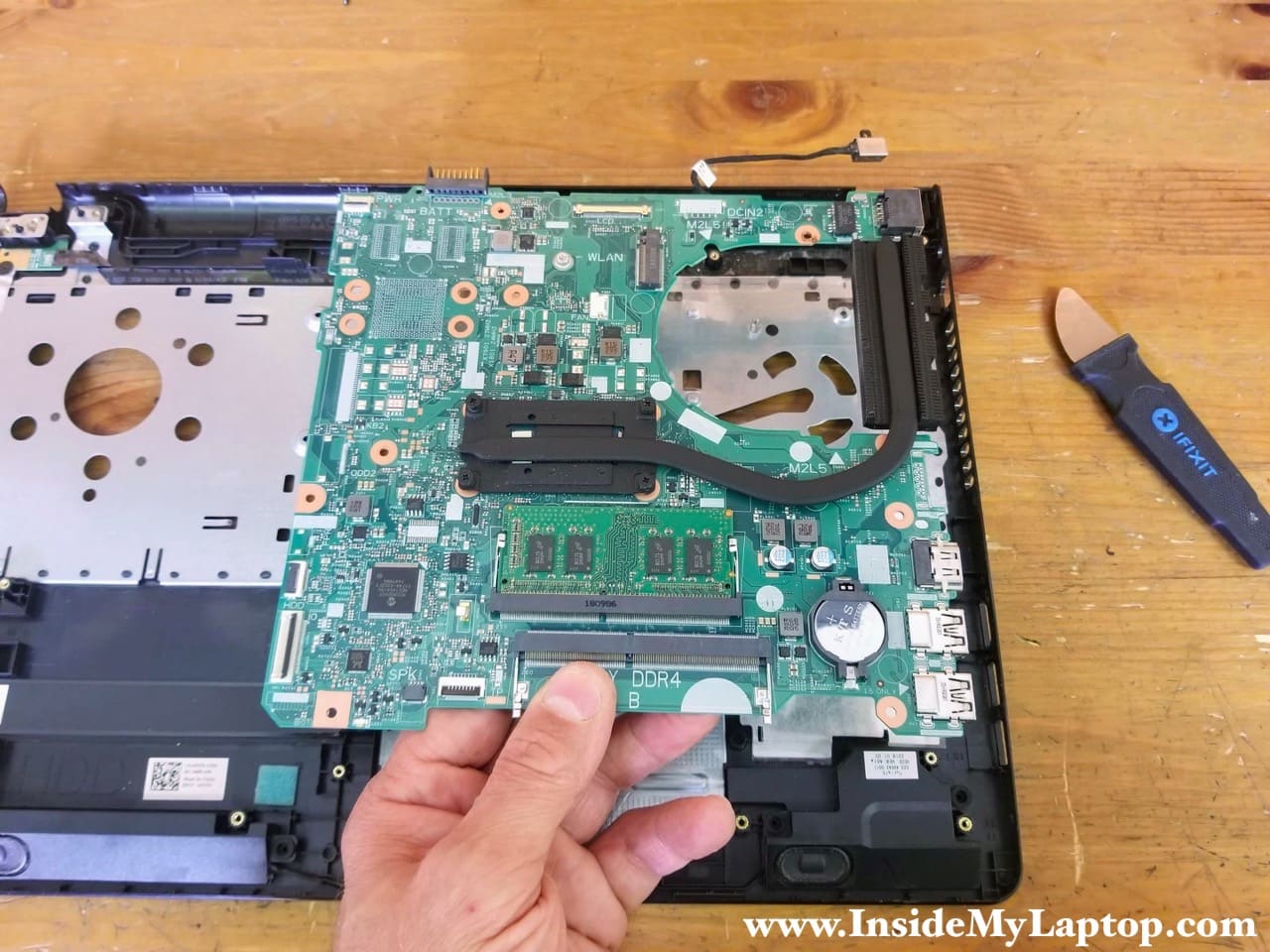
STEP 21.
Lift up and remove the motherboard.
STEP 22.
You can access and disconnect the DC power jack cable on the other side of the motherboard.

The power button board, USB audio SD card board and touchpad are removable.
