In this post I explain how to disassemble Dell Inspiron 13 7375 2-in-1 model P69G laptop.
At the end of this tutorial you can find a link to the official Dell Inspiron 13 7375 2-in-1 service manual.
How this model is different from other convertible laptops? Dell Inspiron 13 7375 motherboard has two memory slots thus both RAM modules can be removed, replaced or upgraded. Also, Dell Inspiron 13 7375 has replaceable keyboard which is not permanently attached to the top case like in many other convertible laptops.
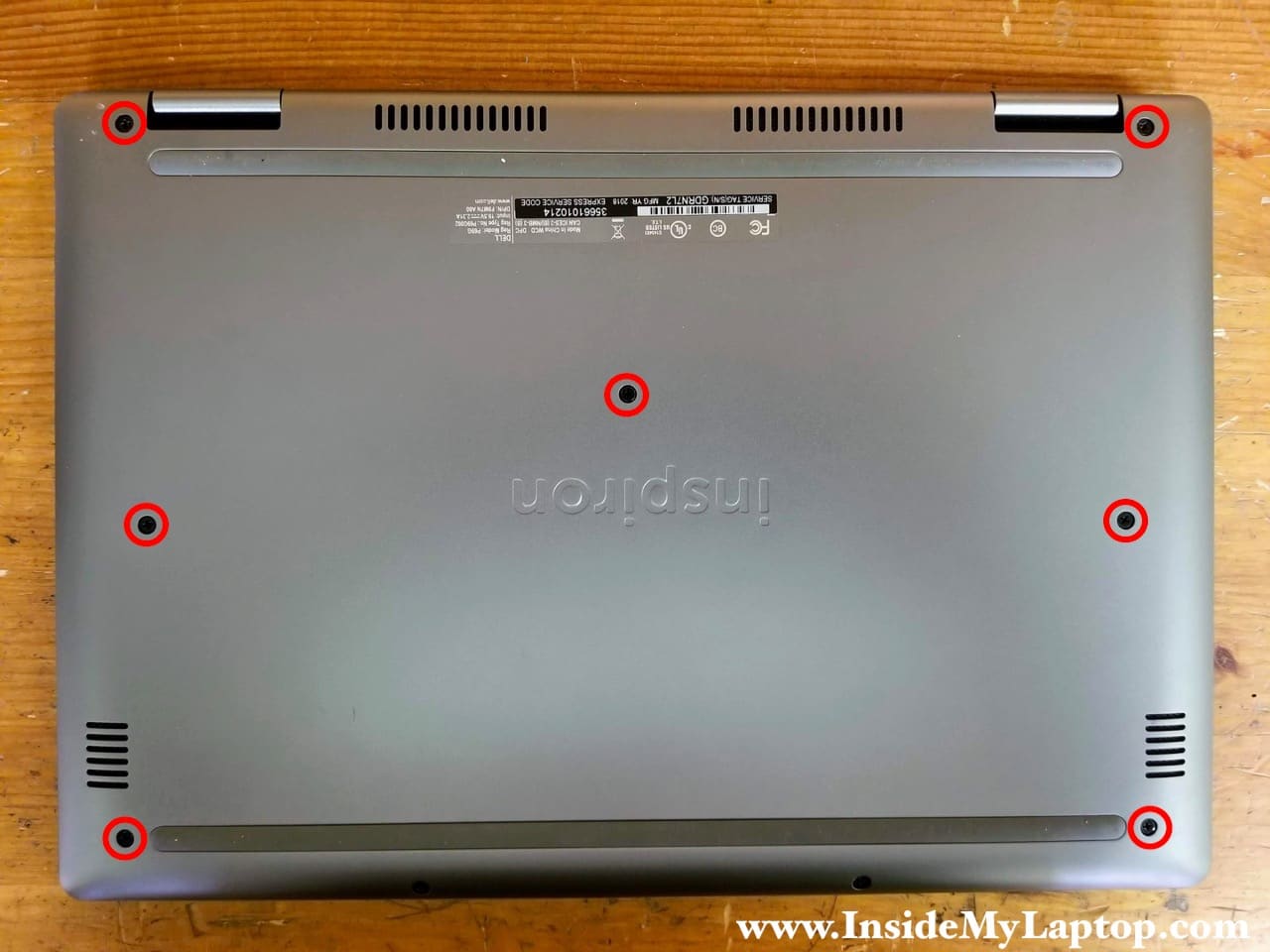
STEP 1.
Remove seven screws from the base cover.
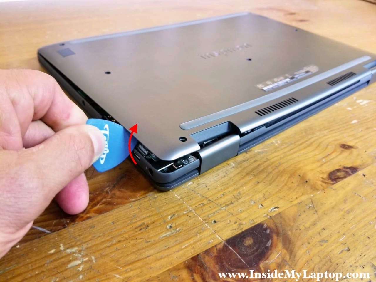
STEP 2.
Using a thin case opener tool start separating the base cover from the palmrest assembly. For me it was easier to remove the base cover when I started from the display hinge area.
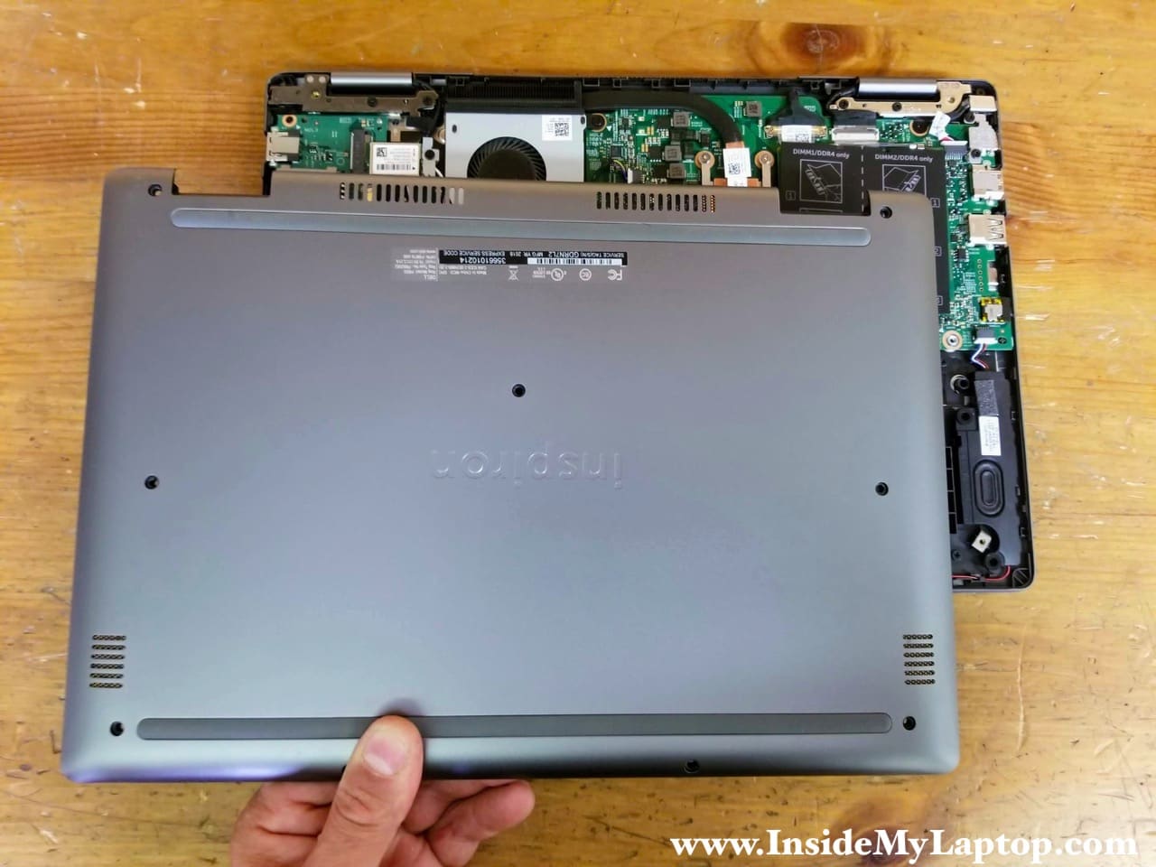
STEP 3.
Remove the base cover.
STEP 4.
Remove four screws attaching the main battery to the palmrest assembly.
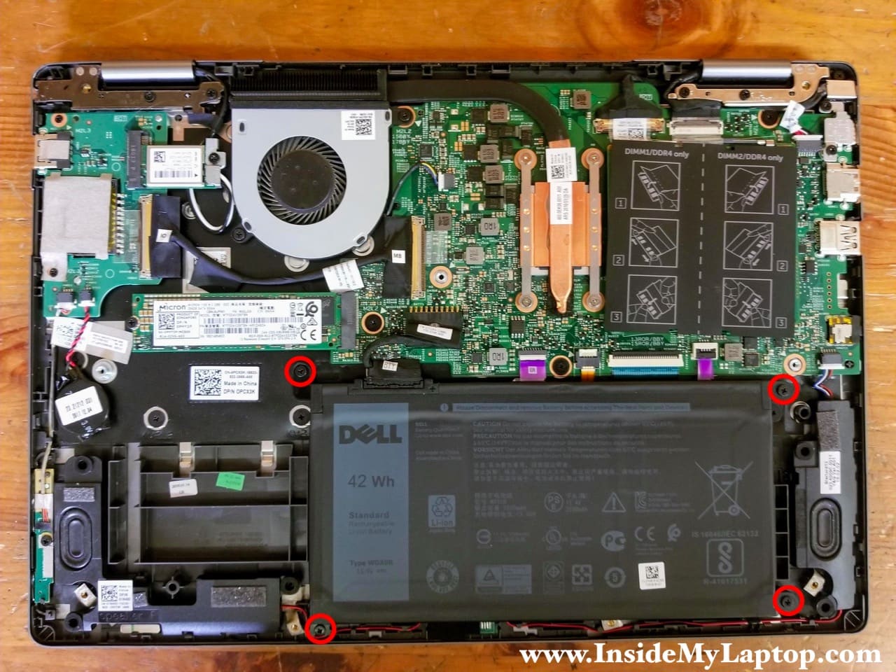
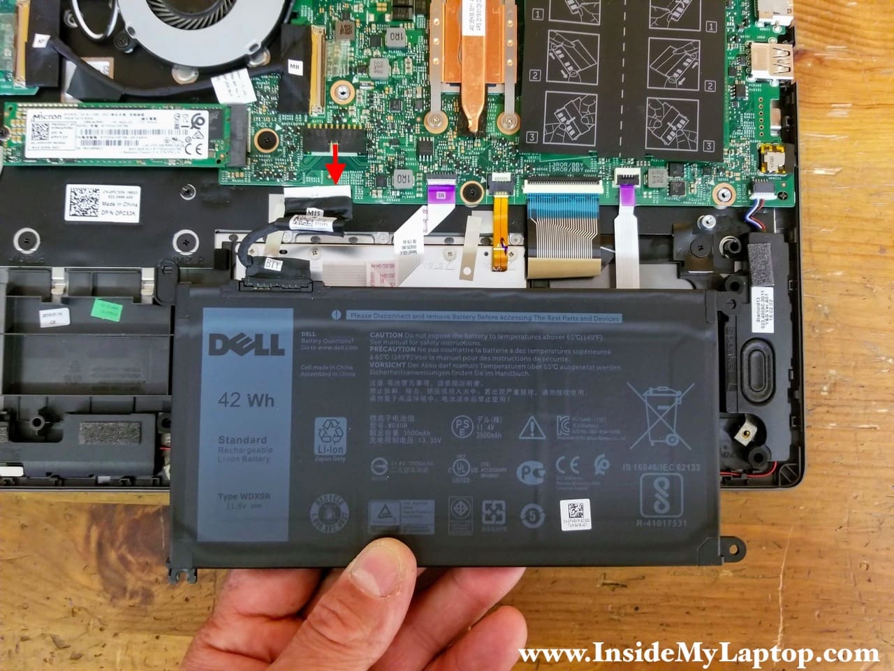
STEP 5.
Lift up the battery and disconnect it from the motherboard. Remove the battery. Replacement batteries type WDX0R.
STEP 6.
Remove one screw securing the solid state drive. Pull the solid state drive out of the slot. This is m.2 SATA III solid state drive (type 2280).

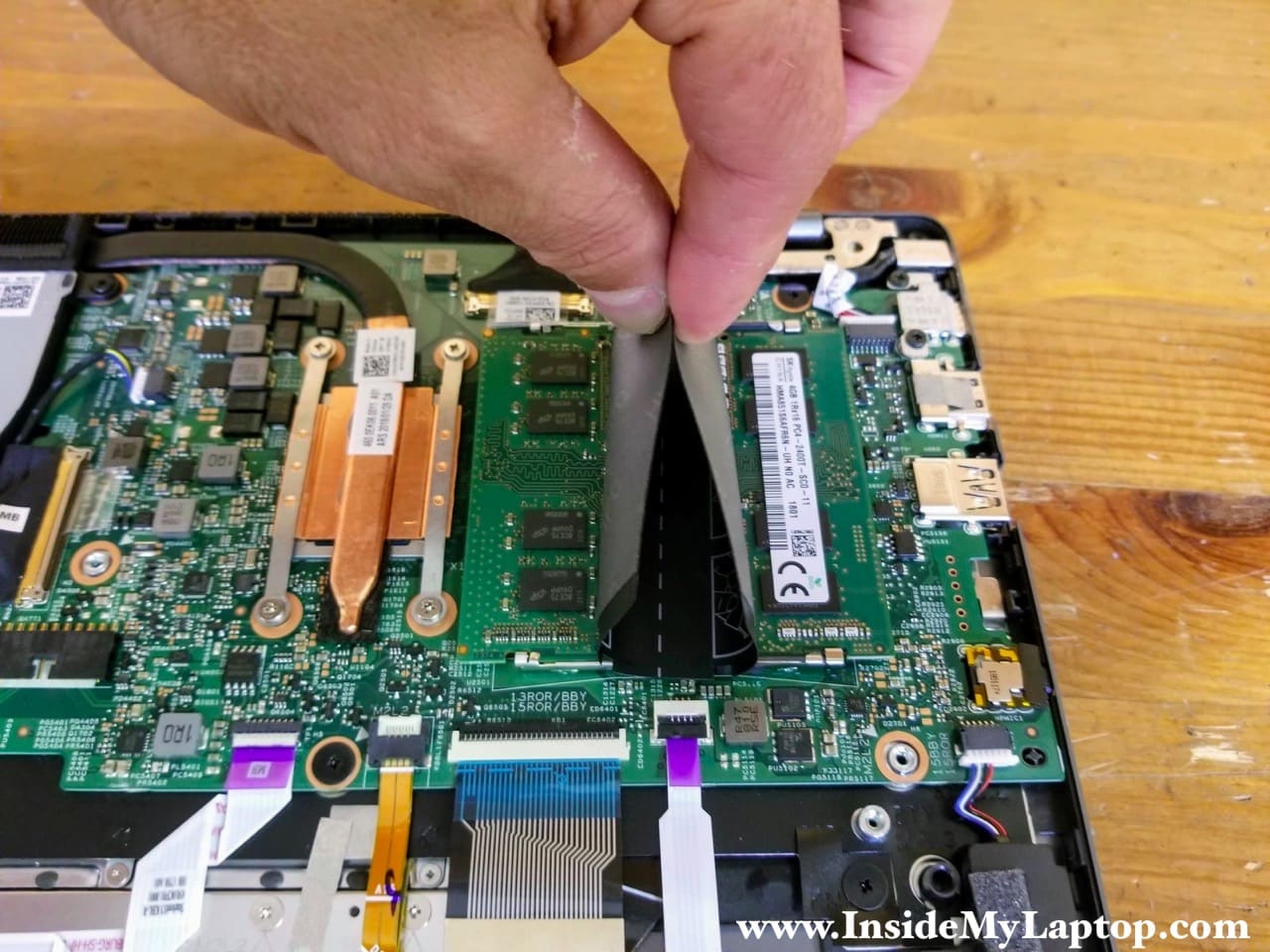
STEP 7.
In Dell Inspiron 13 7375 laptop you will find both memory (RAM) modules hidden under the black mylar cover. I will leave them connected to the motherboard but they are easily accessible for removal and replacement if necessary.
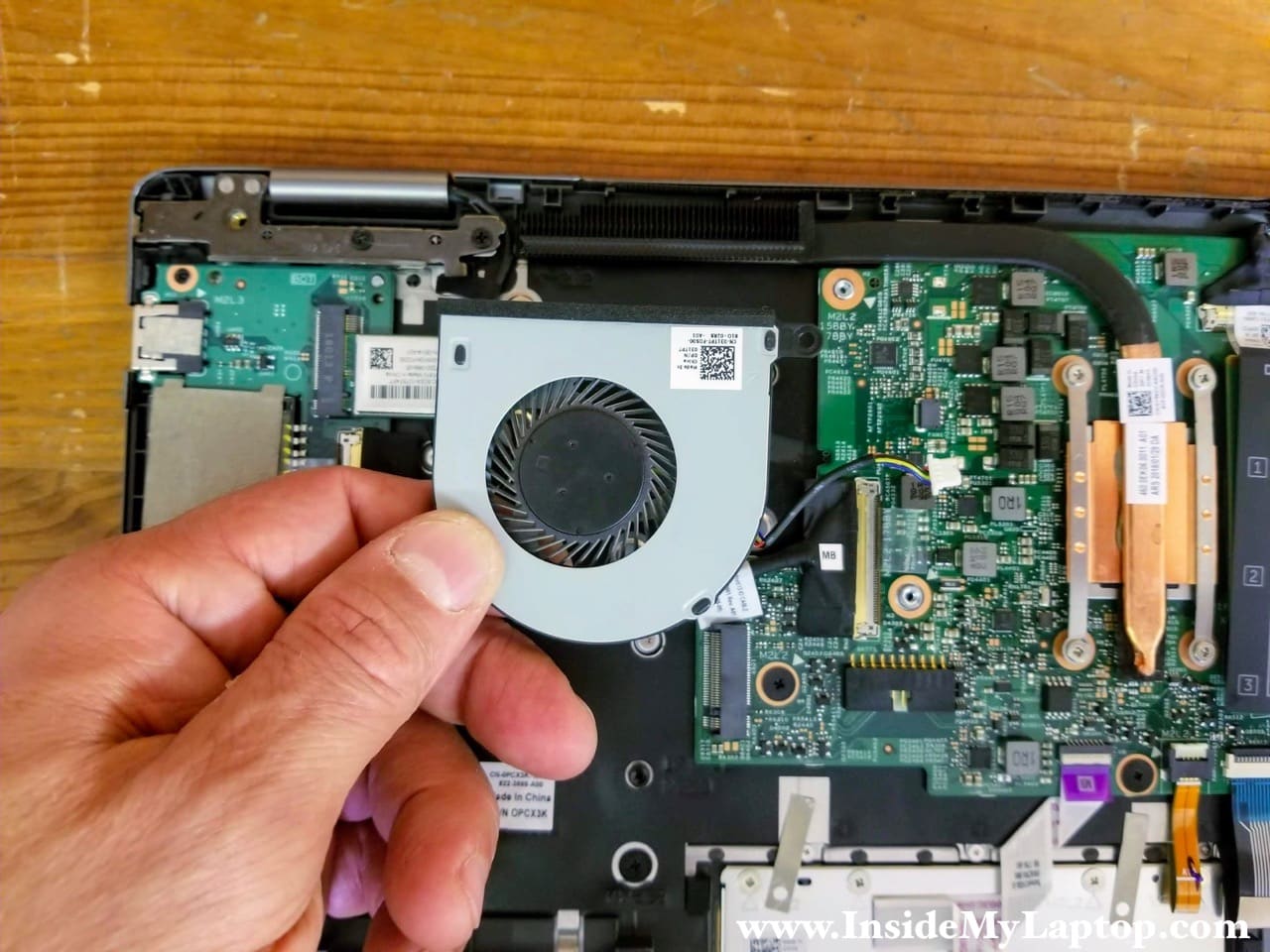
STEP 8.
Remove two screws securing the cooling fan and disconnect fan cable from the motherboard.

STEP 9.
Remove the cooling fan.
STEP 10.
Remove one screw securing the power button and volume control board. Disconnect the cable from the motherboard.
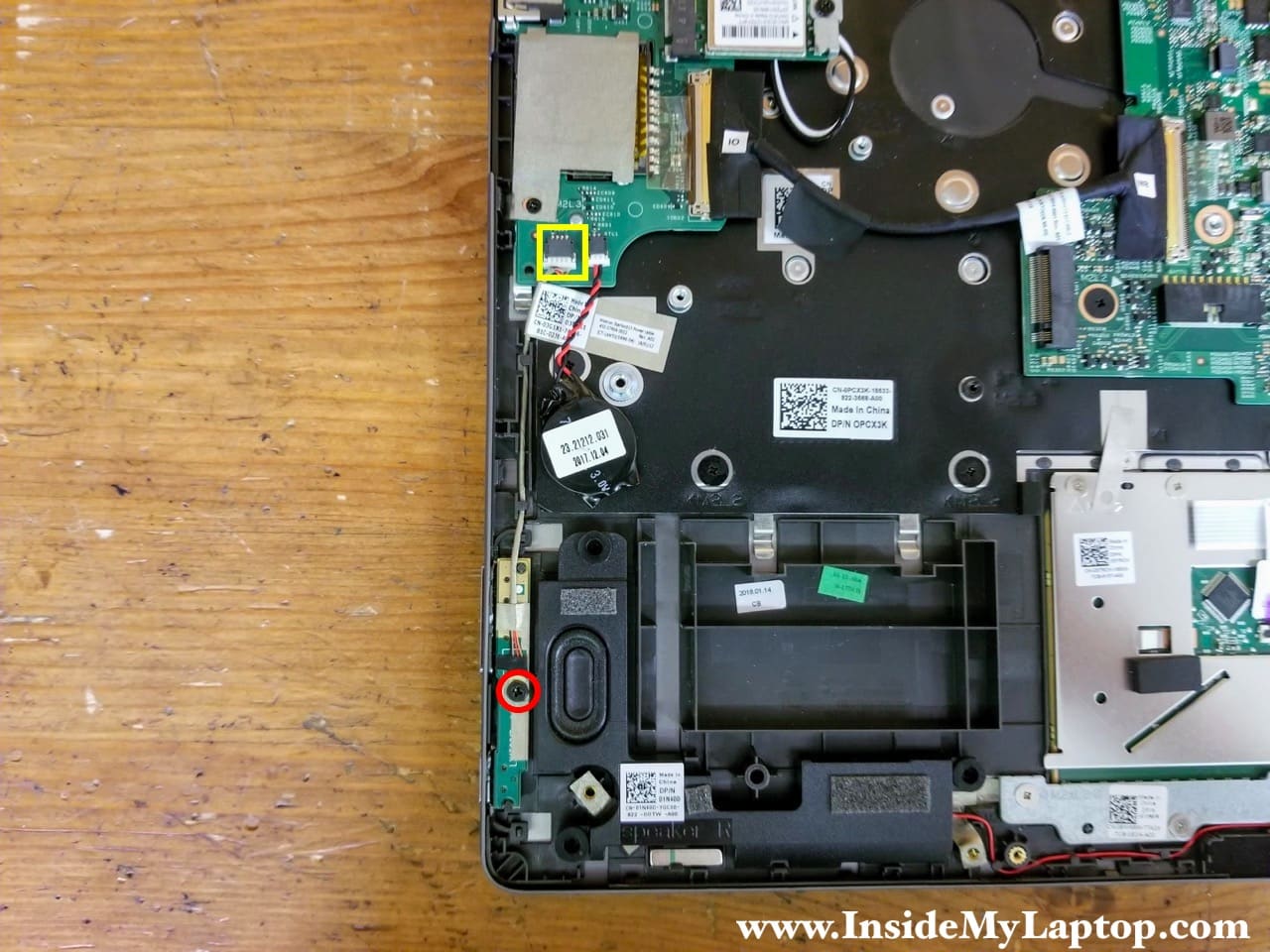
STEP 11.
Remove the power button and volume control board.

STEP 12.
Remove one screw securing the Wi-Fi antennas cover and remove the cover.
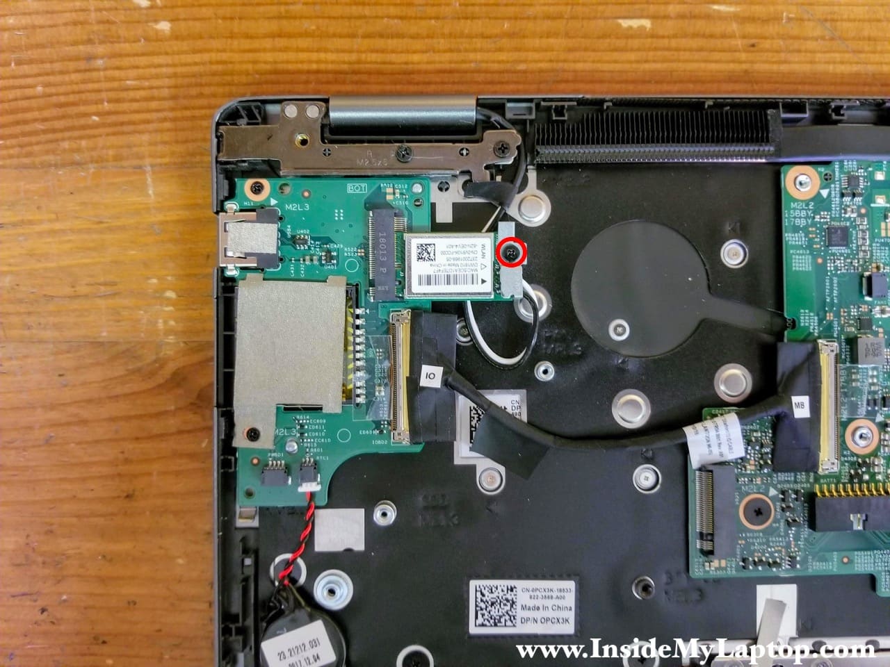
STEP 13.
Disconnect both antenna cables from the wireless card.
Pull the wireless card out of the slot.

STEP 14.
Remove two screws securing the I/O board (USB SD card reader).
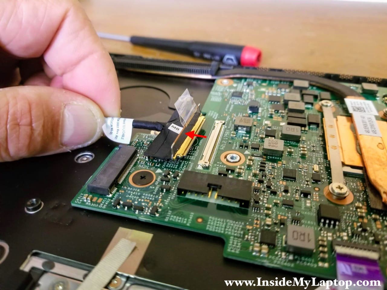
Disconnect the I/O cable from the motherboard.

Here’s how to disconnect the I/O cable.
Unlock the connector (lift up the metal bracket) and pull the cable out.
STEP 15.
Remove the I/O board.
As you see, the CMOS battery is still attached to the board.

STEP 16.
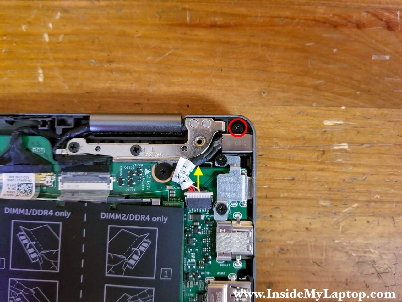
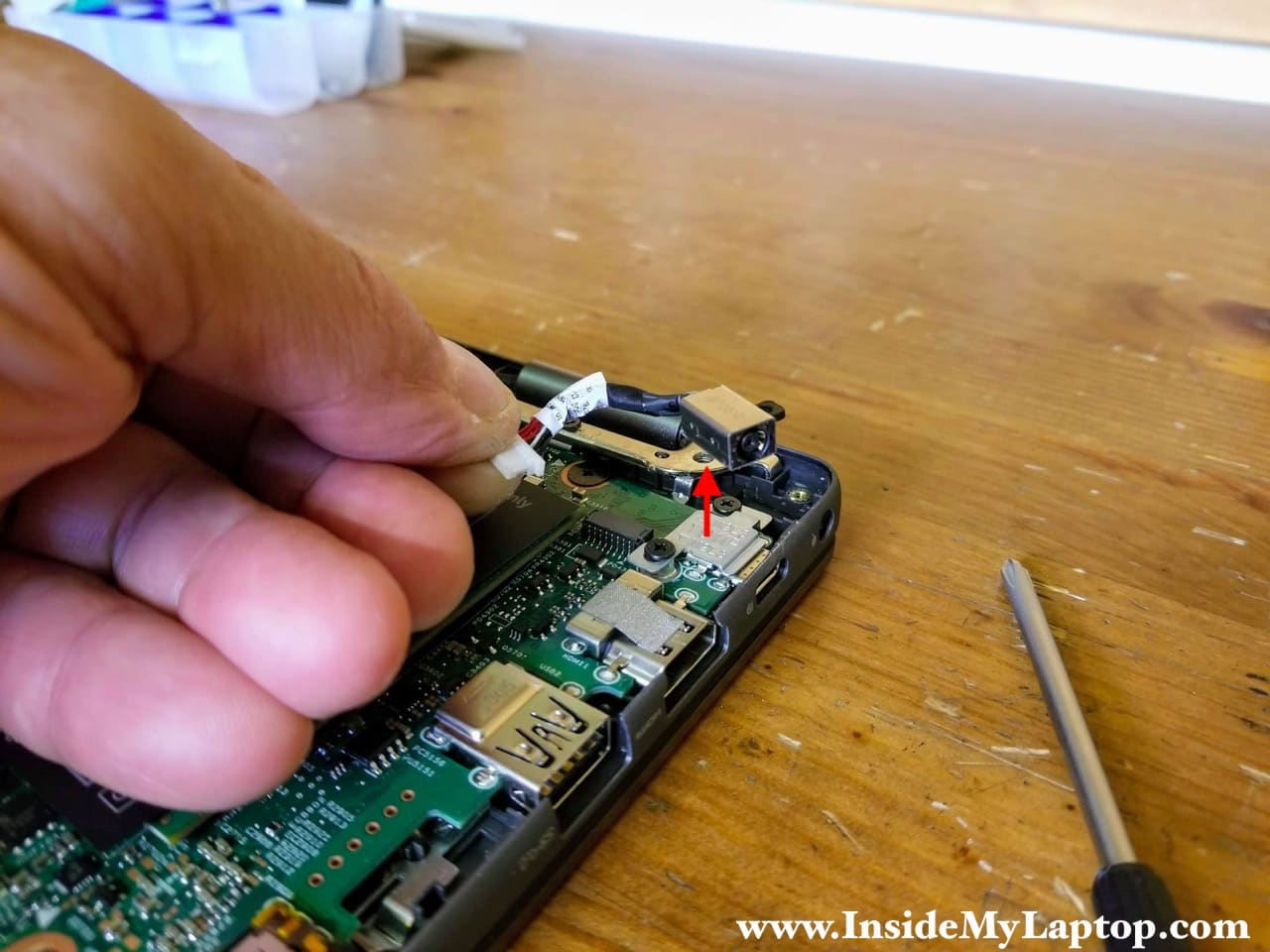
Remove one screw securing the DC power jack.
Disconnect the DC jack harness from the motherboard.
STEP 17.
Lift up and remove the DC power jack.
STEP 18.
Remove five screws securing the motherboard.
There is a metal cover over the USB-C port which also has to be removed.
Disconnect the following color-coded cables:
– Touchpad cable (orange).
– Keyboard backlight cable (yellow).
– Keyboard cable (green).
– Front light cable (light blue).
– Speaker cable (dark blue).
– Two display cables (pink).

Before you pull the cables out it’s necessary to unlock connectors.

STEP 19.
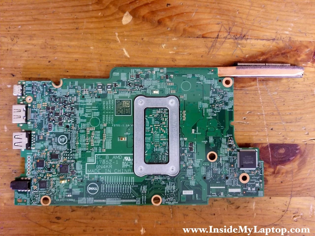
Remove the motherboard from the palmrest assembly.

Here’s a photo of the other side of the motherboard.
STEP 20.
Place the laptop upside down with the display opened up on the edge of the desk.
Remove two screws securing each display hinge.
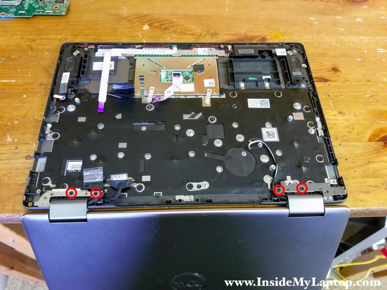
STEP 21.
Now you can separate the display panel assembly from the palmrest.

Here’s laptop palmrest with the motherboard removed.
As I mentioned earlier, the keyboard is removable. There are 28 screws securing the keyboard to the palmrest.
