In this guide I disassemble a Dell Inspiron 15 7569 or 7579 2-in-1 (model P58F) laptop. These two models are identical. It’s likely this disassembly guide will fit some other Inspiron 15 7000 2-in1 series computers.
Here are some of the Dell Inspiron 15 7569 7579 design features that make this model easily serviceable:
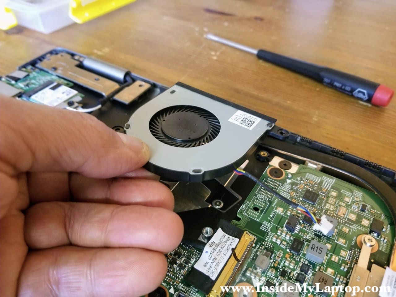
– The cooling fan can be removed and replaced without heatsink removal.
– The motherboard has two memory slots.
– The DC power jack is not soldered to the motherboard and can be easily replaced if necessary.
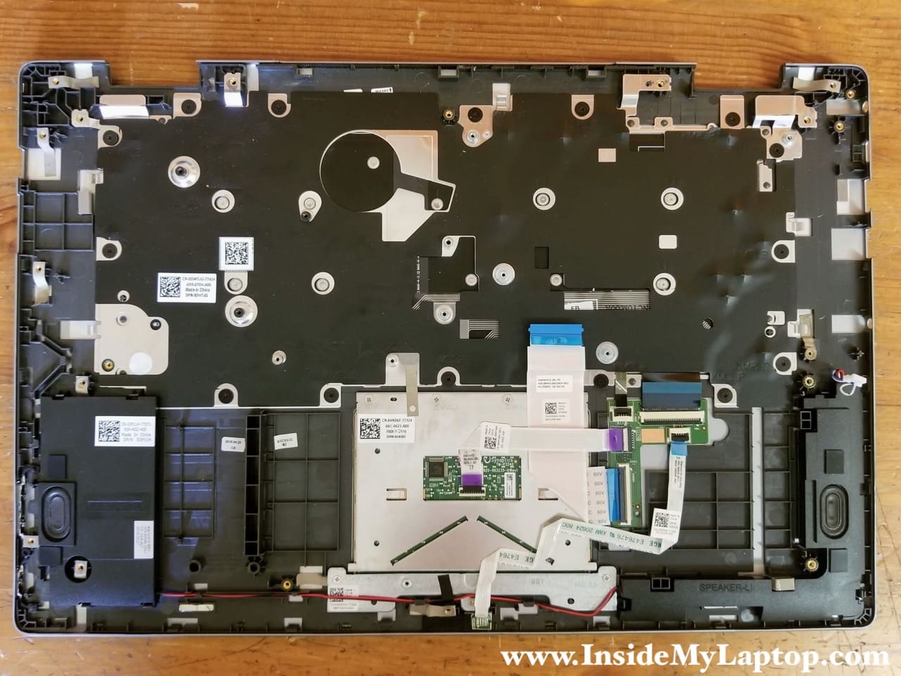
– The keyboard is not permanently attached to the top case and can be replaced separately.
For this disassembly you will need only basic tools: Phillips screwdriver #0 and fine tweezers. If you’ve never disassembled a laptop before, make sure to check out tips for beginners.
Base cover and battery removal
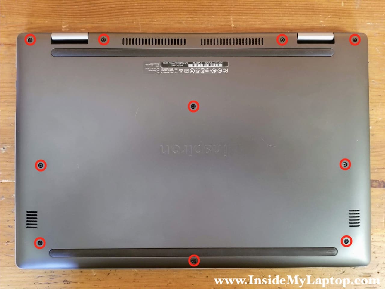
STEP 1.
Remove all screws from the base cover.
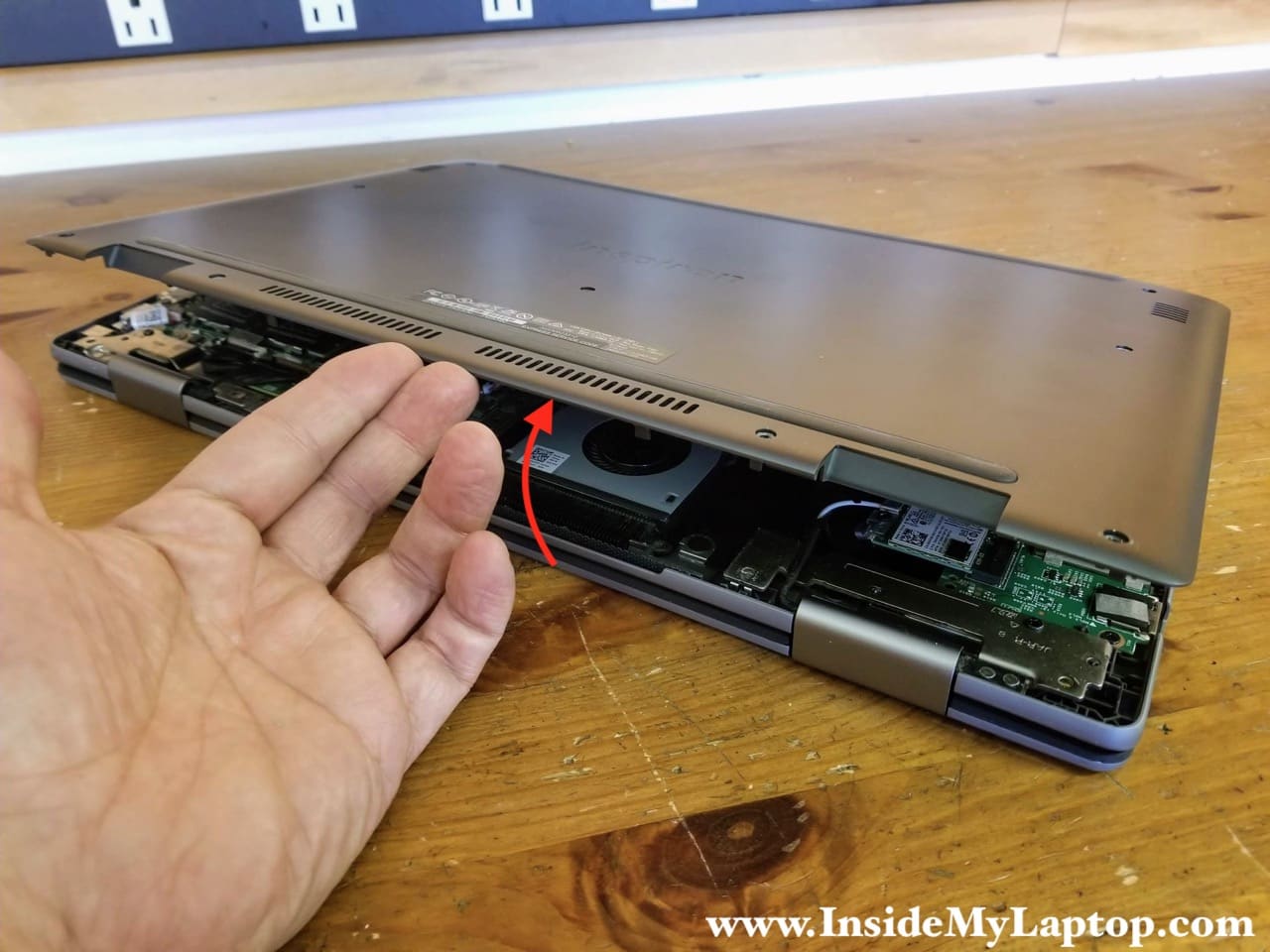
STEP 2.
Start separating the base cover from the top case assembly on the rear side of the laptop. Remove the base cover.
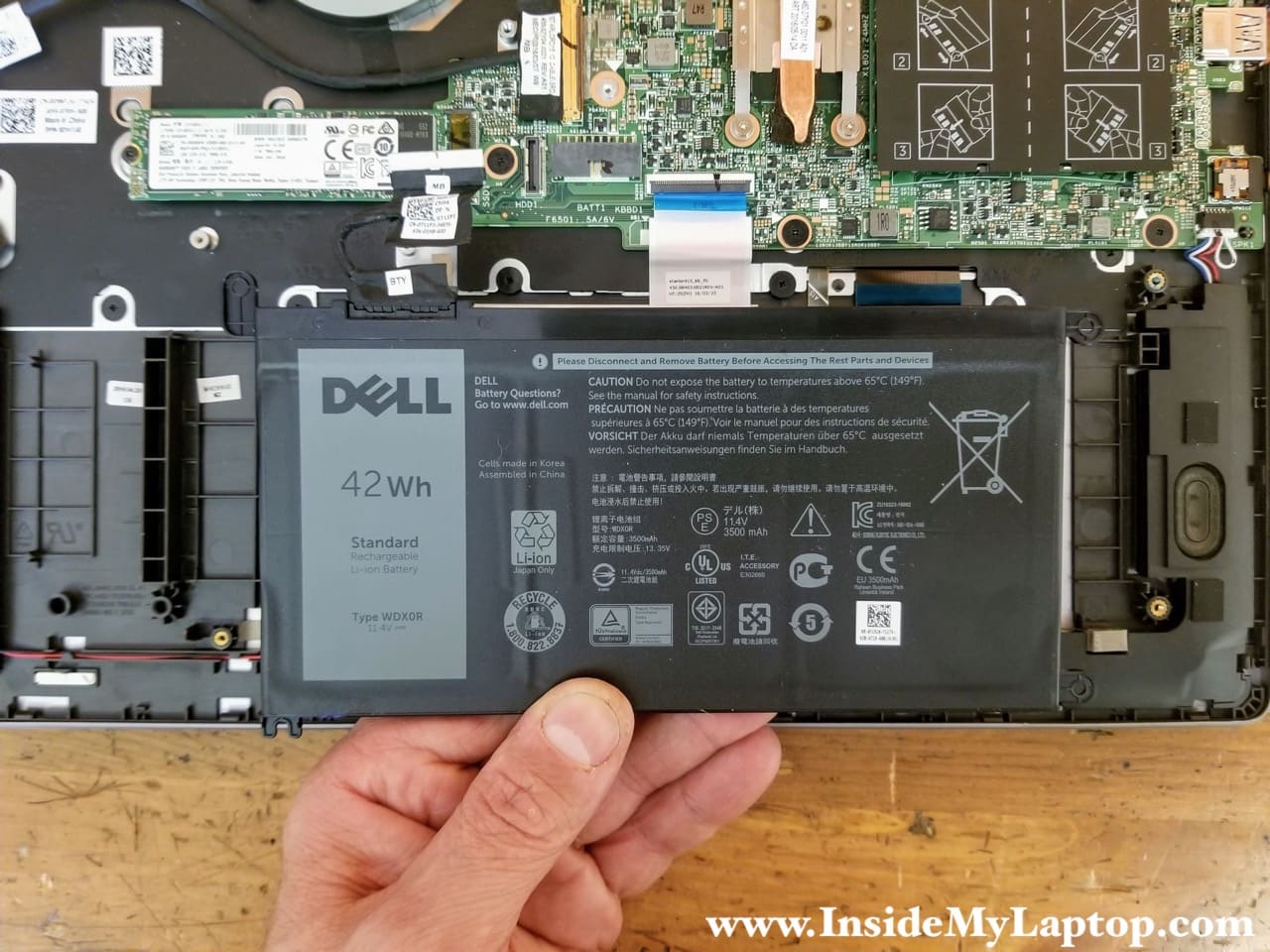
STEP 3.
Remove two screw securing the battery on the left side. Disconnect the battery cable from the motherboard.
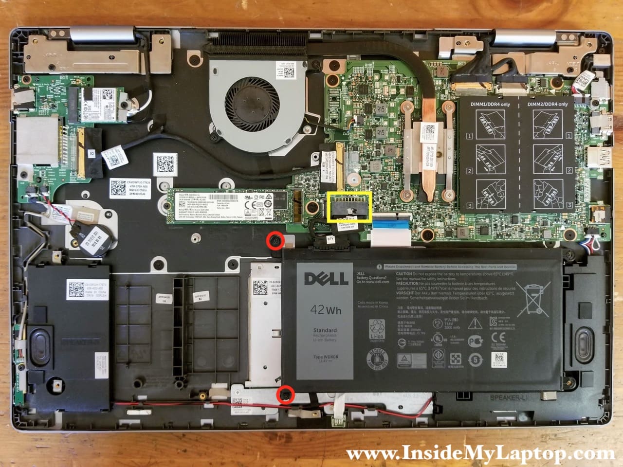
Dell Inspiron 15 7569 7579 battery type: WDX0R.
SSD, cooling fan and DC jack removal
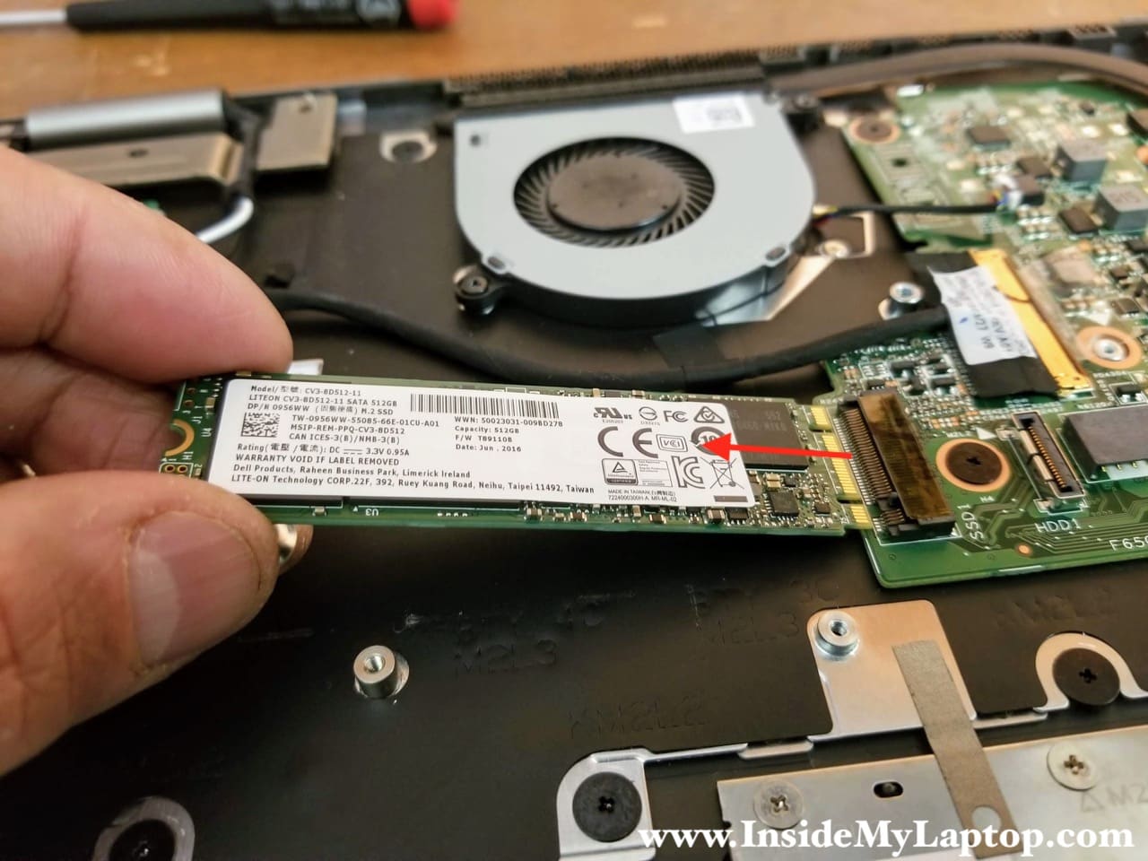
STEP 4.
Remove one screw securing the solid state drive. Pull the SSD out.
Dell Inspiron 15 7569 7579 solid state drive interface: M.2 SATA (SATA 3 – 6Gb/s).
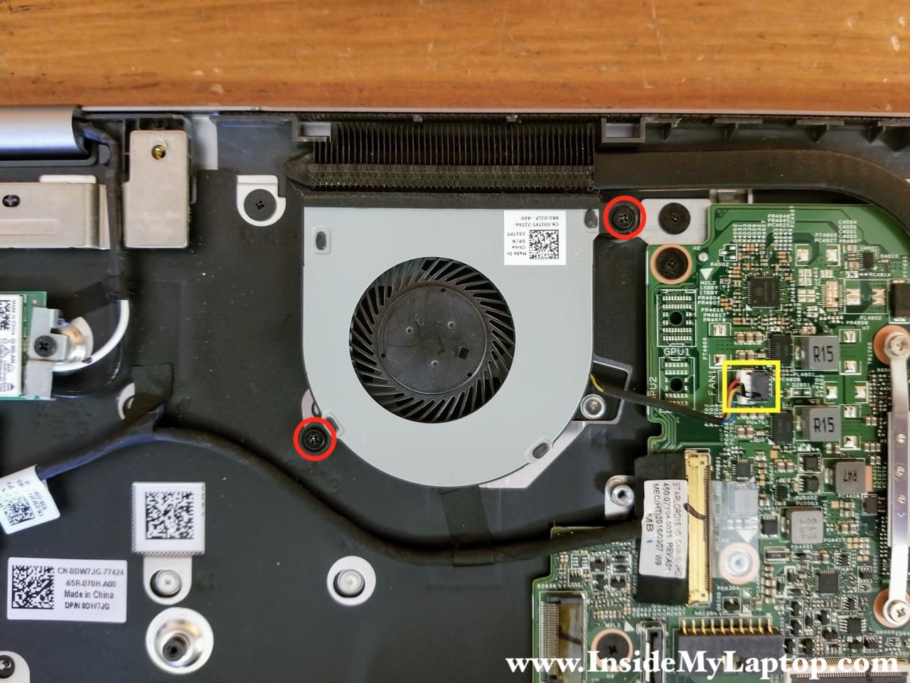
STEP 5.
Remove two screws from the cooling fan and disconnect the fan cable.
STEP 6.
Remove the fan.
STEP 7.
Remove one screw securing the DC power jack. Disconnect the DC jack cable from the motherboard.
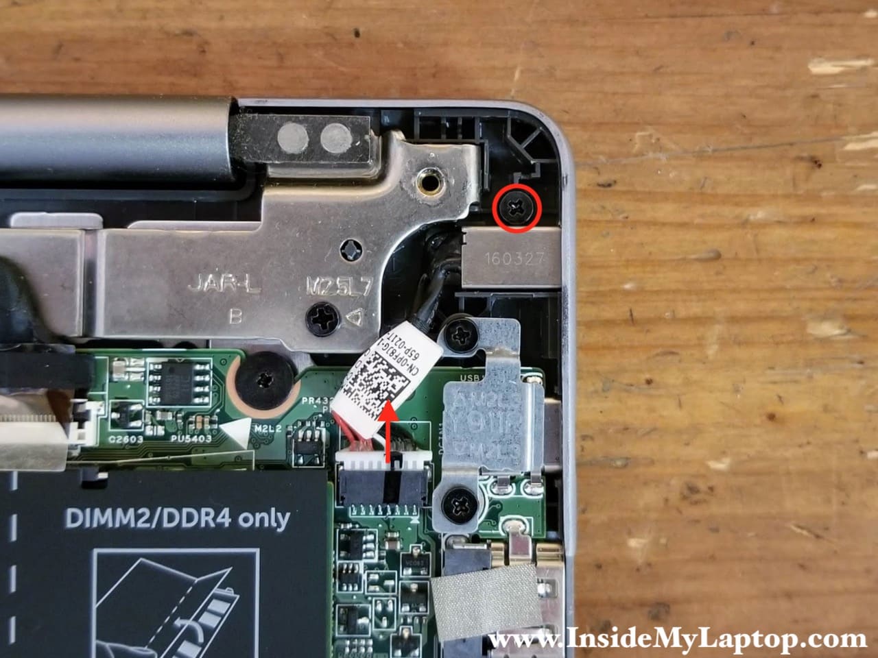
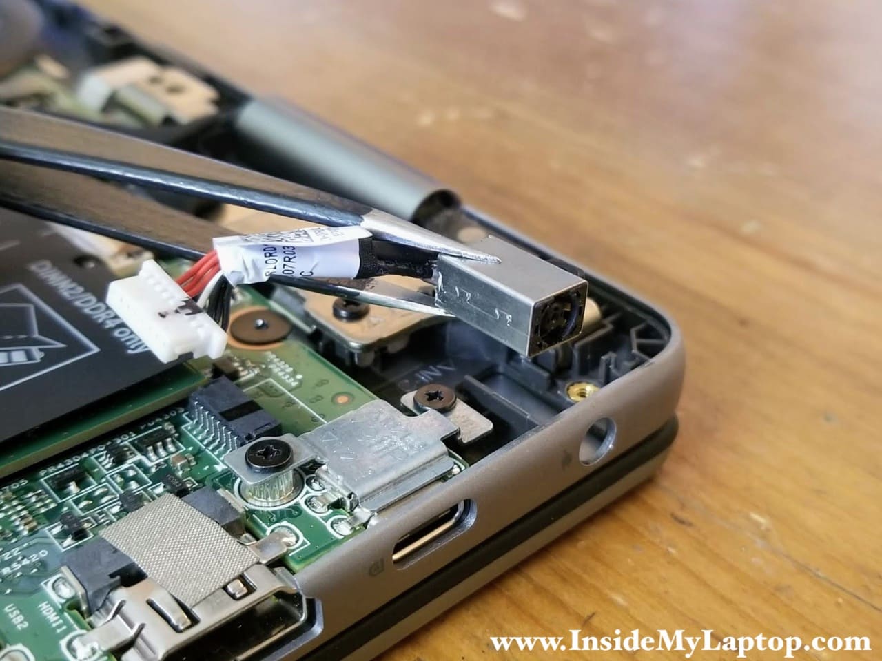
STEP 8.
Remove the DC power jack.
Wi-Fi card and power button board removal
STEP 9.
Remove one screw from the Wi-Fi card bracket. Remove the bracket.
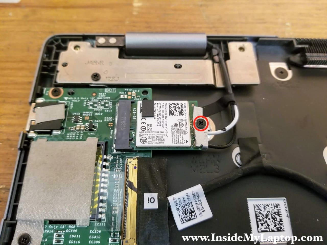
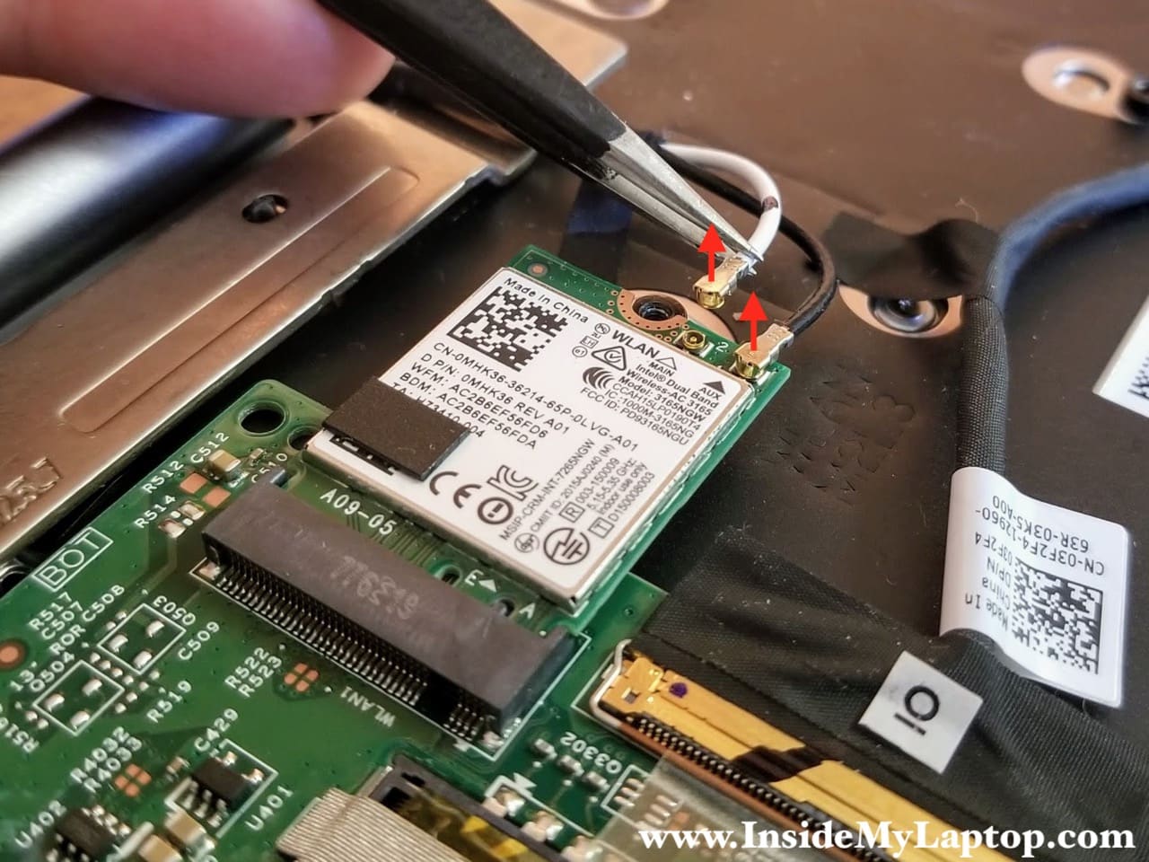
STEP 10.
Disconnect two antenna cables from the wireless card. Remove one screw securing the card. Pull the wireless card out.
STEP 11.
Remove one screw from the power button/volume control board. Disconnect the cable from the I/O board.
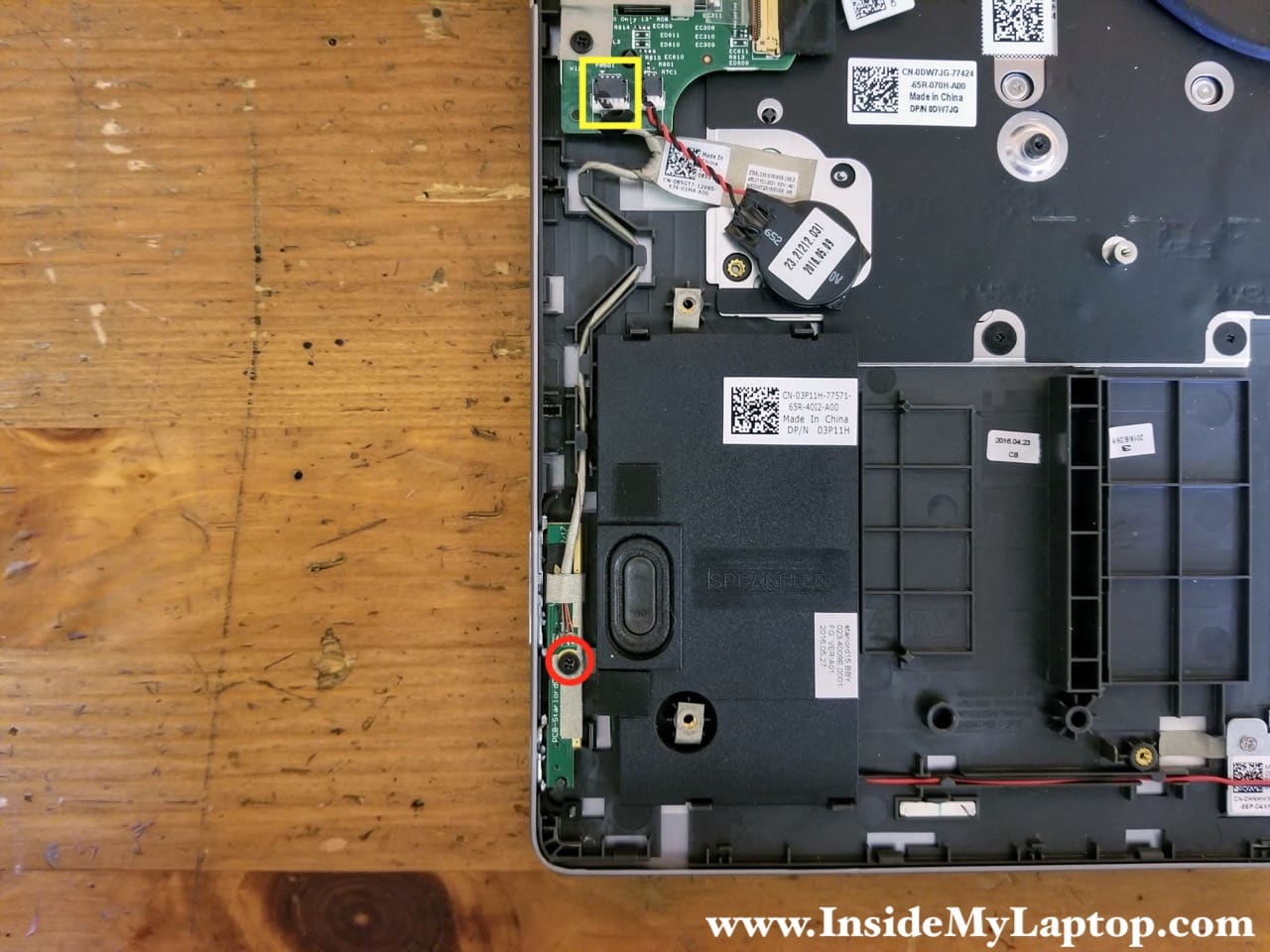
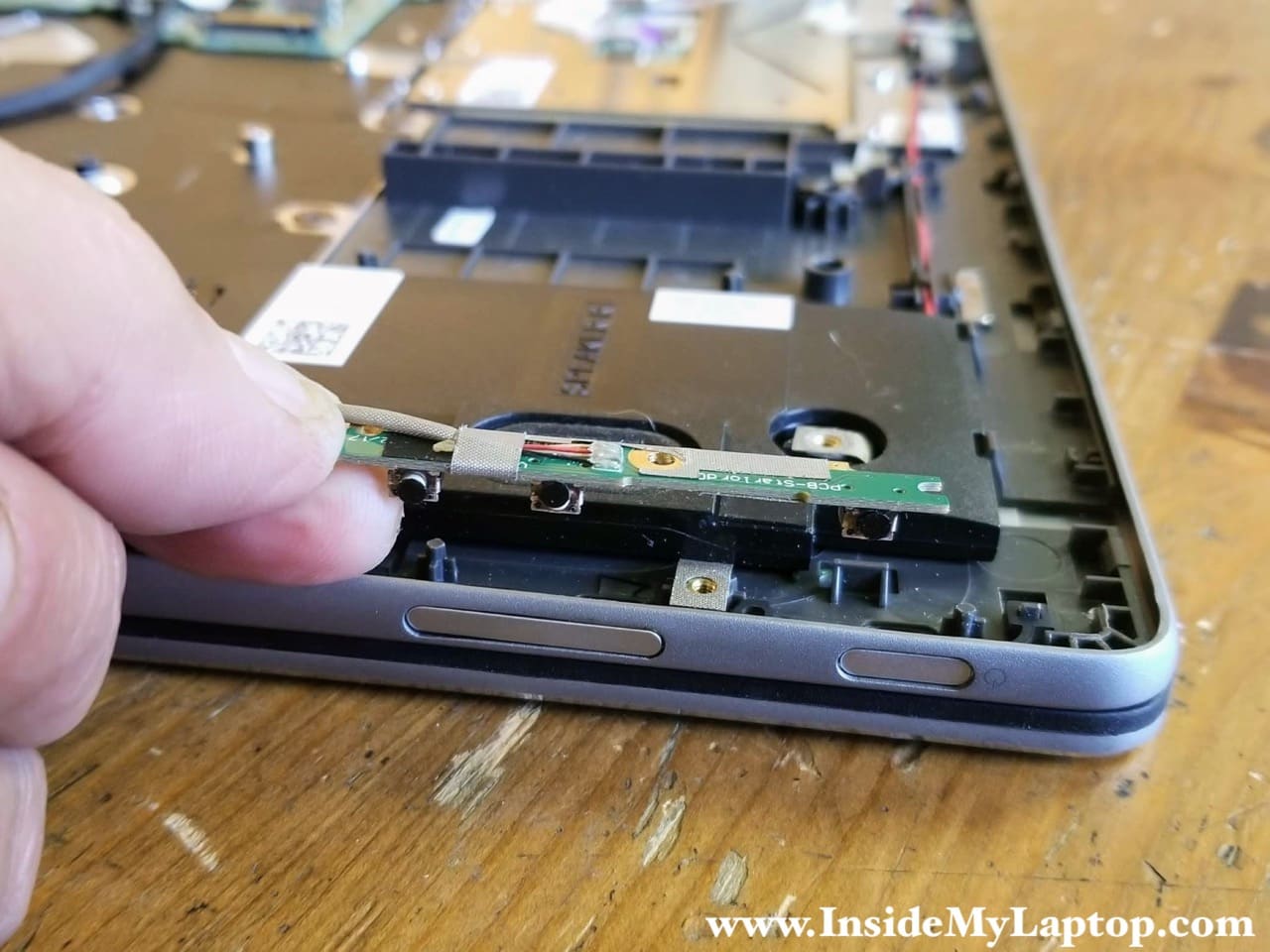
STEP 12.
Remove the power button/volume control board.
I/O board removal
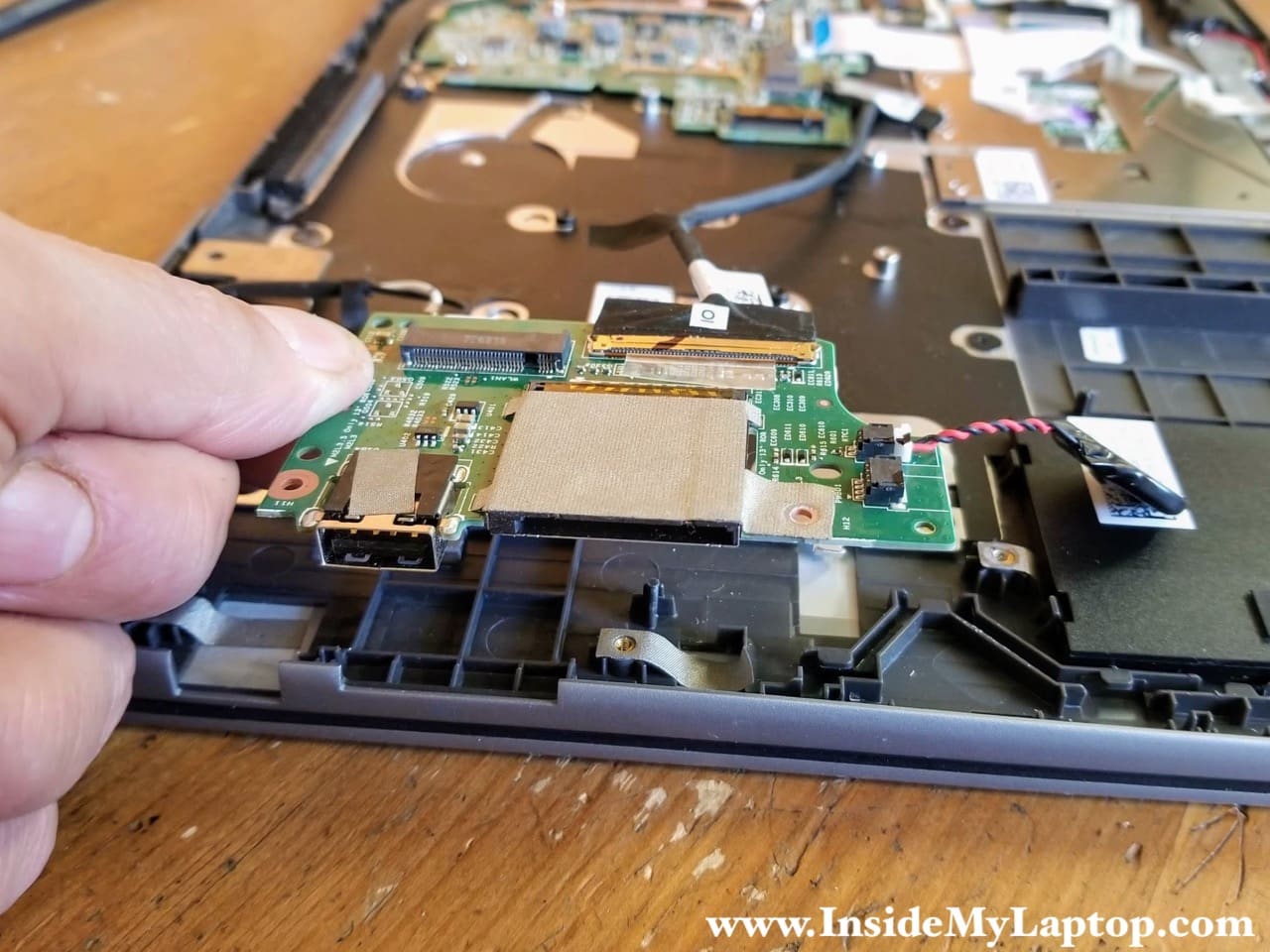
STEP 13.
Remove two screws from the USB/SD card reader board. Disconnect the I/O cable from the motherboard.
I will leave the RTC battery connected to the board. The RTC battery is glued to the top case with adhesive tape. Un-glue the battery before removing the USB/SD card reader board.
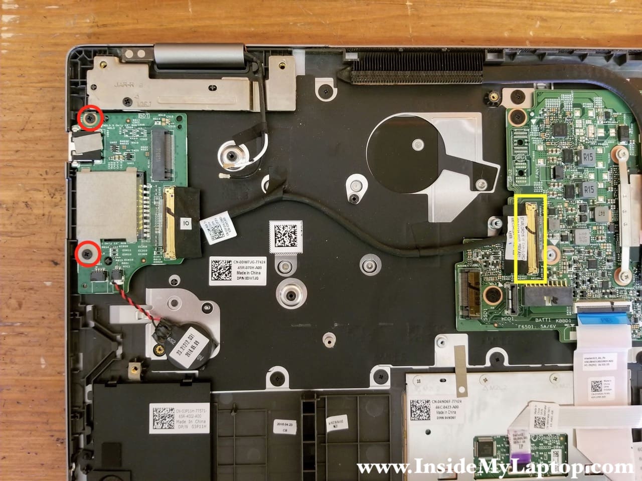
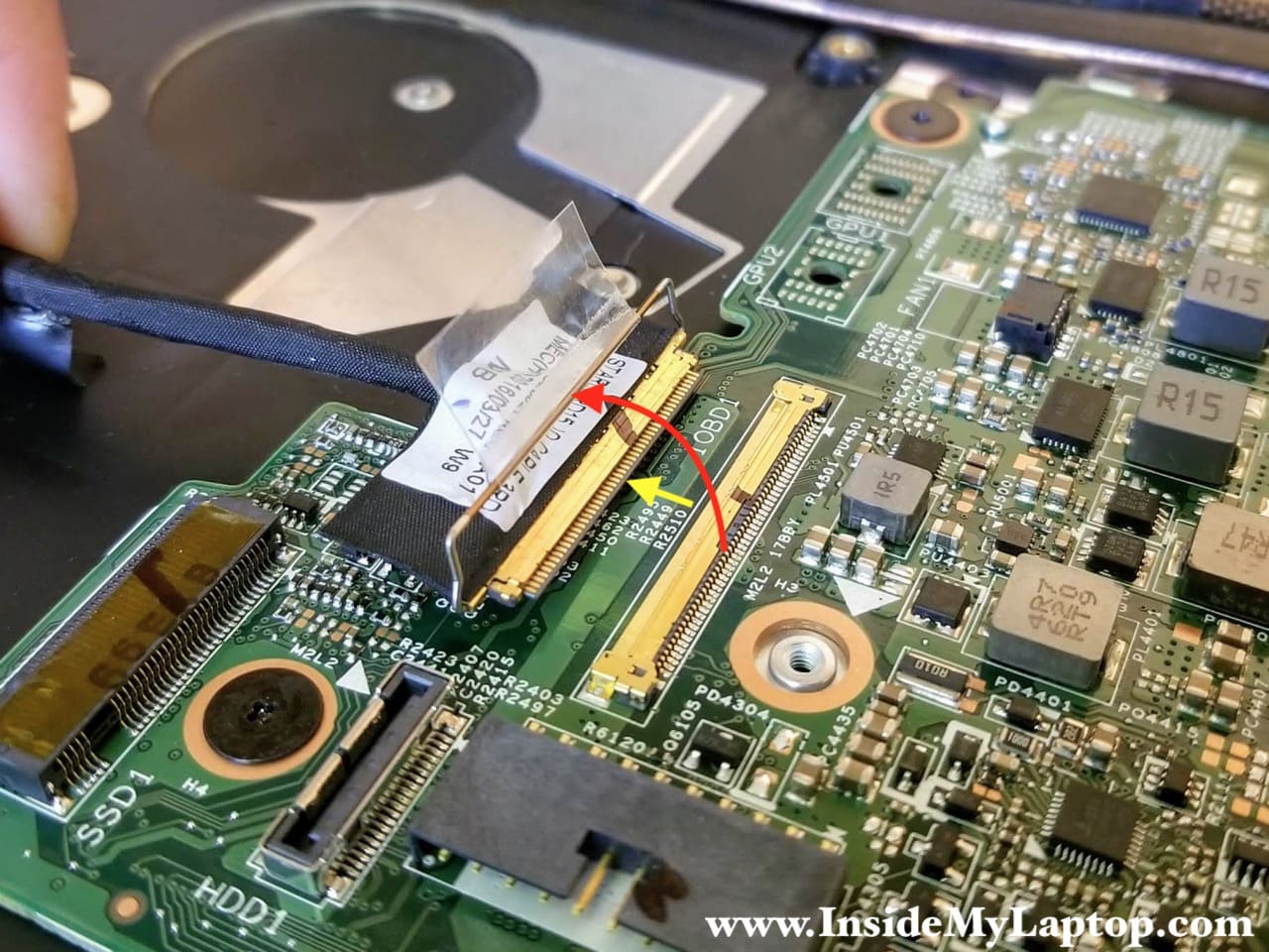
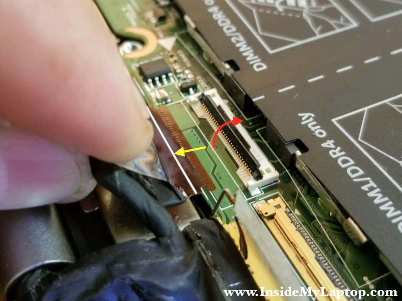
Here’s how to disconnect the I/O cable. Lift up the connector locking bracket first (red arrow) and after that pull the cable out (yellow arrow).
STEP 14.
Remove the USB/SD card reader board. The RTC battery is still attached to the board.
Motherboard removal
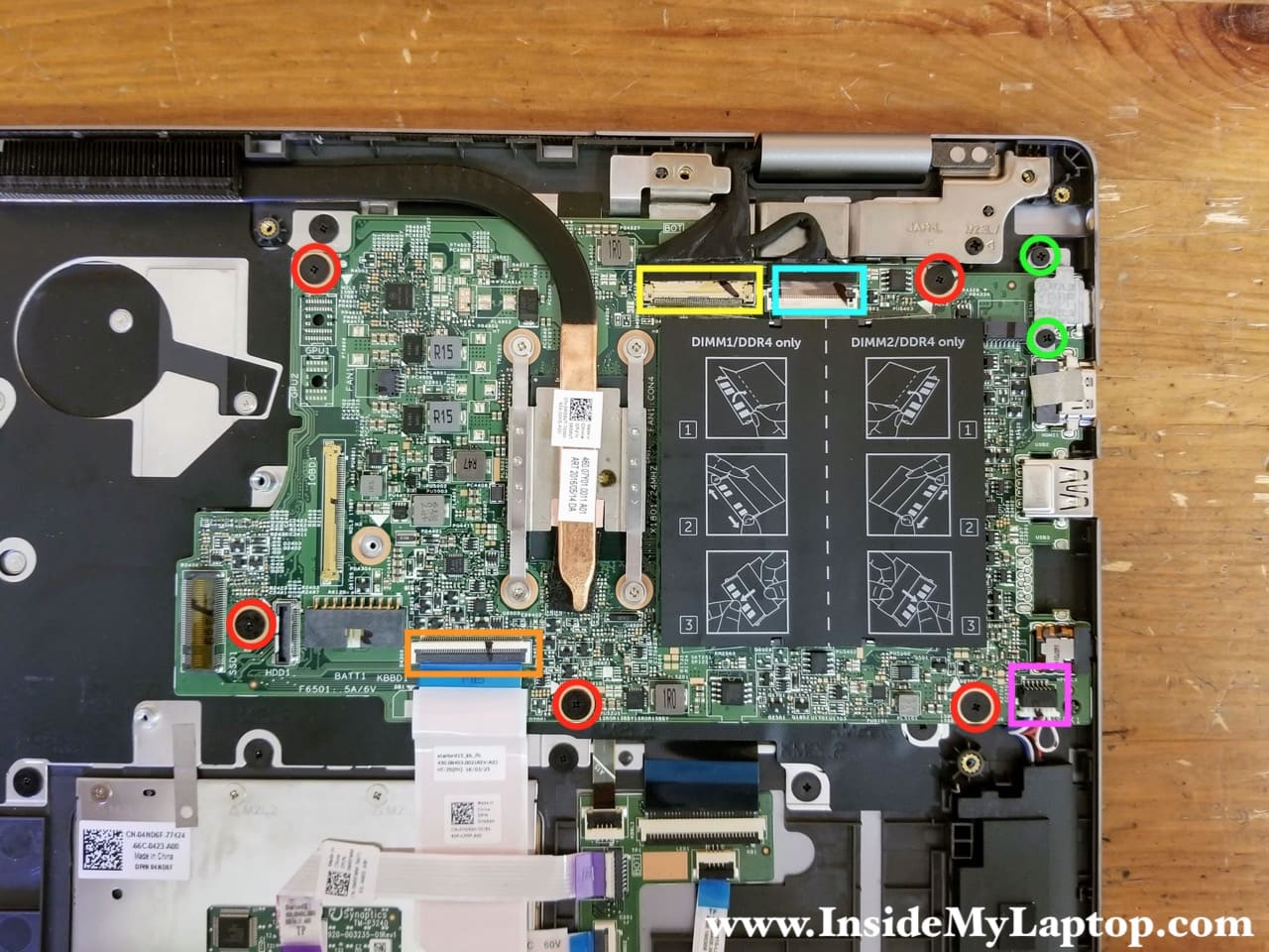
STEP 15.
Remove five screws securing the motherboard (red) and two screws from the USB-C port bracket (green).
Disconnect the keyboard/touchpad cable (orange), two display cables (yellow and blue) and one speaker cable (pink).
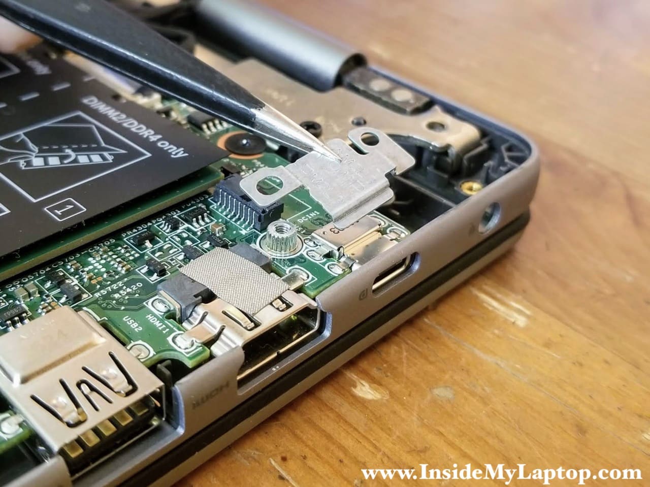
STEP 16.
Remove the USB-C port bracket.
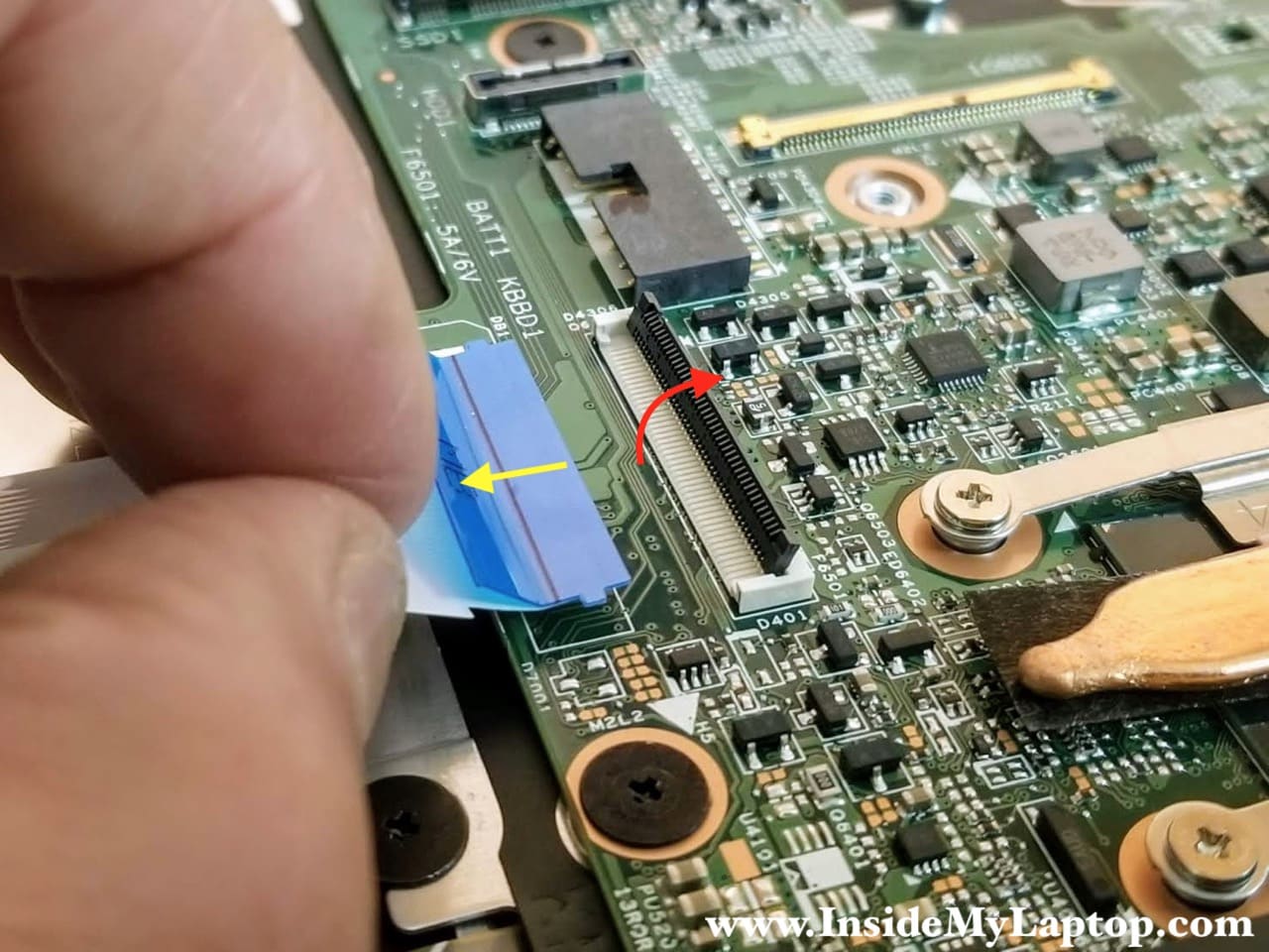
Here’s how to release the keyboard/touchpad cable. Lift up the locking tab (red arrow) to unlock the connector and pull the cable out.
Unlock the display cable connector and pull the cable out.
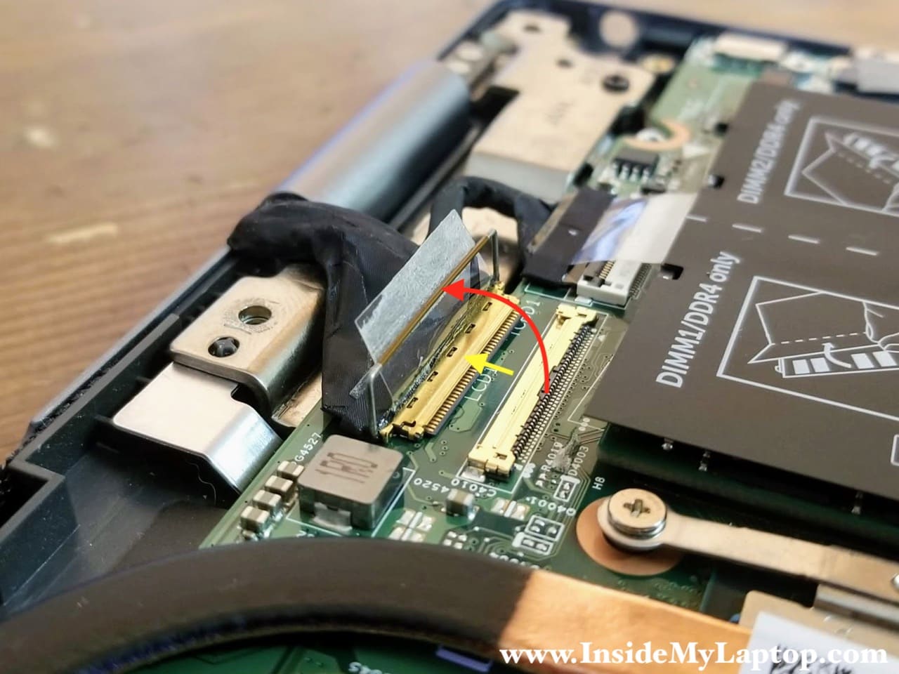
Disconnect the second display cable.
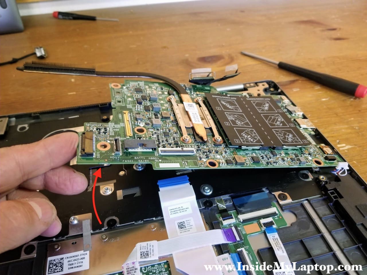
STEP 16.
Separate the motherboard from the top case assembly and remove it.
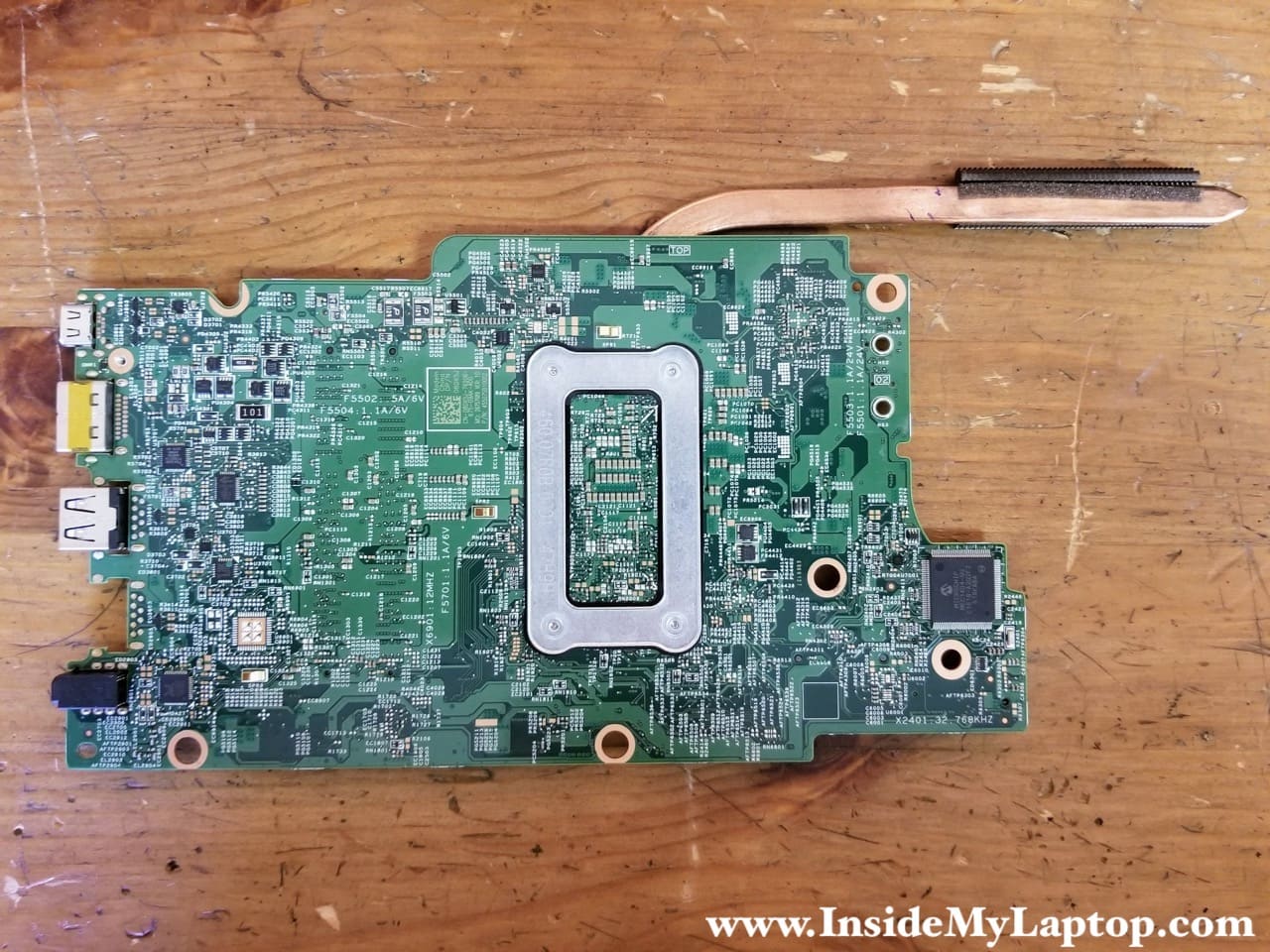
Here’s the other side of the motherboard.
Display panel removal
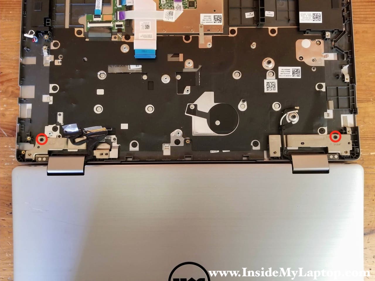
STEP 17.
Open the display panel 180 degrees. Remove two screws securing the left and right display hinges.
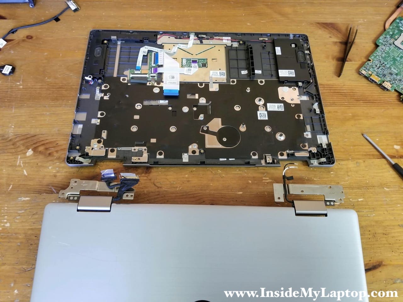
STEP 18.
Lift up and remove the display panel.
If your screen failed or you accidentally cracked the glass, check out my next guide about replacing the touchscreen on Dell Inspiron 5568 5578 5579 7569 7579 laptops.
As I mentioned earlier, the Dell Inspiron 15 7569 7579 keyboard can be removed. In order to remove the keyboard it’s necessary to remove the keyboard bracket first (secured by 16 screws) and after removing the bracket you can access and remove the keyboard (11 more screws).