
In this guide I show how to disassemble a Dell Inspiron 13 7386 (model P91G) 2-in-1 laptop.
During the disassembly process I found the following design features worth mentioning:
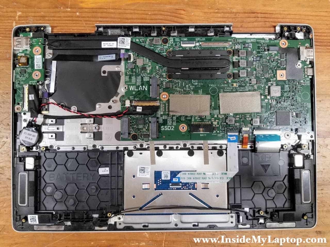
– There are two PCIe M.2 SSD slots on the motherboard.
– All memory soldered to the motherboard and there are no RAM expansion slots.
– The cooling fan can be easily removed and replaced.
– The DC power jack is not soldered to the motherboard.
– The keyboard is removable.
For this disassembly you will need just a few basic repair tools: Phillips #0 screwdriver, plastic spudger (optional) and tweezers.
Base cover and battery removal
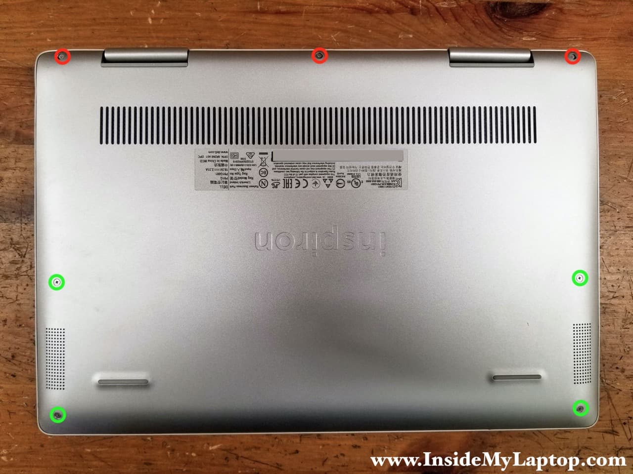
STEP 1.
Loosen three captive screws (red) and remove four screws (green) securing the base cover.
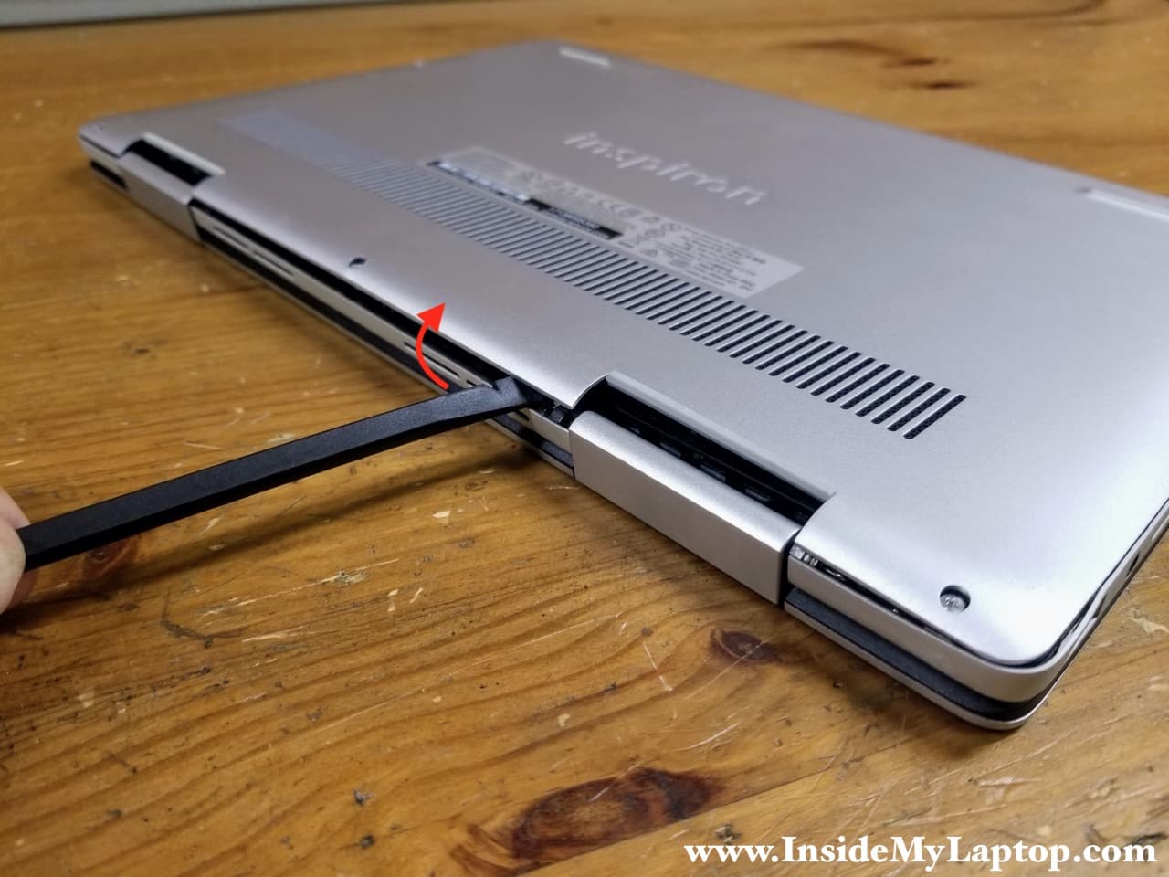
STEP 2.
Start separating the base cover from the top case somewhere around the display hinge area. Pry up the base cover.
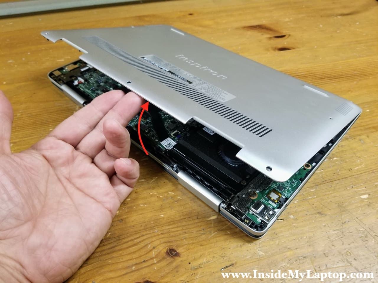
STEP 3.
Continue separating the base cover with your hands and remove it completely.
STEP 4.
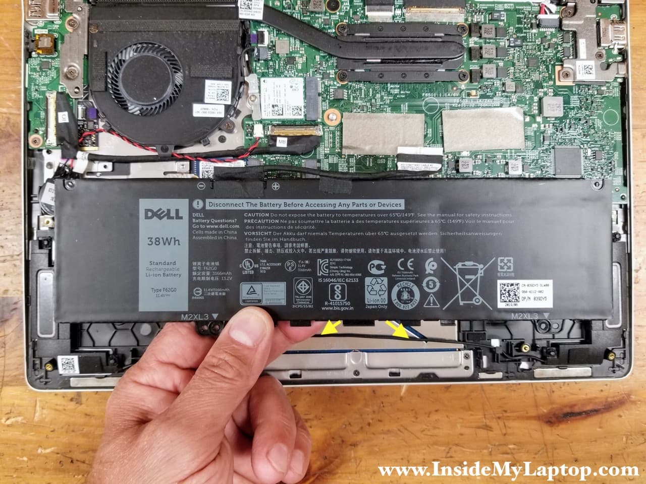
Remove four screws securing the battery and disconnect the battery cable from the motherboard.
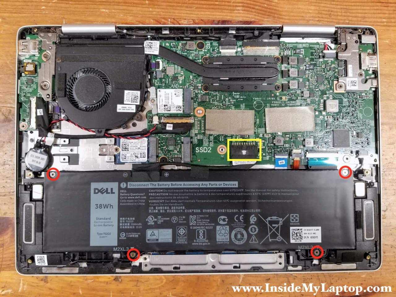
STEP 5.
Lift up the battery and remove the speaker cable from the guided path on the side of the battery.
Remove the battery.
Dell Inspiron 13 7386 (model P91G) battery type: F62G0. Dell part number: 039DY5.
SSD removal
STEP 6.
Remove one screw securing the PCIe M.2 NVMe SSD (type 2230). You can install more common type 2280 SSD in the slot SSD1, just move the screw mount closer to the coin-cell battery. Procedure to move the screw mount explained in the service manual on the page 26 (download link at the end of this guide).
As you see, the motherboard has another M.2 slot available on the right side. You can mount only type 2230 SSD in the slot SSD2. There is not enough space for a longer 2280 drive there.

STEP 7.
Pull the SSD out of the slot and remove it.

Cooling fan removal
STEP 8.
Remove two screws securing the cooling fan and disconnect the fan cable from the motherboard.

STEP 9.
Lift up and remove the fan.
Dell Inspiron 13 7386 (model P91G) fan part number: 0G0Y8C.

Wireless card removal
STEP 10.
Remove one screws securing the wireless card antenna cover. Remove the cover.

STEP 11.
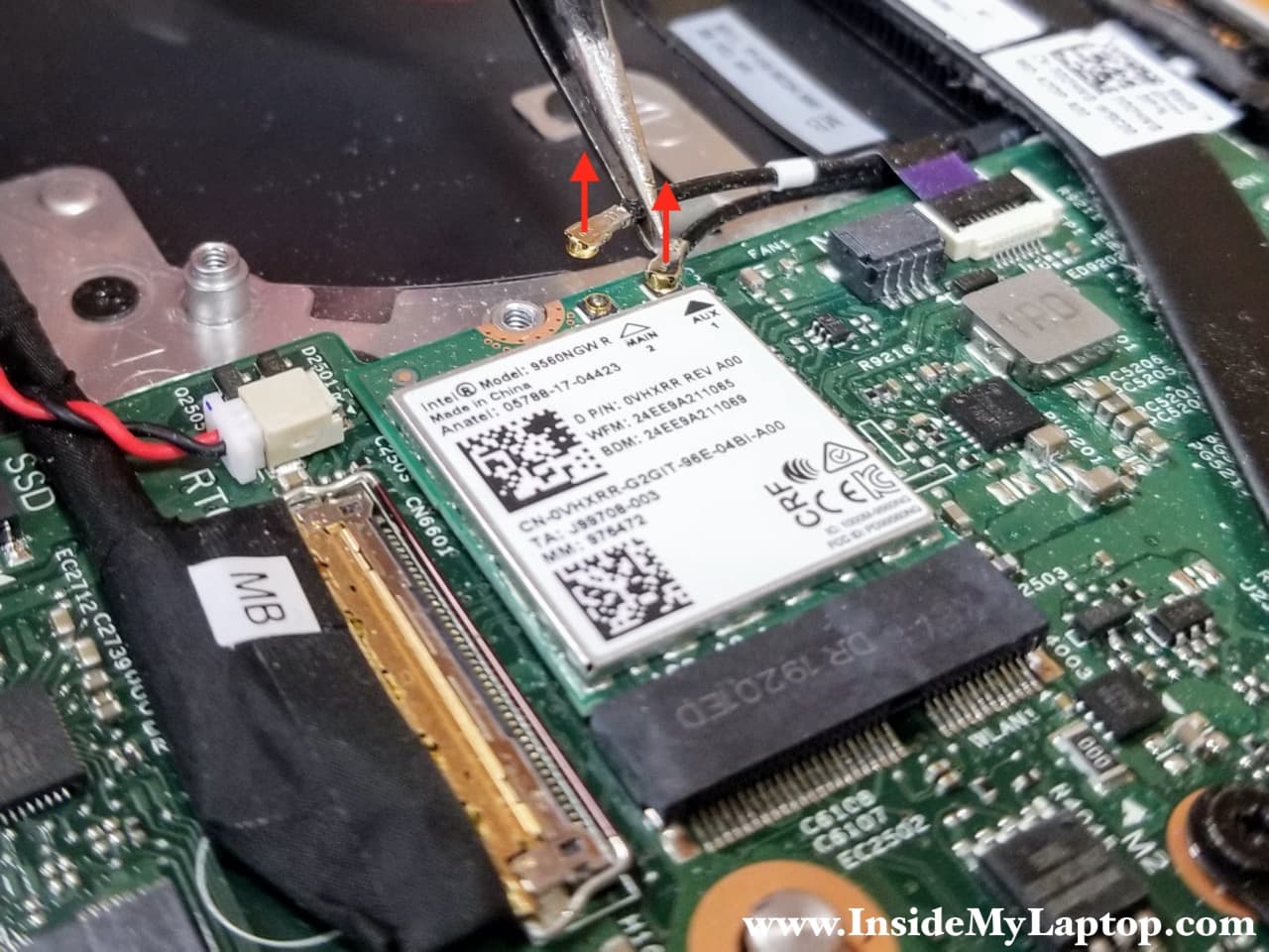
Disconnect both antenna cables from the wireless card.
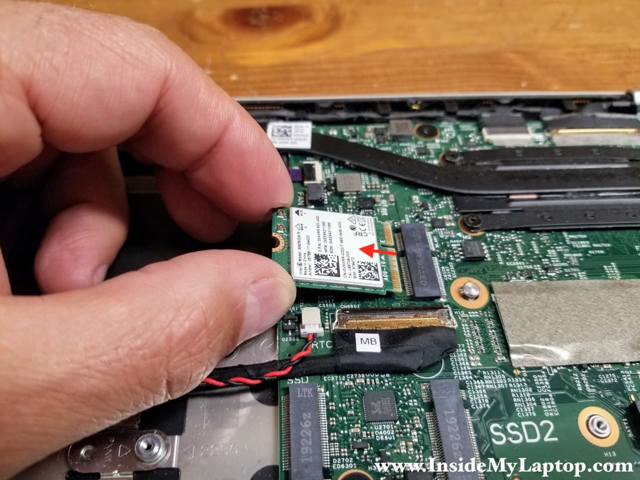
STEP 12.
Pull the wireless card out of the slot.
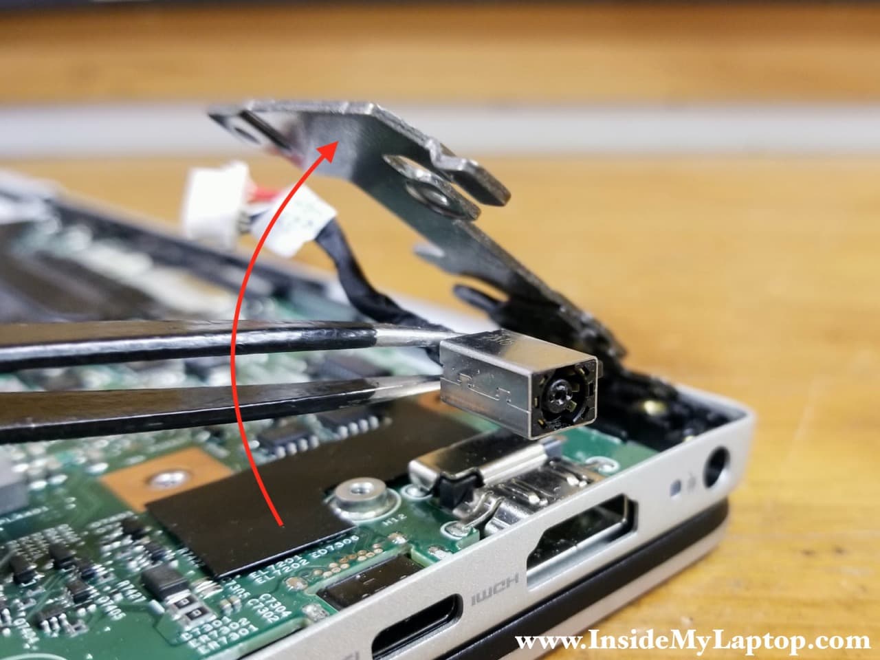
DC power jack removal
The DC power jack is mounted under the left display hinge. Let’s remove it next.
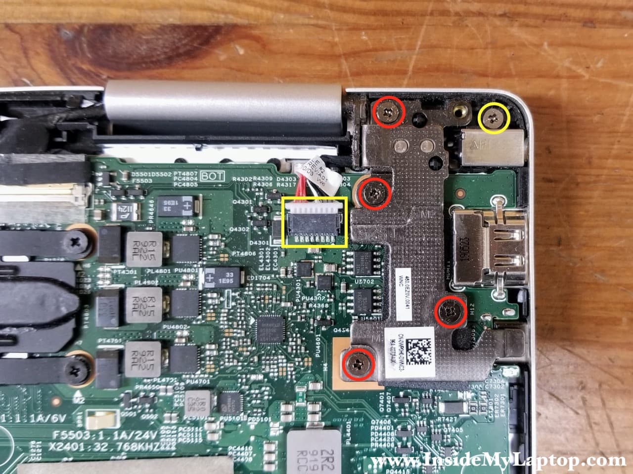
STEP 13.
Remove four screws securing the display hinges. Remove one screw from the DC power jack and disconnect the DC jack cable from the motherboard.
STEP 14.
Carefully lift up the hinge just enough to remove the DC jack. Lift up and remove the DC jack.
Display removal
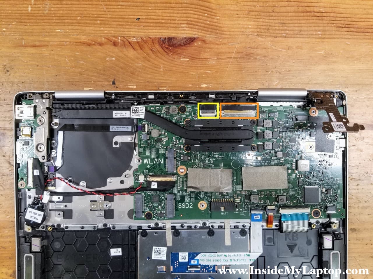
STEP 15.
Disconnect the touchscreen board cable (yellow) and the display cable (orange) from the motherboard.
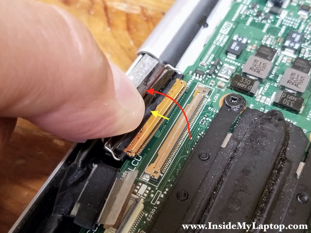
Here’s how to disconnect the touchscreen board cable.
Lift up the locking tab to unlock the connector (red arrow). Lift up and pull the cable out (yellow arrow).

The display cable also has to be unlocked first. You’ll have to lift up the metal bracket securing the connection.
STEP 16.
Remove the display cable from the guided path.
Disconnect the fingerprint reader cable (red box).

STEP 17.
Carefully pull both Wi-Fi antenna cable through the opening under the heatsink.

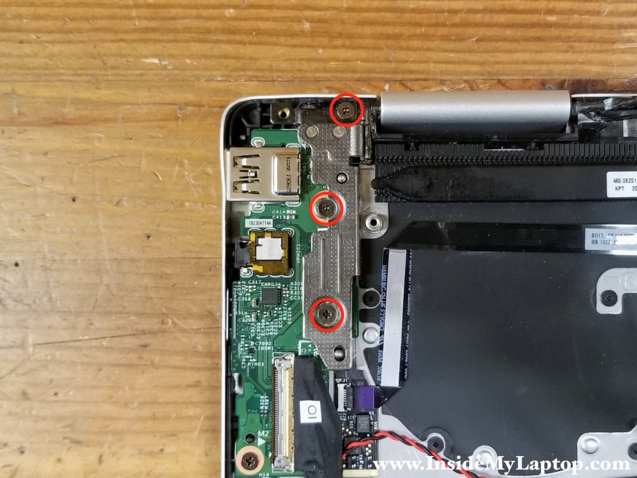
STEP 18.
Remove three screws securing the right display hinge.
As you remember, we removed screws from the left hinge in the step 13.
STEP 19.
Carefully open the display panel as it shown on the following picture. Secure both hinges with your hands while opening up the display.

STEP 20.
Separate the top case assembly from the display panel.

Dell Inspiron 13 7386 (model P91G) has a sealed display which cannot be easily disassembled.

Motherboard and I/O board removal
When the display panel is removed you can access and remove the motherboard with the I/O board.
In order to remove the motherboard it’s necessary to remove three screws and disconnect the following color-coded cables:
– Coin-cell battery cable (pink).
– I/O board cable (orange).
– Touchpad cable (yellow).
– Keyboard backlight and keyboard cable (green).
– Speaker cable (blue).
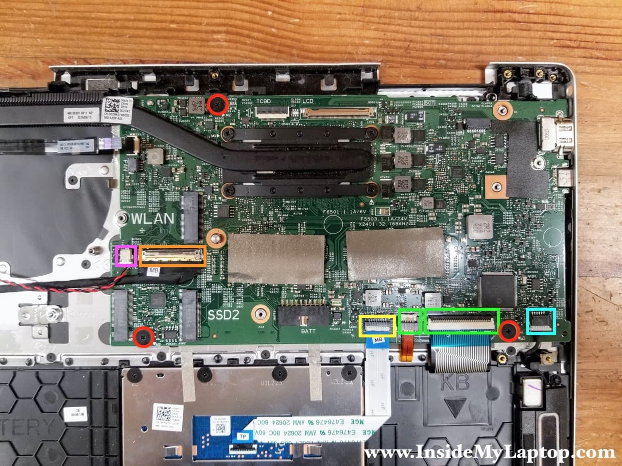
The I/O board (USB, audio jack, card reader board) can be easily removed too. Simply remove one screw and disconnect the I/O cable (yellow) and fingerprint scanner cable (orange).
