In this post I present you a teardown of Dell Inspiron 13 7000 series laptop (regulatory model P57G). You can use this disassembly guide for Dell Inspiron 13-7353, Inspiron 13-7359 and probably some other models too.
In this guide I’m taking apart only the laptop base. For the display disassembly and screen replacement check out my next post: Replacing touchscreen on Dell Inspiron 7347 7348 7352 7353 7359.
STEP 1.
Remove ten screws securing the bottom cover.

STEP 2.
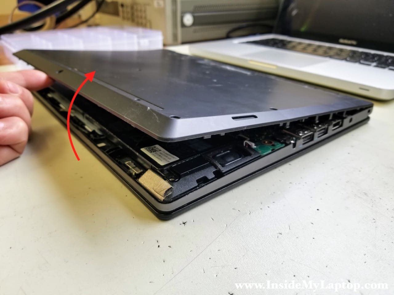
Using a thin case opening tool separate the bottom cover from the top case.
Insert the case opener between two halves and move it along the edge to unfasten hidden latches.

STEP 3.
You’ll have to apply some reasonable force in order to separate the bottom cover from the top case. Remove the cover.
STEP 4.
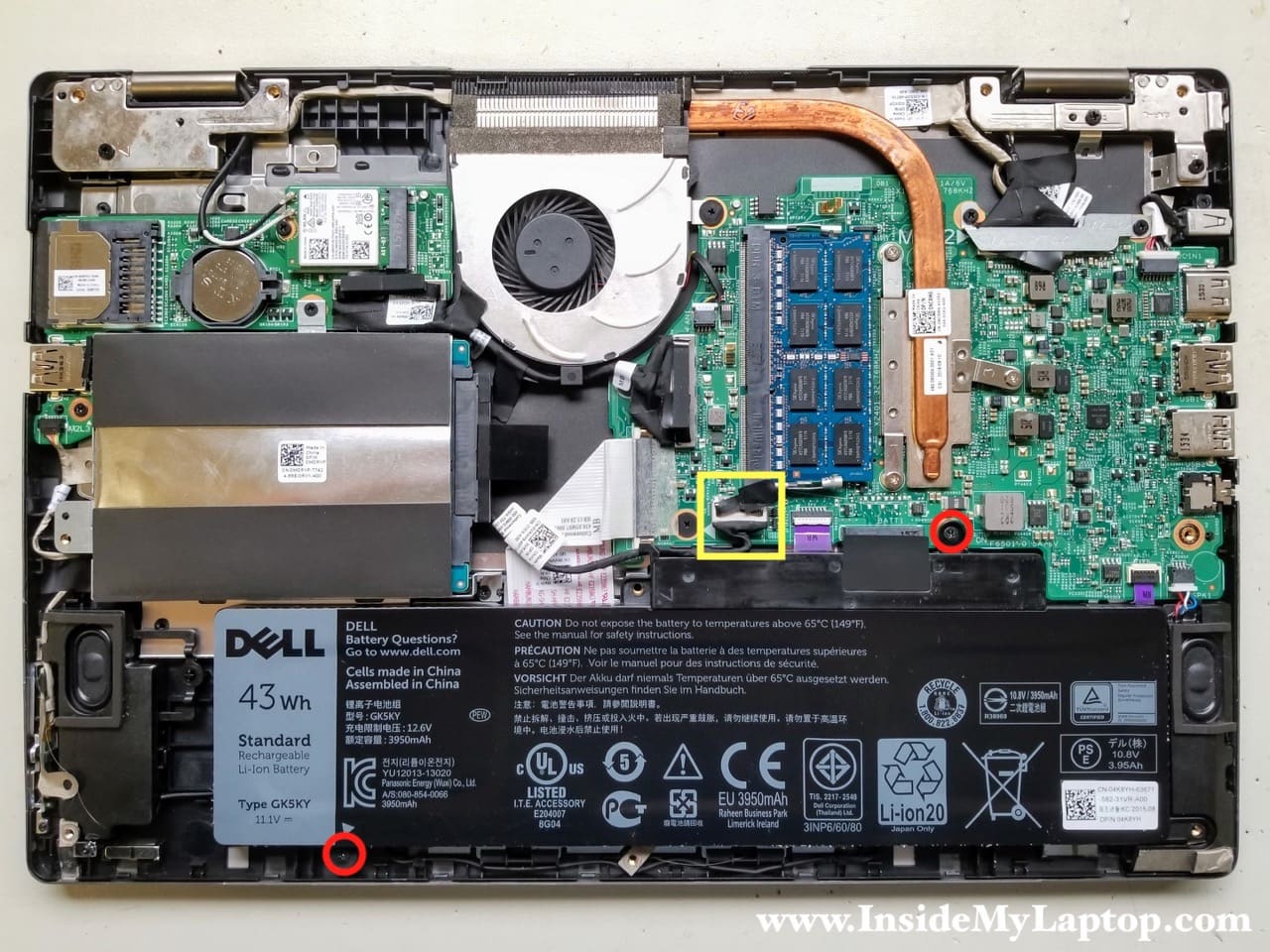
Remove two screws securing the battery and unplug the cable from the motherboard.
While removing the battery, it’s necessary to un-route the hard drive cable from the guided path on the side of the battery.
Replacement batteries type GK5KY.
STEP 5.
Remove two screws from the hard drive caddy.
Disconnect the hard drive SATA cable from the motherboard.
Remove the hard drive assembly.

If you are upgrading or replacing the hard drive, you will have to transfer the caddy and SATA cable to the new one.
I recommend upgrading this regular hard drive to a 2.5″ SATA solid state drive to improve laptop performance.

STEP 6.
Dell Inspiron 7353/7359 laptop has only one removable RAM module.
Remove the memory module if necessary. You can leave it connected to the motherboard.
You can install up to 8GB DDR3-12800 SODIMM module into this slot.

STEP 7.
Disconnect the I/O cable on both ends.
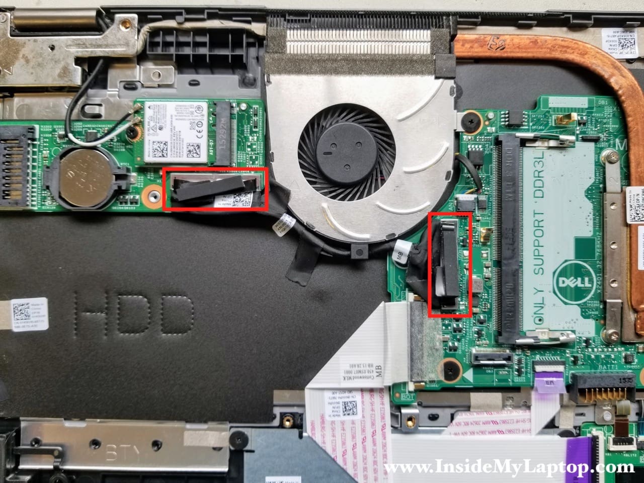
In order to unplug the cable connector from the motherboard simply lift it up using the pull tab on the top. Remove the cable.

STEP 8.
Disconnect both wireless antenna cables from the WLAN card.
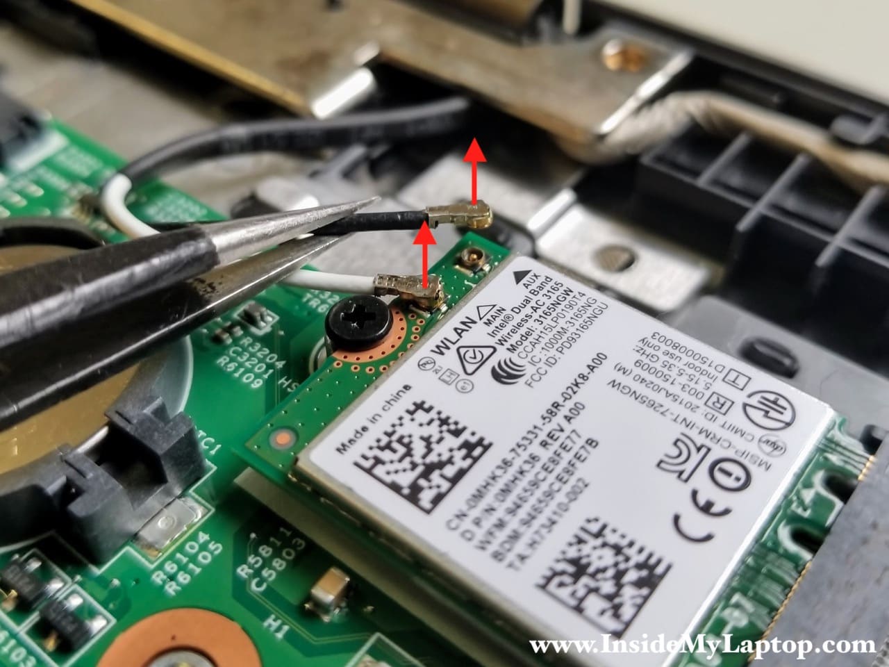
STEP 9.
Remove one screw securing the WLAN card and pull it out of the slot.

STEP 10.
Disconnect the power button board cable from the I/O board (USB SD card reader board).
Remove one screw fastening the board to the top case.

STEP 11.
Remove the I/O board.
As you noticed, the CMOS battery also located on the I/O board.

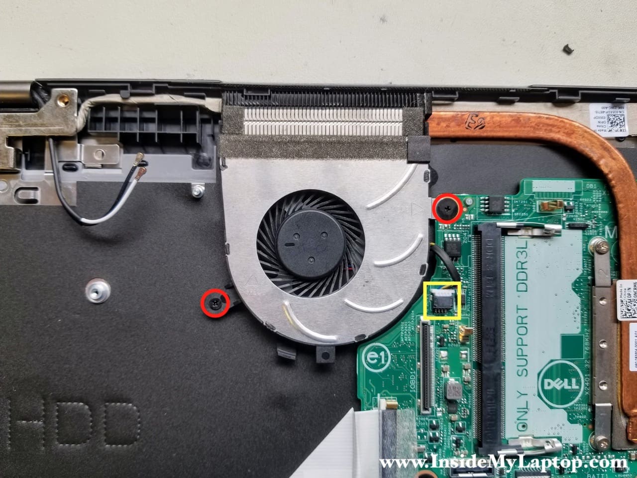
STEP 12.
Remove two screws from the cooling fan.
Disconnect the fan cable.
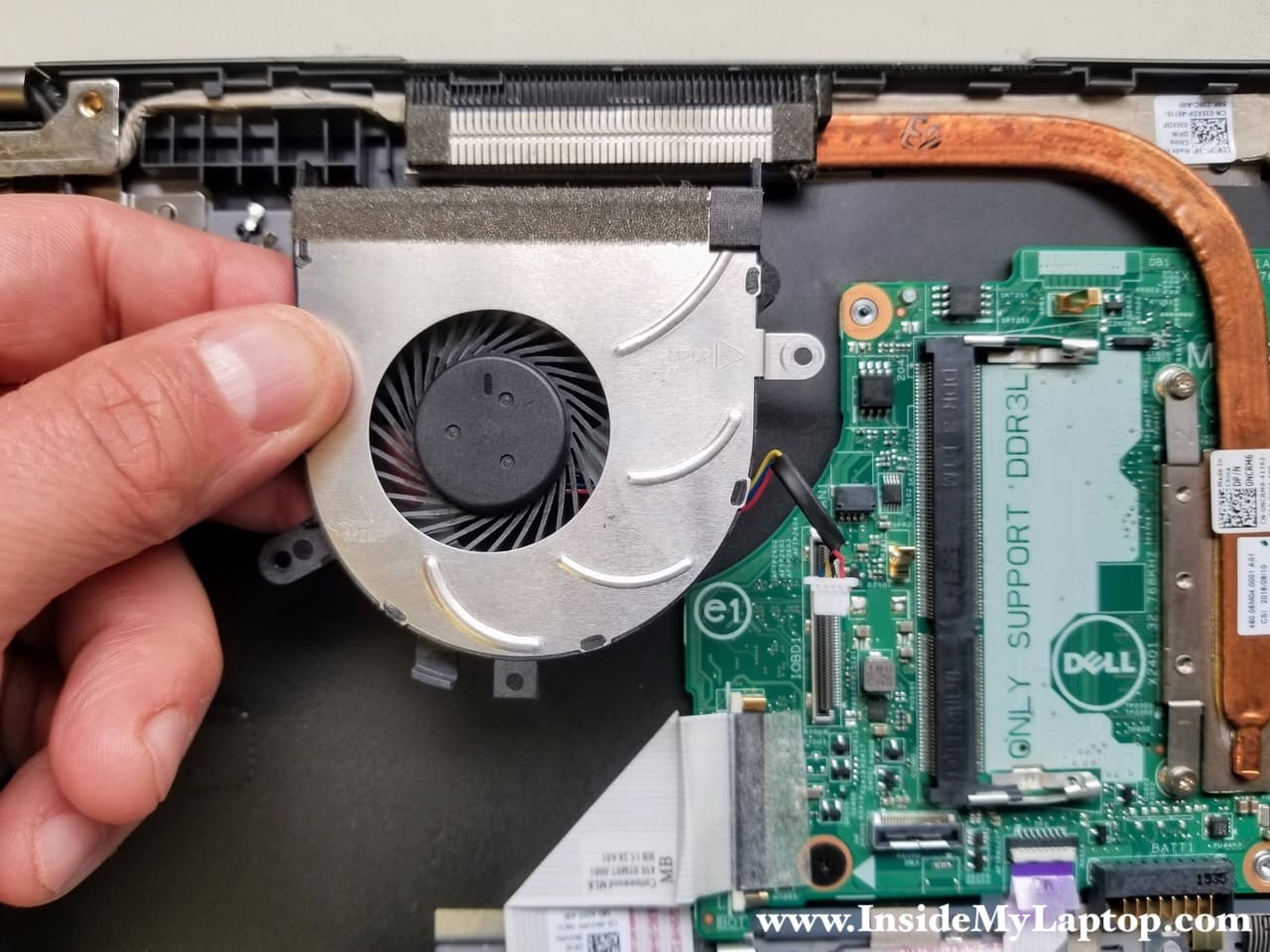
STEP 13.
Remove the cooling fan.
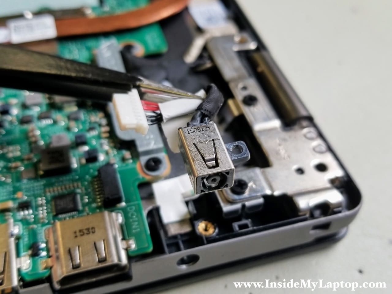
STEP 14.
Remove one screw securing the DC-IN power jack and disconnect the cable.

STEP 15.
Remove the DC-IN power jack.
STEP 16.|
Disconnect the following cables:
- Keyboard cable (red rectangular)
- Touchpad cable (orange square)
- Keyboard backlight cable (yellow square)
- Speaker cable (green square)
Remove two screws securing the display cable bracket and remove it.
Under the bracket you will find two cables:
- Display video cable
- Windows button board cable

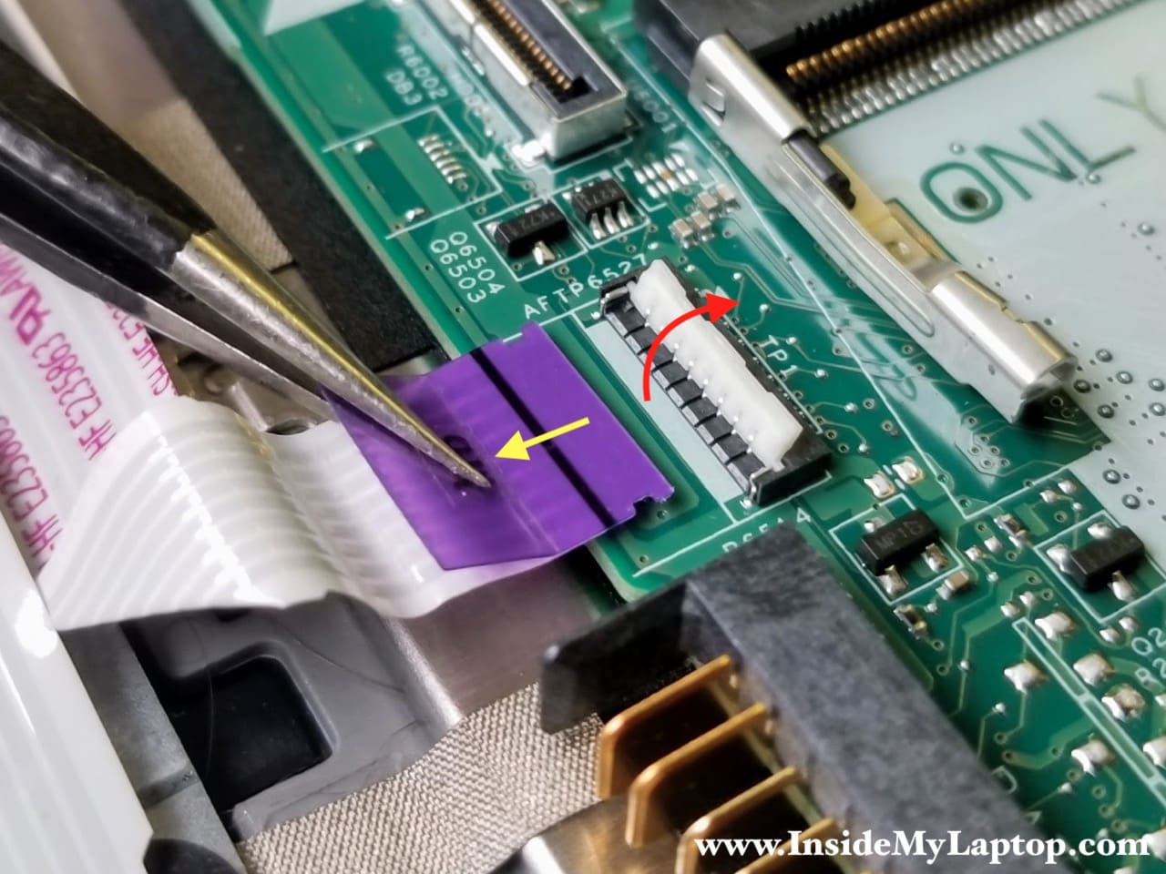
Here’s how to release the keyboard cable.
- Slide the connector locking tab about 2 millimeters to the shown direction (two red arrows)
- Pull the keyboard cable out of the connector.

Here’s how to disconnect the touchpad and keyboard backlight cables:
- Lift up the locking tab (red arrow)
- Pull the cable out
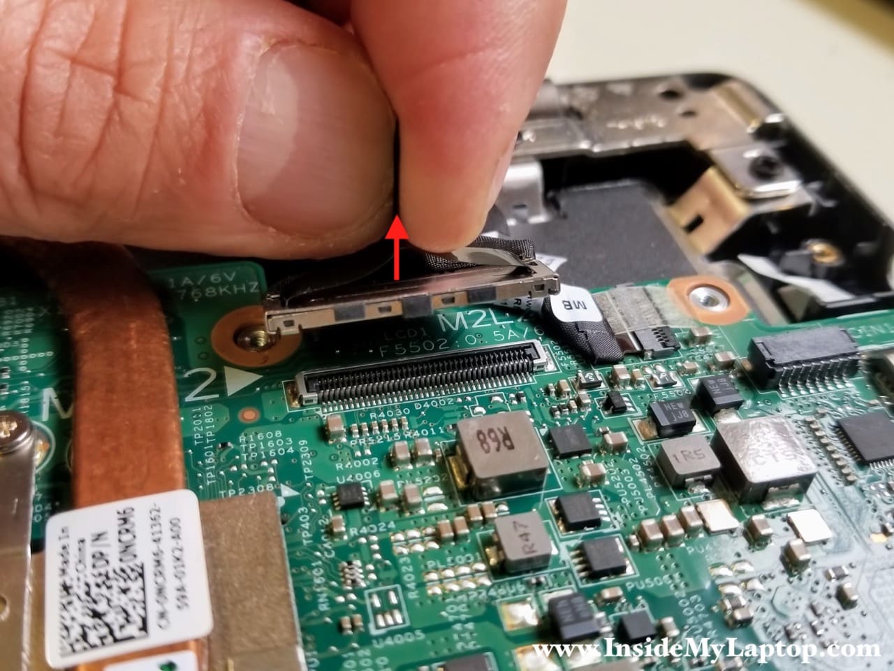
Disconnect the display video cable (located under the metal bracket) using the pull tab on the top.
Here’s how to release the Windows button board cable:
- Unlock the connector
- Pull the cable out

STEP 17.
Remove one screw securing the motherboard.

STEP 18.
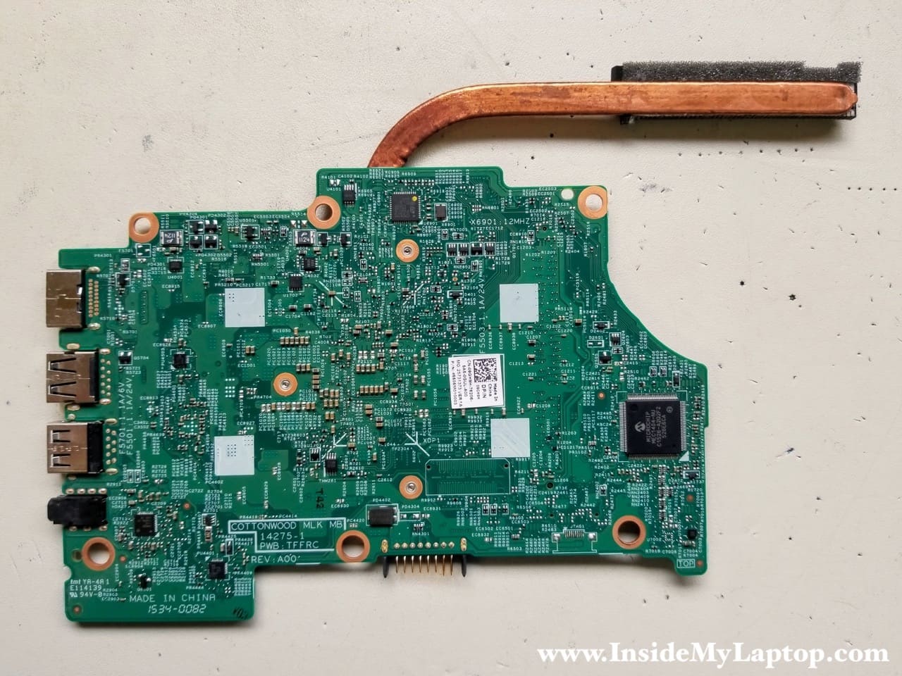
Separate the motherboard from the top case and remove it.

Here’s a picture of the other side of the motherboard in case you need it.
Dell Inspiron 13 7000 series laptop has the keyboard permanently attached to the top case.
The metal plate that covers the keyboard is riveted to the top case and cannot be easily removed.
If you have failed keyboard, you will have to replace the entire top case or try this trick.

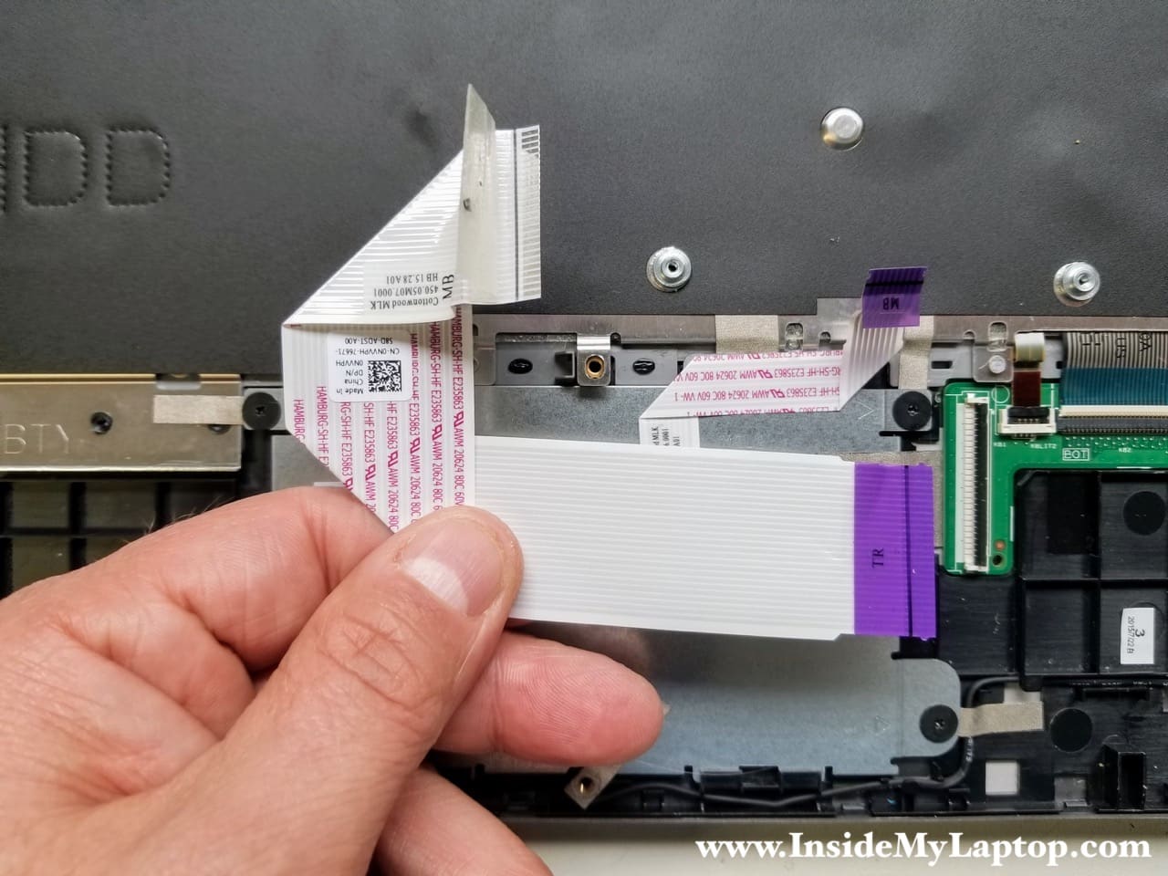
STEP 19.
Disconnect and remove the keyboard cable.
STEP 20.
Remove four screws from the touchpad mounting bracket.

STEP 21.
Remove the touchpad mounting bracket.
While removing it it will be necessary to peel off grounding tape.

STEP 22.
Remove the touchpad.

leonidas
I think that what you and yours do for us(people curious, or needing info)is . amazing. simply put I appreciate it. I know all the time involved and effort, monotonous and time consuming, many don’t see or care…most. I give my support, I think its solid and like the research and please continue to help people diy
brian
great review, but how do I get into the keyboard to clean it?
IML Tech
Brian, you cannot remove the keyboard. It’s permanently attached to the palmrest assembly.