In this guide I will walk you through the process of complete disassembly of Lenovo Y50-70 (model 20378) laptop.There will be two parts in this disassembly guide.
- Taking apart the laptop case. I will show how to access and remove all internal components.
- Taking apart the display panel. I will show how to remove and replace the LCD screen.
These two parts are independent from each other and if all you need is to replace the screen, you can jump straight to the second part.
Part 1. Taking apart Lenovo Y50-70 laptop case.
STEP 1.
Remove all screws securing the bottom cover.

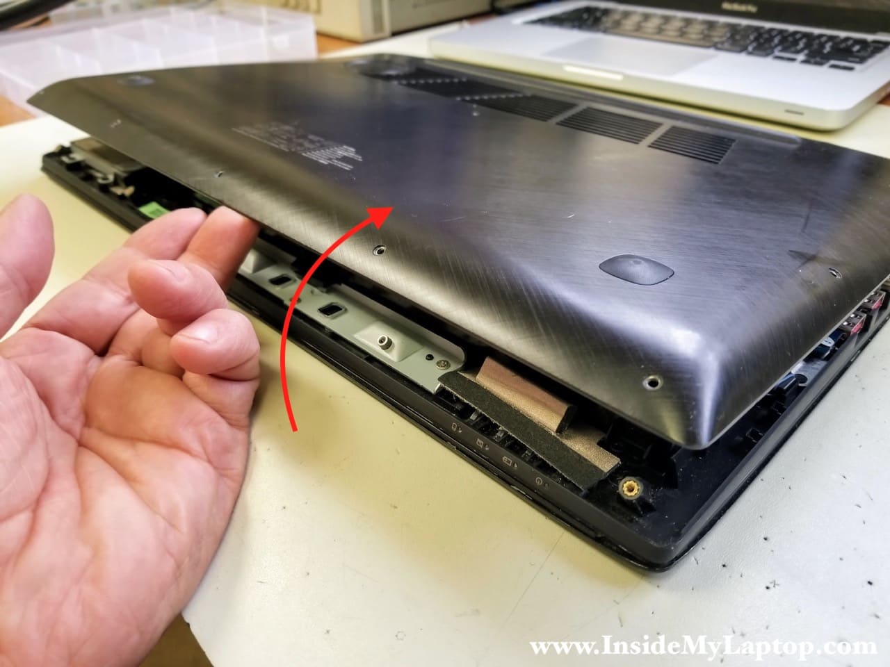
STEP 2.
Lift up the cover and remove it.
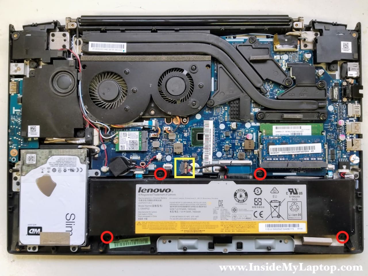
STEP 3.
Remove three screws securing the battery and disconnect the cable from the motherboard.
Remove the battery.
Replacement batteries model L13M4P02.
STEP 4.
Remove four screws from the hard drive caddy and disconnect the SATA cable from the motherboard.
Remove the hard drive assembly.
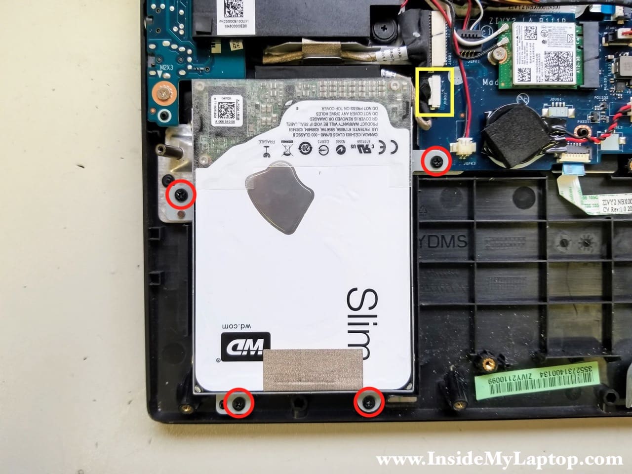
STEP 5.
If you are replacing the hard drive or upgrading it, you will have to transfer the caddy and the cable to the new one.
I recommend upgrading this regular hard drive to a 2.5″ SATA solid state drive to improve laptop performance.

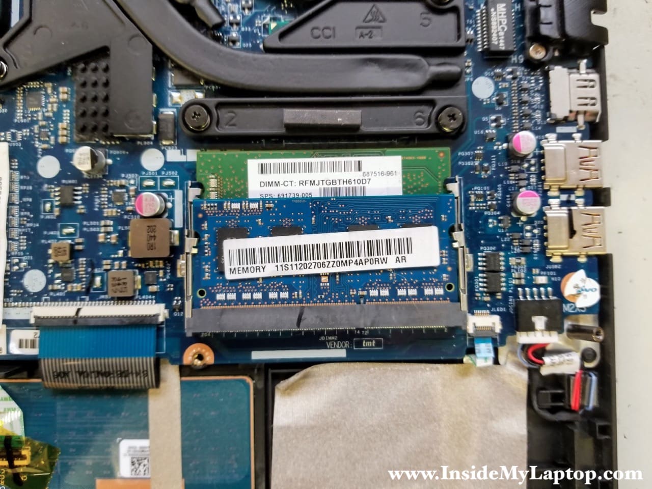
STEP 6.
Lenovo Y50-70 laptop has two removable memory modules. Remove both modules if necessary.
You can install up to 16GB (2x8GB) DDR3-12800 SODIMM RAM modules into these slots.
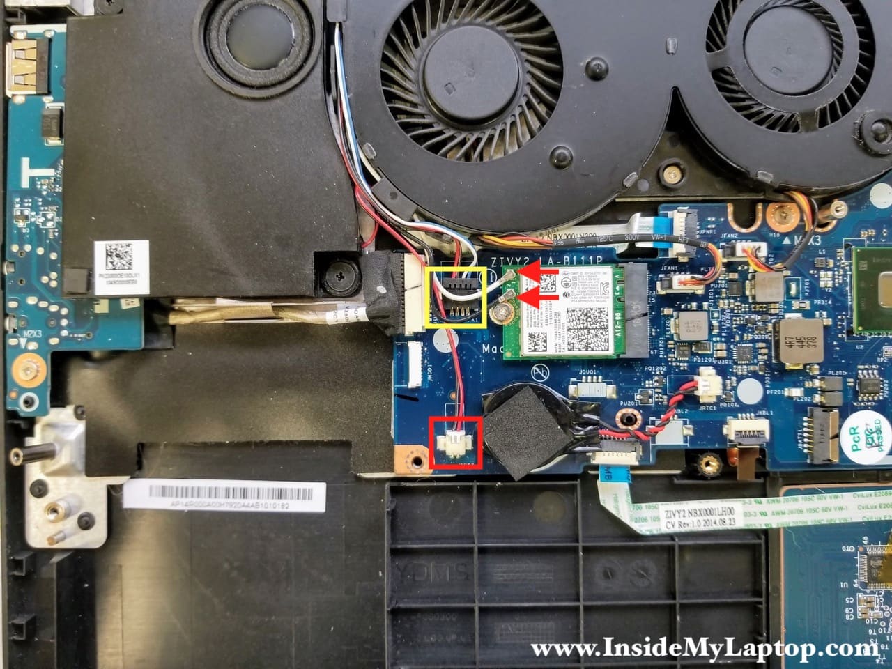
STEP 7.
Disconnect the subwoofer cable (red square).
Disconnect the speaker cable (yellow square).
Disconnect two antenna cables (red arrows) from the wireless card. You can leave the wireless card connected to the motherboard unless you have to replace it.
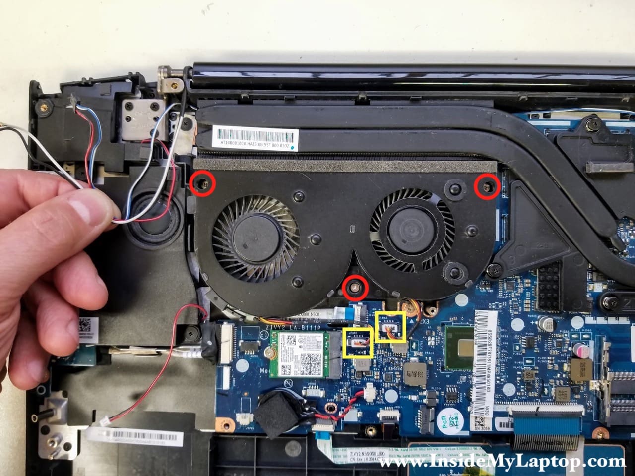
STEP 8.
Un-route cables from the left side of the cooling fans assembly.
Remove three screws securing the dual fan assembly.
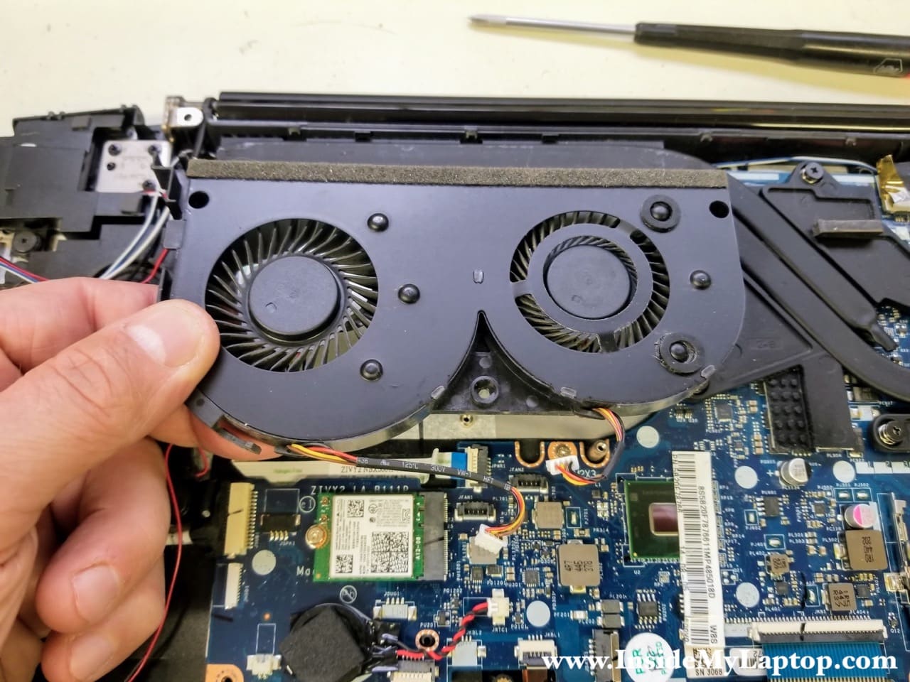
STEP 9.
Remove the cooling fan assembly.
STEP 10.
Remove two screw securing the subwoofer and remove it from the laptop.
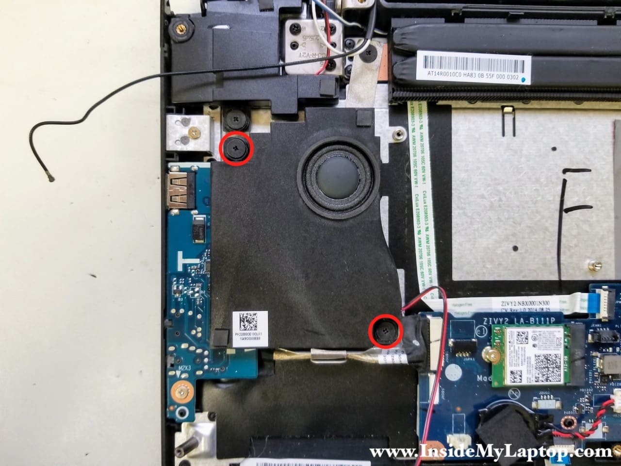
STEP 11.
Remove two screws from the USB Audio SD card reader board.
Disconnect the board cable from the motherboard.

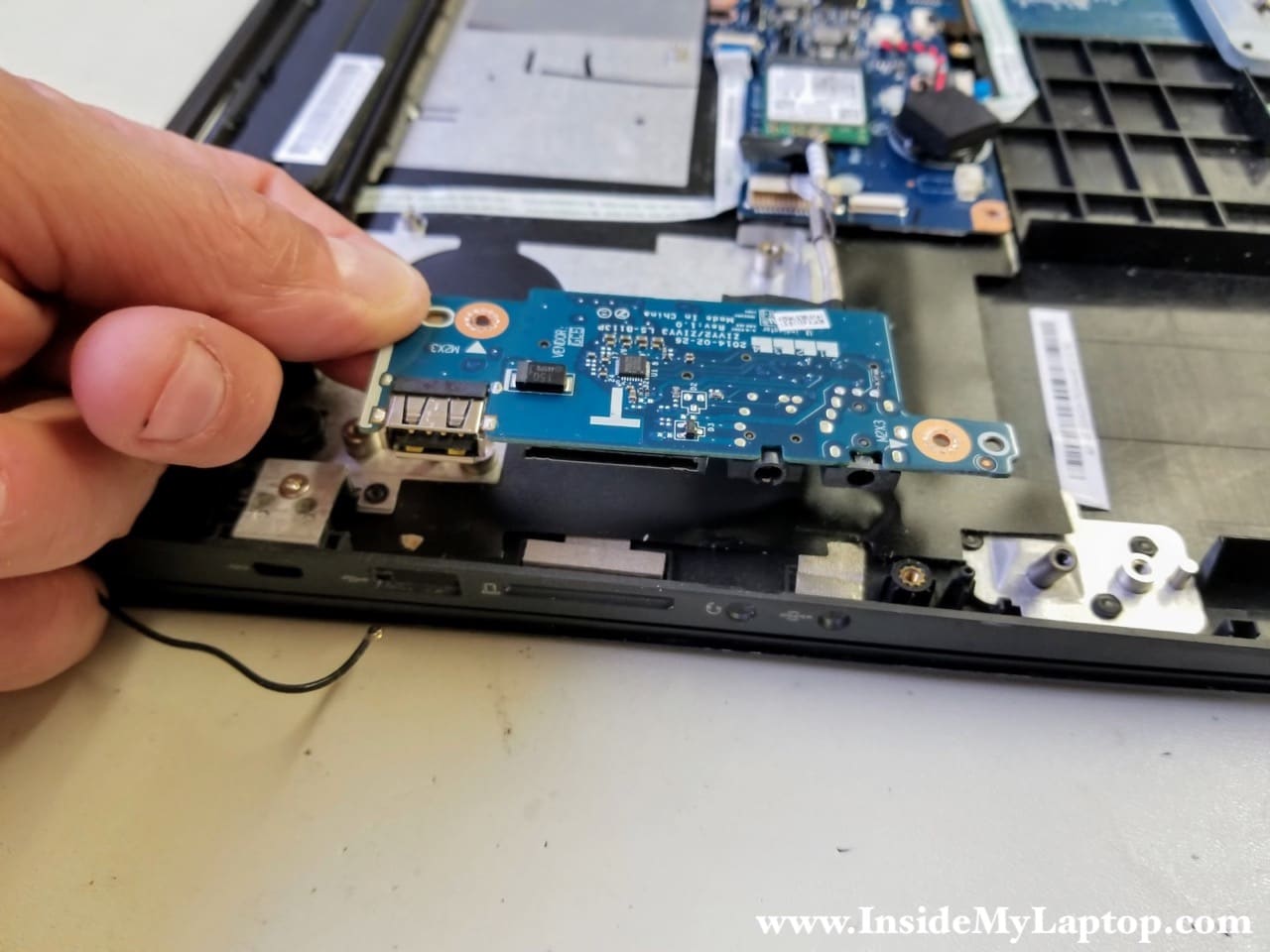
STEP 12.
Remove the USB Audio SD card reader board.
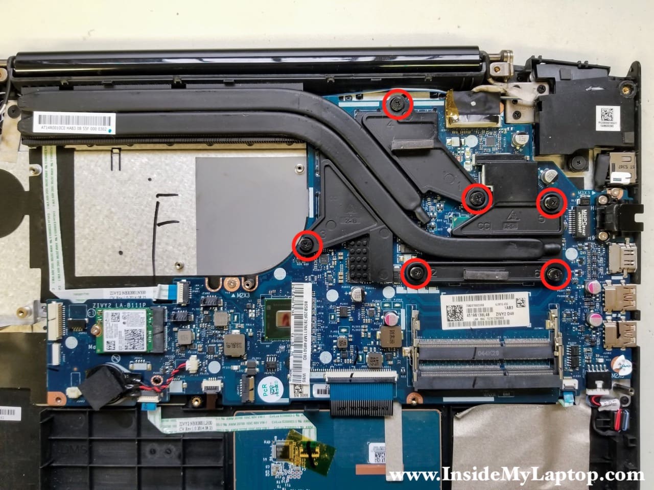
STEP 13.
Remove six spring loaded screws fastening the heatsink.
You cannot remove the motherboard without removing the heatsink first.
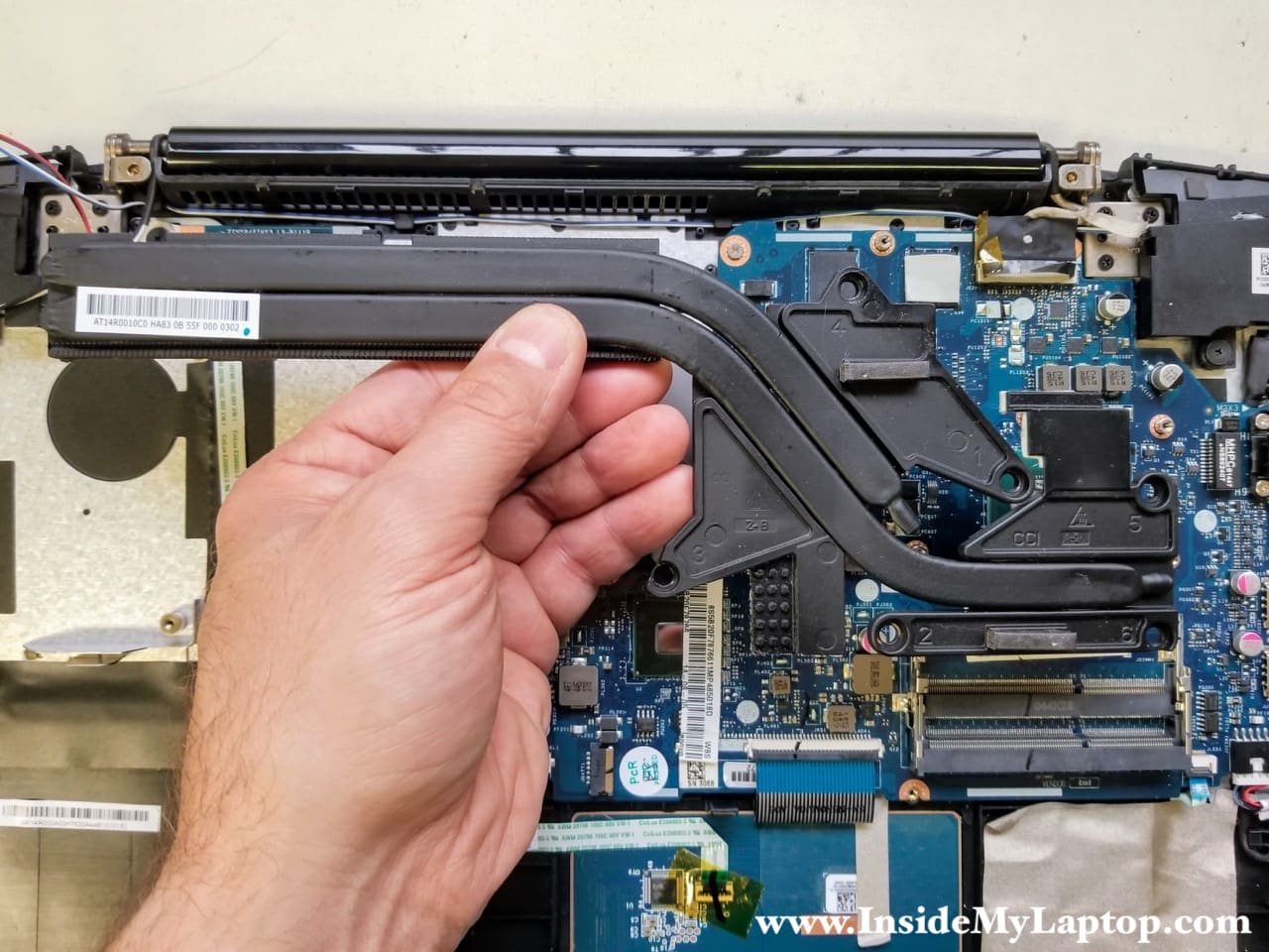
STEP 14.
Remove the heatsink.
STEP 15.
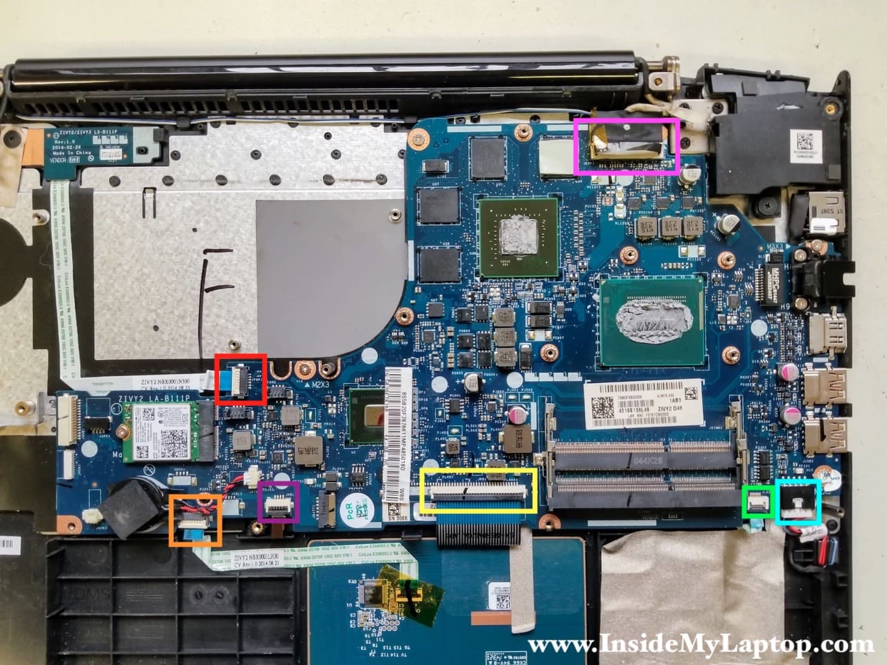
Disconnect the following cables from the motherboard:
- Power button board cable (red square)
- Touchpad cable (orange square)
- Keyboard backlight cable (purple square)
- Keyboard data cable (yellow rectangular)
- LED status board cable (green square)
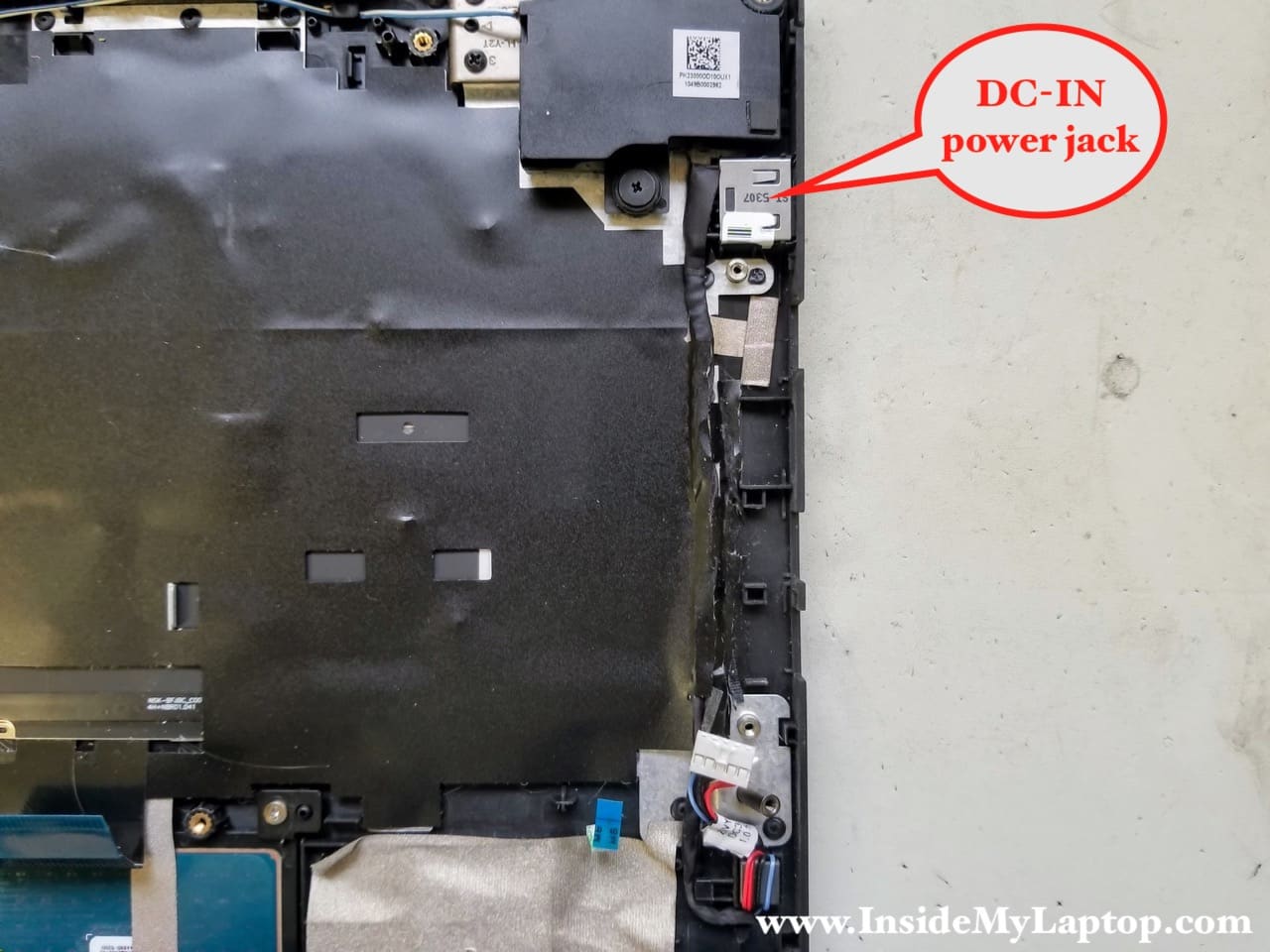
- DC-IN power jack cable (blue square)
- LCD screen video cable (violet square)
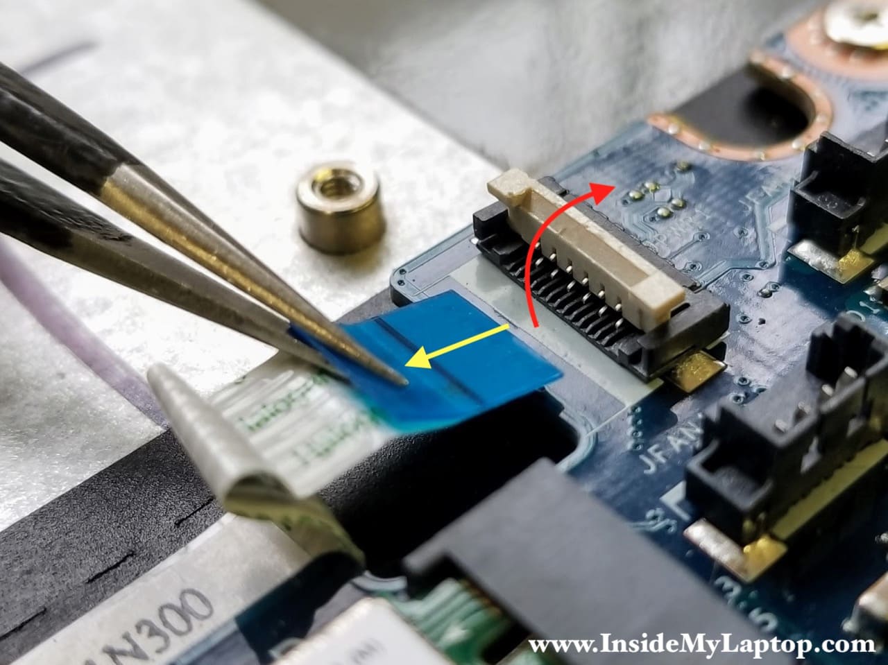
Here’s how to release flat cables:
- Unlock the connector by lifting up the locking tab.
- Pull the cable out of the connector.
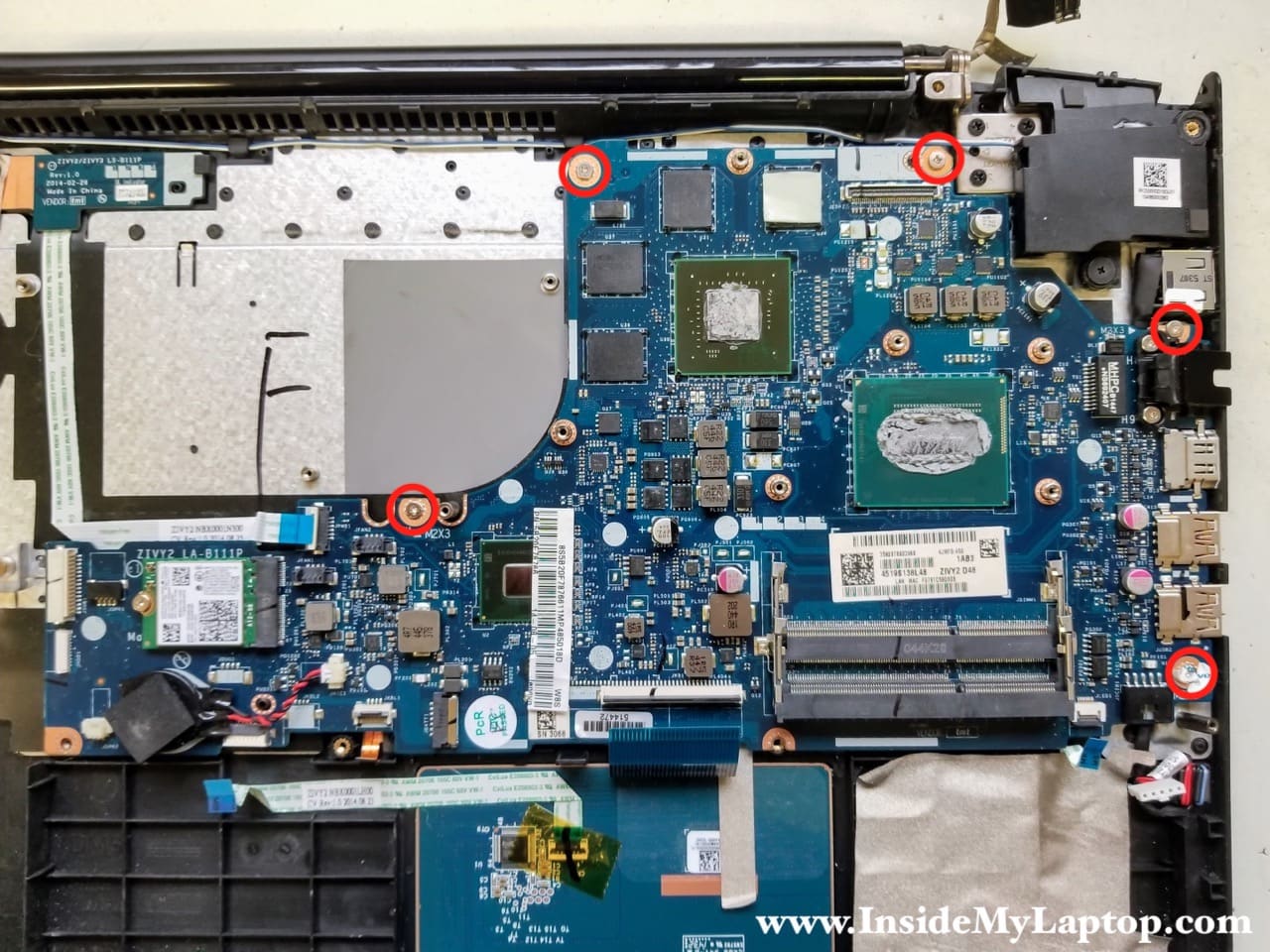
STEP 16.
Remove five screws attaching the motherboard to the top case.
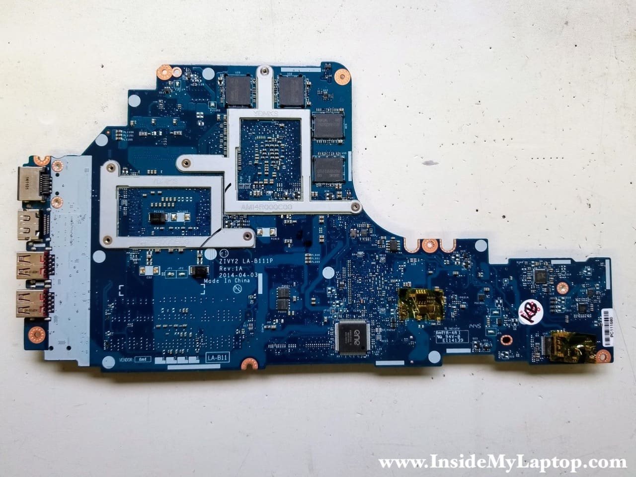
STEP 17.
Remove the motherboard from the case.
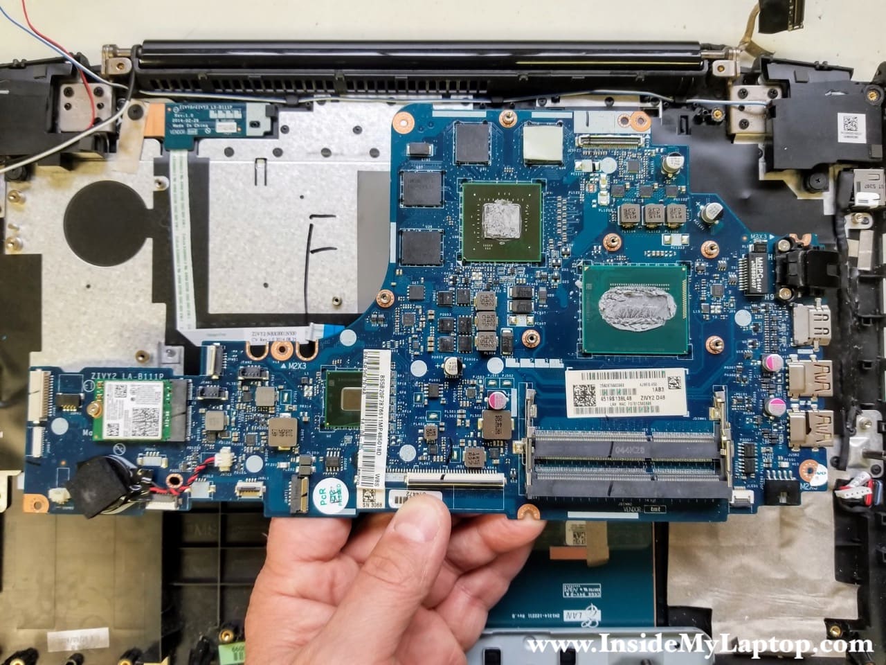
Here’s a picture of the other side just in case you need it.
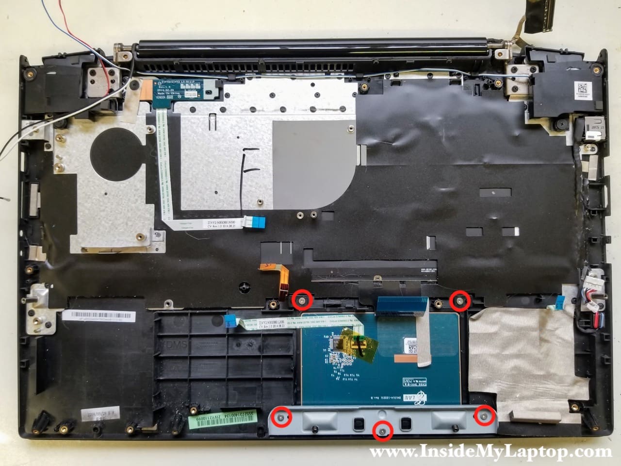
STEP 18.
The touchpad can be removed after you remove three screws from the metal bracket and two more from the touchpad itself.
The keyboard is permanently attached to the top case and cannot be easily removed. If the keyboard failed, you will have to replace the entire top case or try this repair.
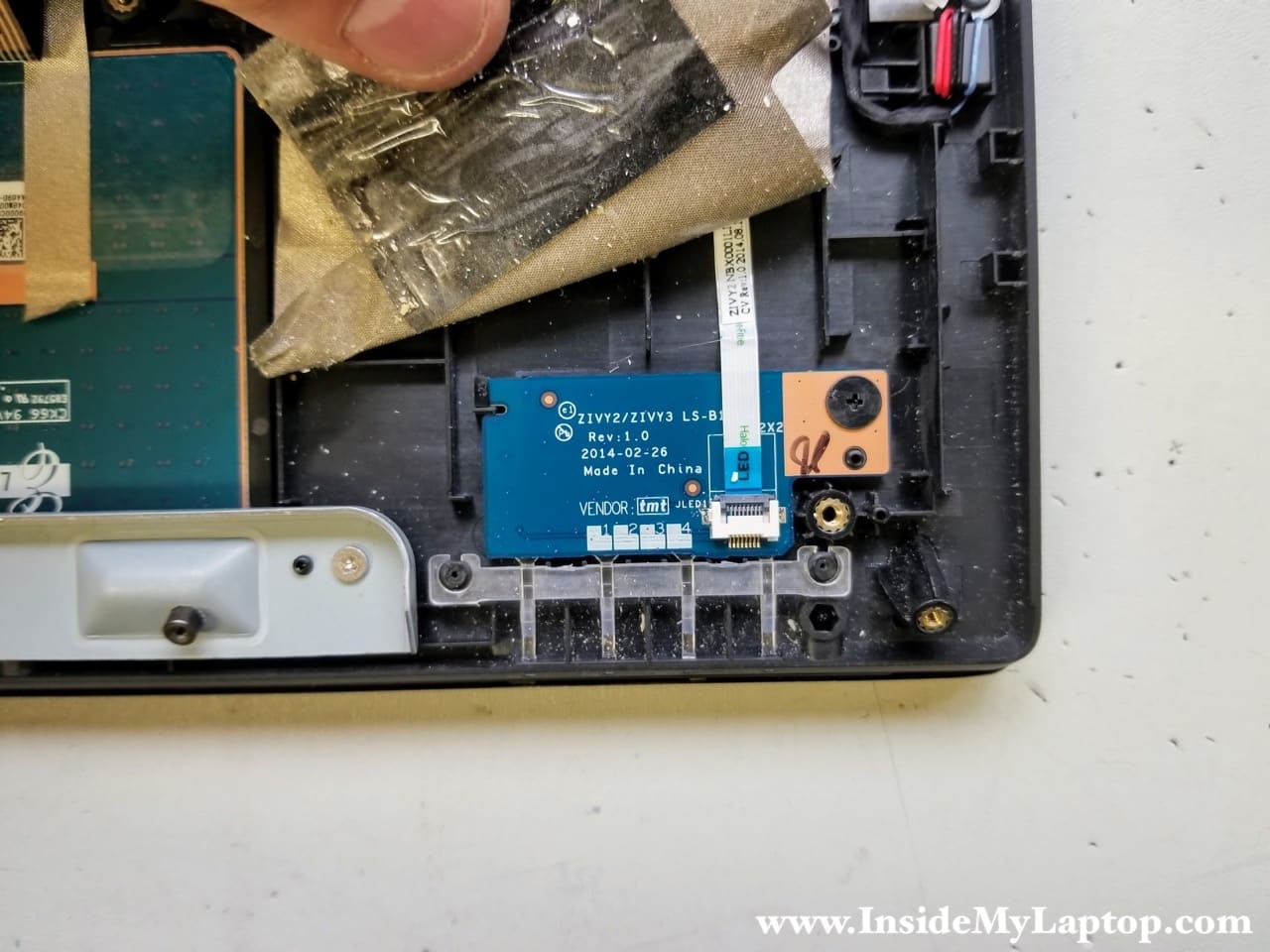
STEP 19.
The LED status board is hidden under the adhesive shielding. The LED board is secured by one screw and can be removed if necessary.
STEP 20.
The power button board also accessible and removable.
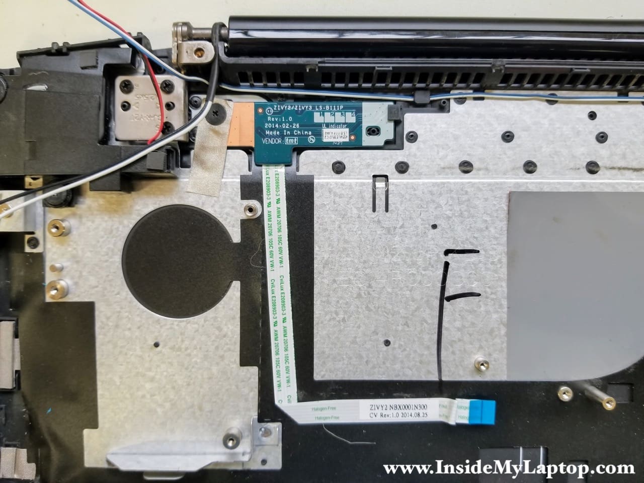
STEP 21.
The DC-IN power jack harness is routed along the side of the top case.
Part 2. Removing Lenovo Y50-70 LCD screen.
The LCD screen can be easily removed and replaced on these models.
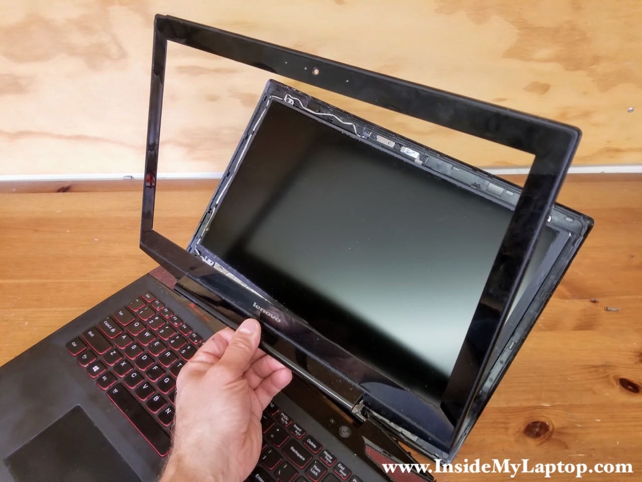
STEP 1.
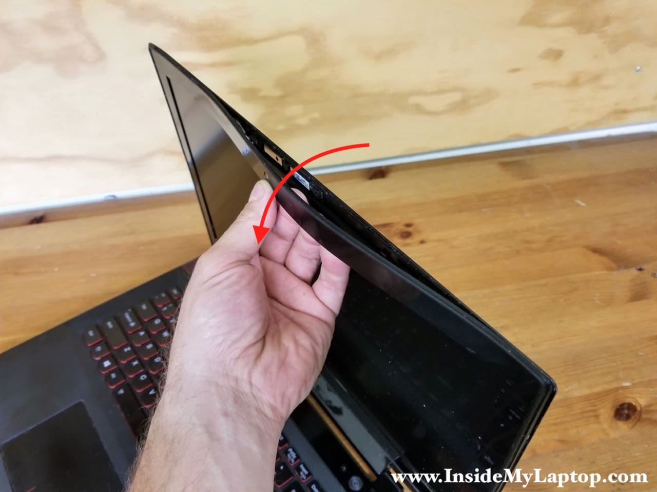
Start the display disassembly from the top side.
Insert your fingers between the front bezel and LCD screen and separate the bezel from the back cover.
STEP 2.
Continue removing the bezel on both sides of the display.
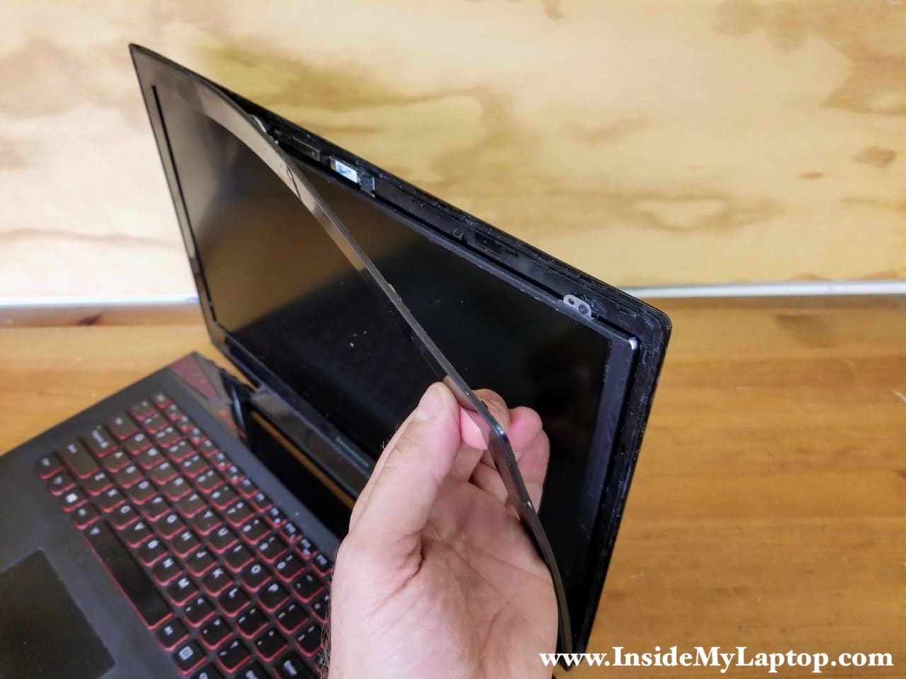
STEP 3.
Remove the front bezel from the display.
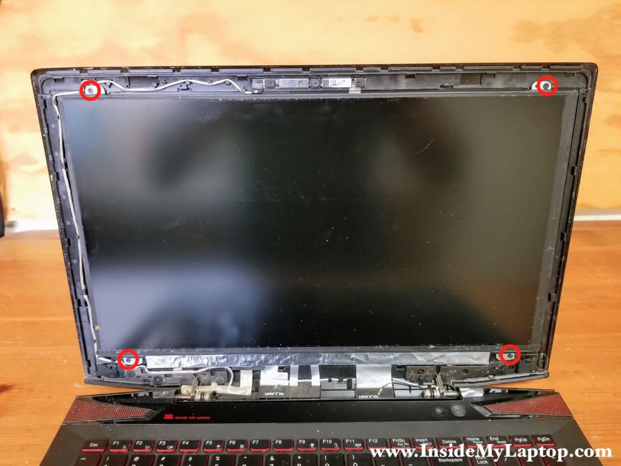
STEP 4.
Remove four screws attaching the LCD screen to the back cover.
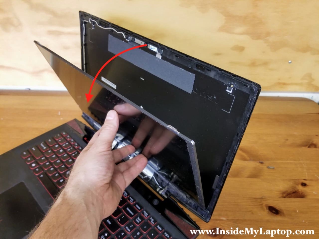
STEP 5.
Separate the LCD screen from the back cover.
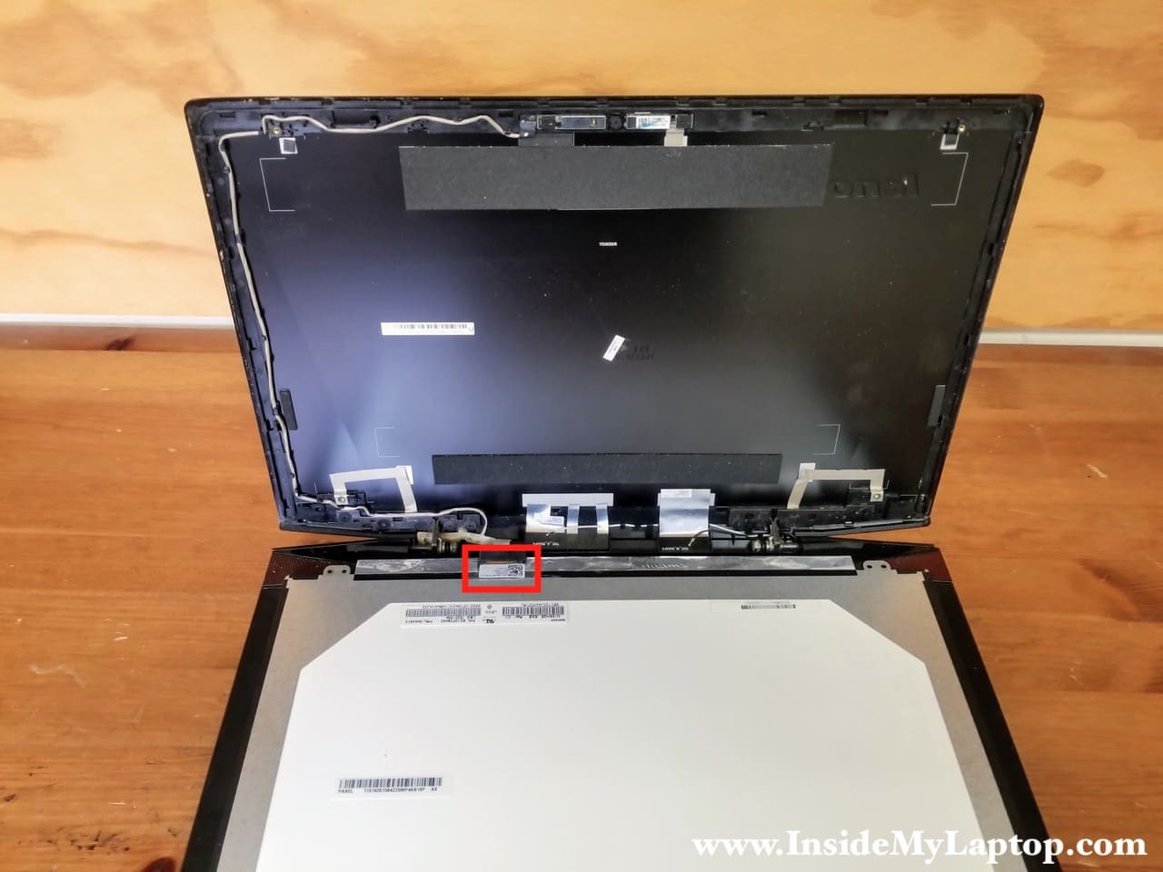
STEP 6.
Place the LCD screen the front side down on the keyboard.
Now you can access the video cable connector on the back.
STEP 7.
Peel of the clear tape securing the connection.
Unplug the video cable from the LCD screen.

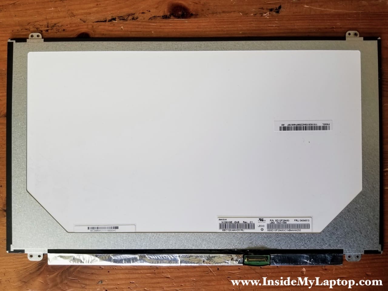
Now you can replace the LCD screen with a new one.
You can find a new screen using the model number or Lenovo FRU number printed on the back.
In my case the model number: N156HGE-EAB Rev. C1 and Lenovo FRU part number: 04X4813
Elia
Hi! A small piece of magnet fell off while disassembling a lenovo y50-70 for keyboard replacement. I guess it’s needed by the lid closure sensor but I cannot figure out where it was positioned. Any ideas?
Evelyn
@ Elia ^ that probably is from the upper case, screen bezel 🙂 there should be two tiny magnets, one on top and one on bottom. You should be able to google pics for where
Ibrahim
What is the harness that is aligned along the upper case of the laptop? Is it the camera. Because I tore mine in half by mistake?
IML Tech
If you are asking about the cable inside the display panel, along the left side of the LCD screen, it’s the webcam cable.
Ibrahim
Is there a replacement steps anywhere online?
IML Tech
The webcam cable is a part of the display cable harness. It’s necessary to separate the display panel from the laptop base in order to replace the cable/harness. You’ll have to disassemble the laptop as shown in the step 18. After that you can remove screws from the display hinges and separate the display from the base.
When the display is removed, you take it apart and replace the display harness with the webcam cable.