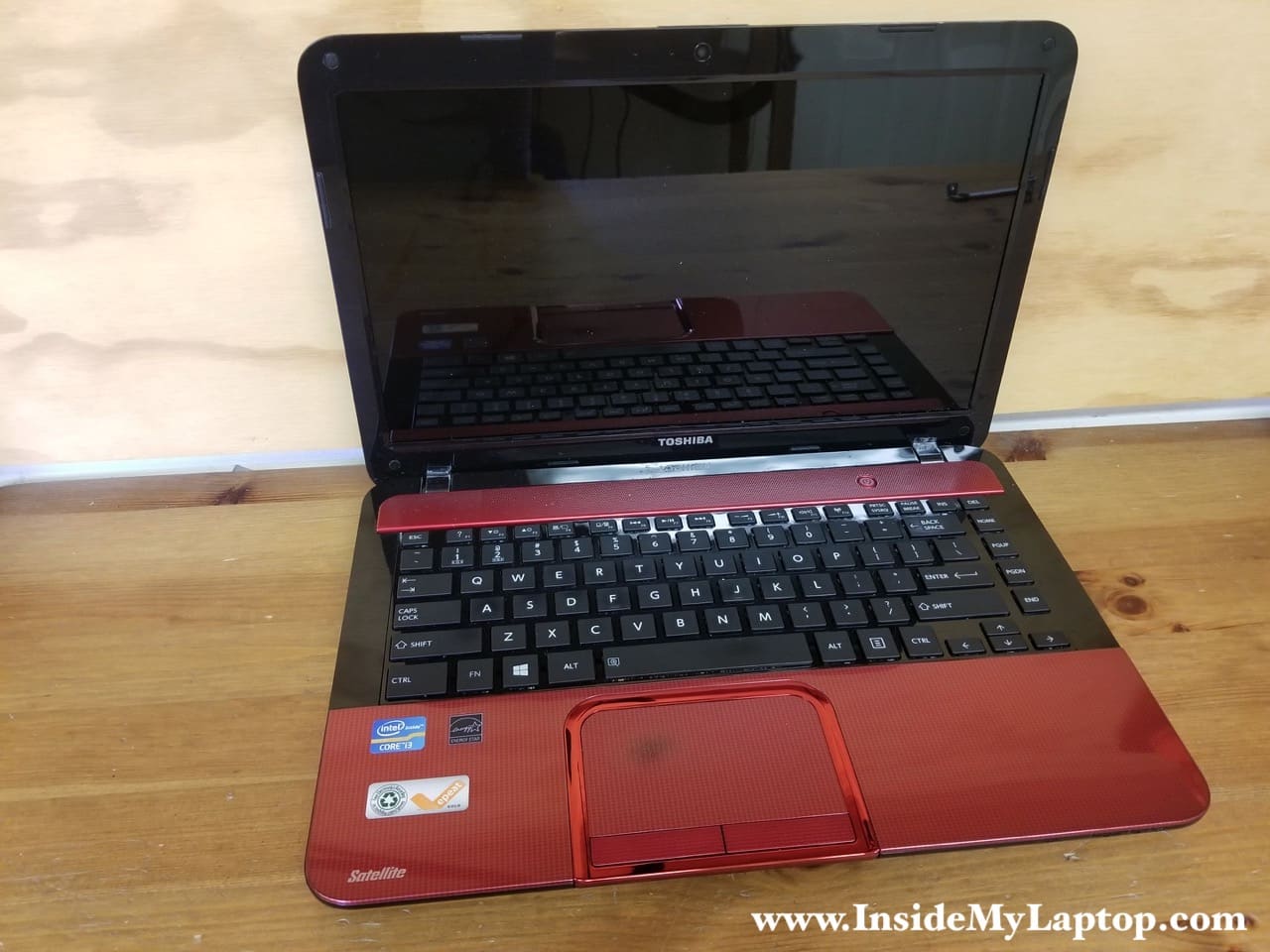
In this guide I will be taking apart a Toshiba Satellite L840 laptop.
Toshiba has the same user’s manual for the following models:
Satellite and Satellite Pro L840/L840D, L845/L845D, M840/M845, L800/L800D, M800/M805, C840/C840D, C800/C800D, C805/C805D, C845/C845D
I assume that all disassembly steps in this guide can be used for taking apart all these models. The guide has two parts: laptop body disassembly and screen removal. Both parts are independent from each other.
Part1. Laptop body disassembly.
STEP 1.
Unlock and remove the battery.
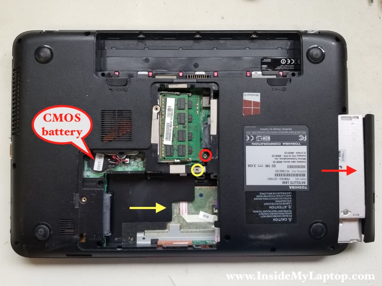
Remove two screws securing the service hatch. Remove the hatch.

STEP 2.
Remove one screw (red circle) securing the CD/DVD drive and pull the drive out.
Remove one screw (yellow) securing the hard drive caddy. Slide the hard drive to the right to disconnect it from the motherboard. Remove the hard drive (already removed on my picture).
Installing a 2.5″ SATA solid state drive instead of the regular hard drive will improve laptop performance significantly.
Also, under the service hatch you can access both memory modules and CMOS battery.
This laptop can handle up to 16GB (2x8GB) DDR3-12800 SODIMM RAM modules.
STEP 3.
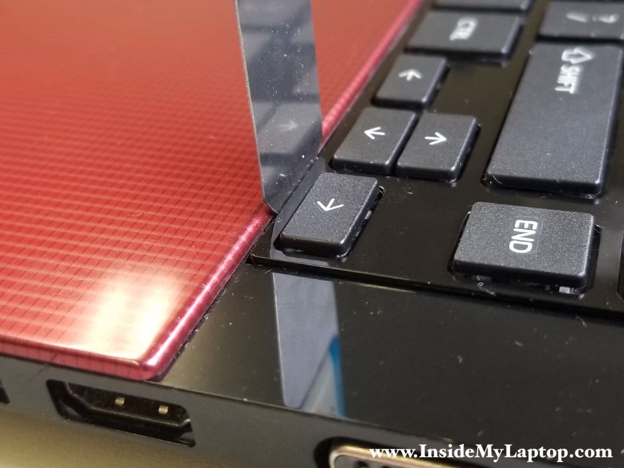
For the keyboard removal you’ll need a thin metal case opener or any other similar tool.
Insert the case opener between the keyboard and the palmrest.
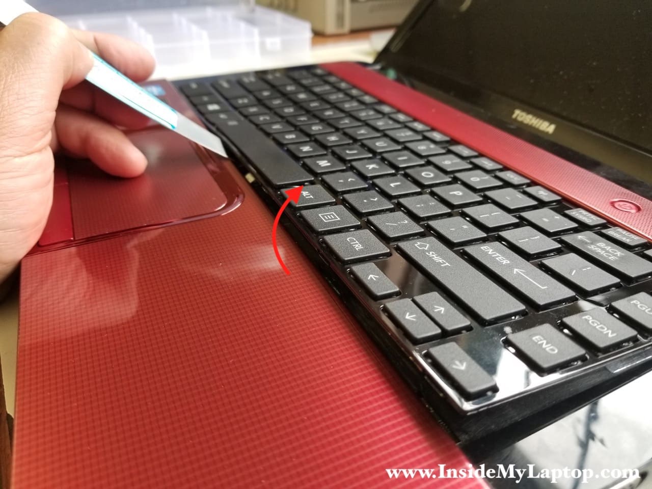
STEP 4.
Gently pry the keyboard up and away from the palmrest.

STEP 5.
Continue separating the keyboard from the palmrest.
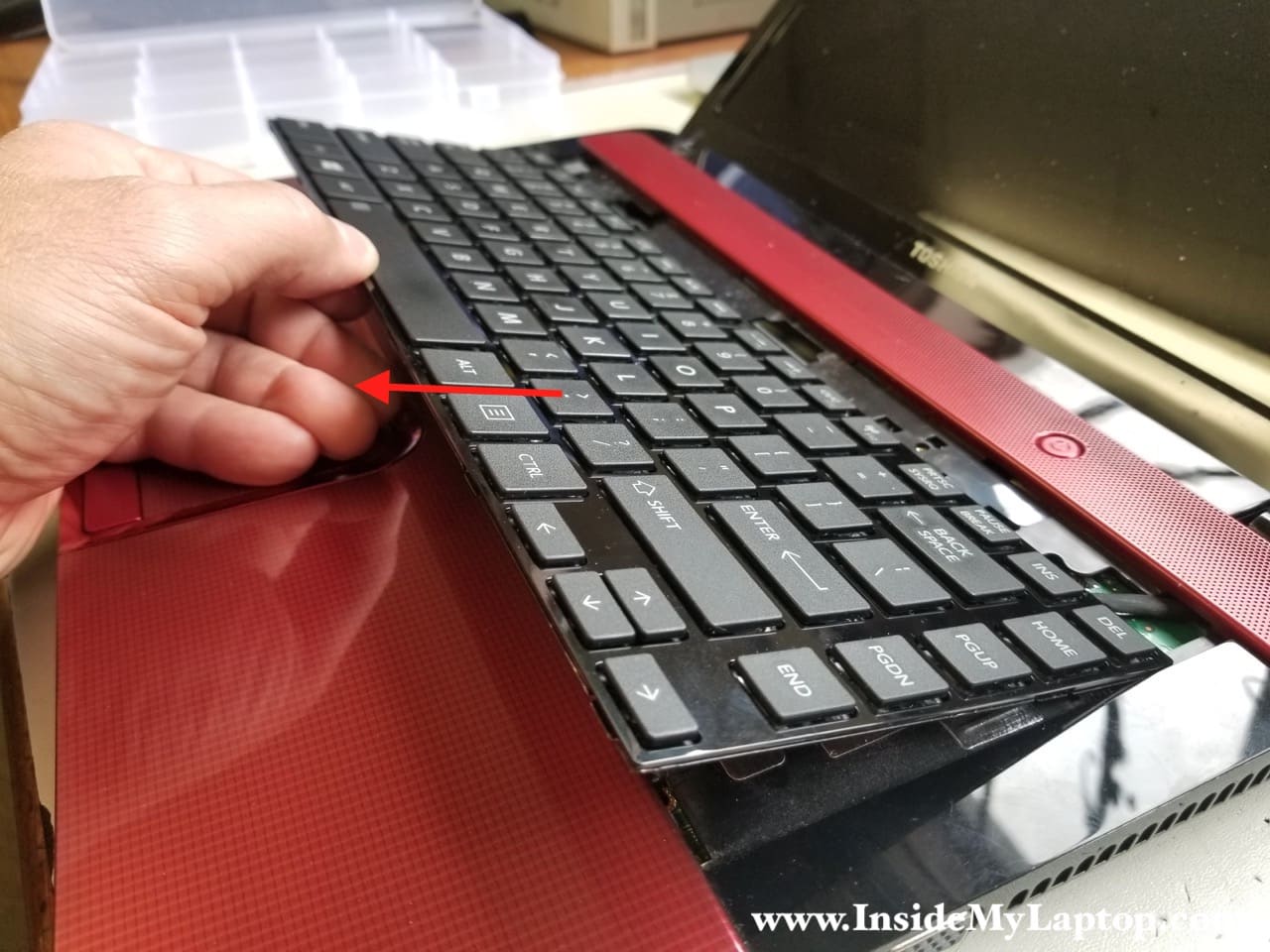
STEP 6.
Pull the keyboard away from the display to disengage it from the top cover.
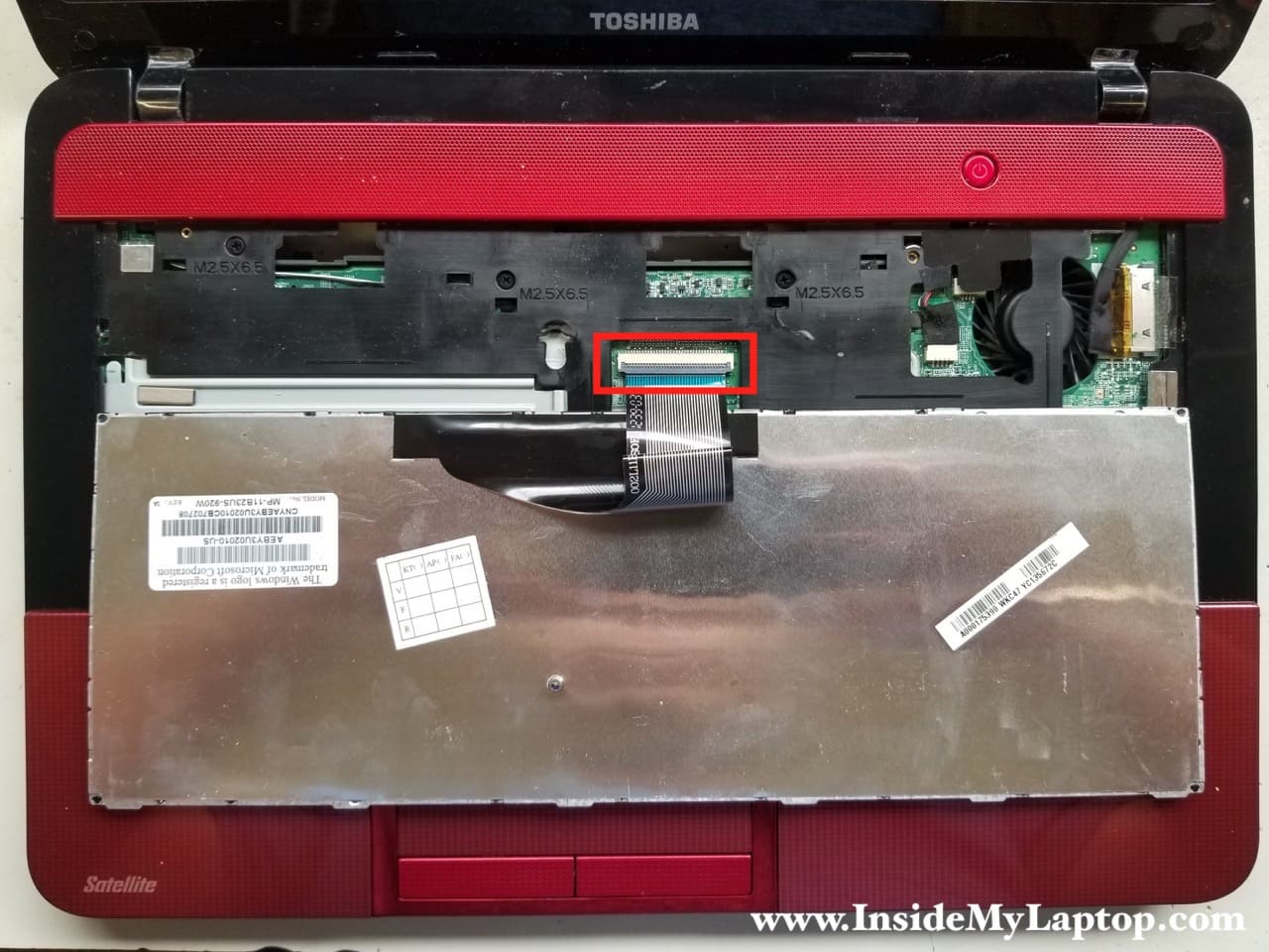
STEP 7.
Place the keyboard upside down on the palmrest to access the cable connector underneath.
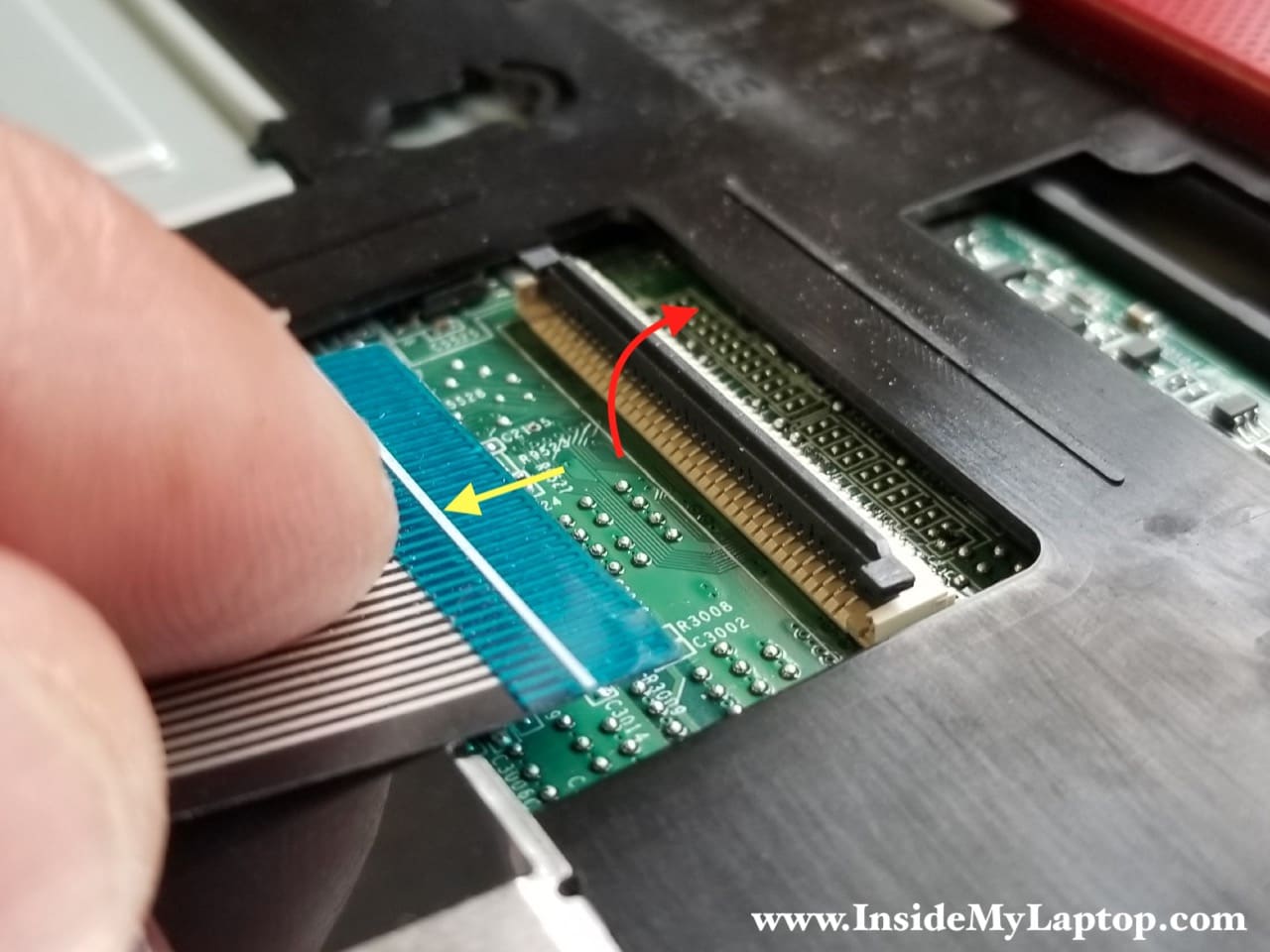
STEP 8.
Unlock the connector by lifting up the locking tab (red arrow).
Release the cable and remove the keyboard.
STEP 9.
Remove four screw from the top case.
Disconnect the follwoing cables I color coded:
- Touchpad cable (red)
- Speaker cable (orange)
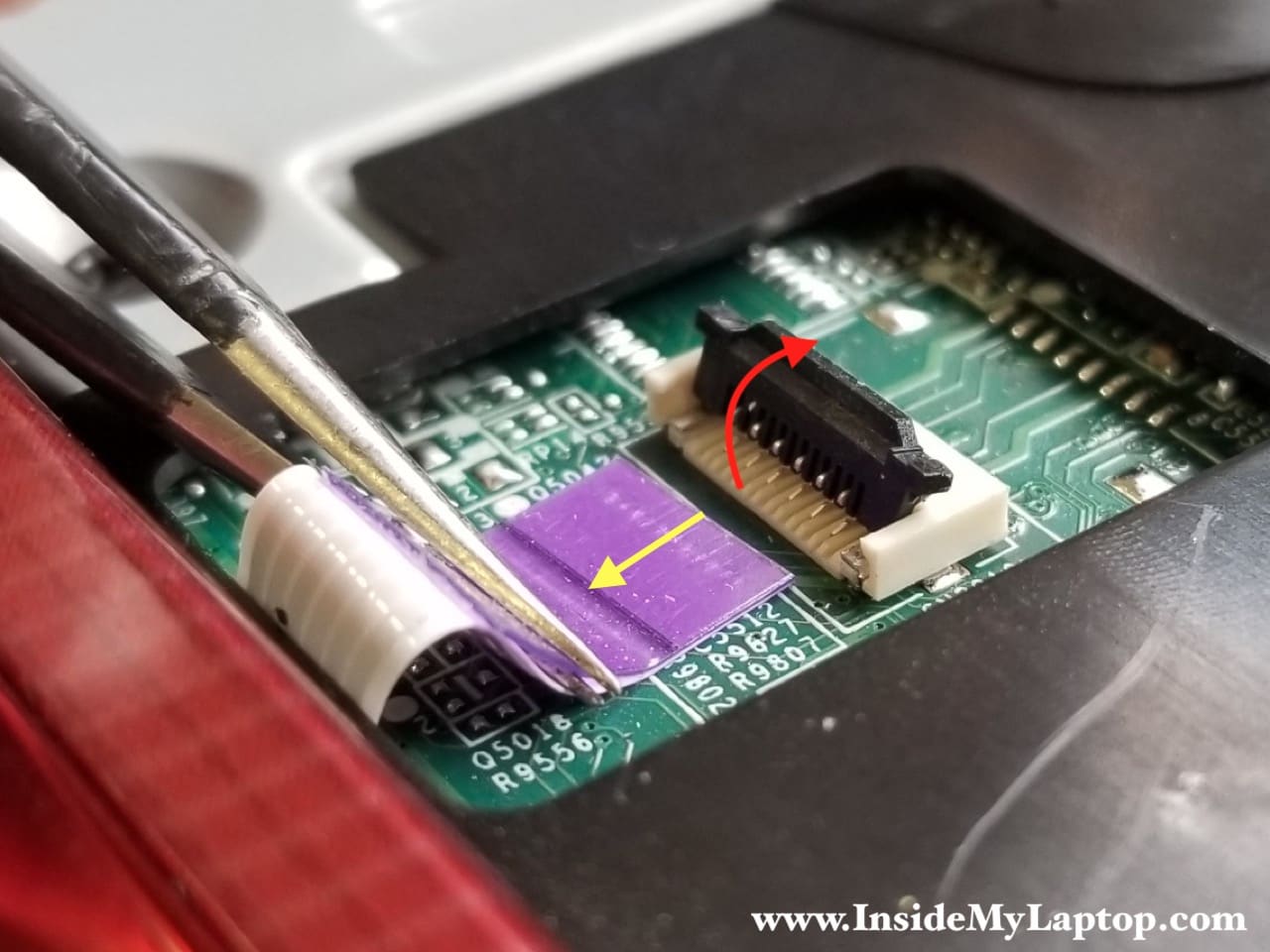
- Power button cable (green)
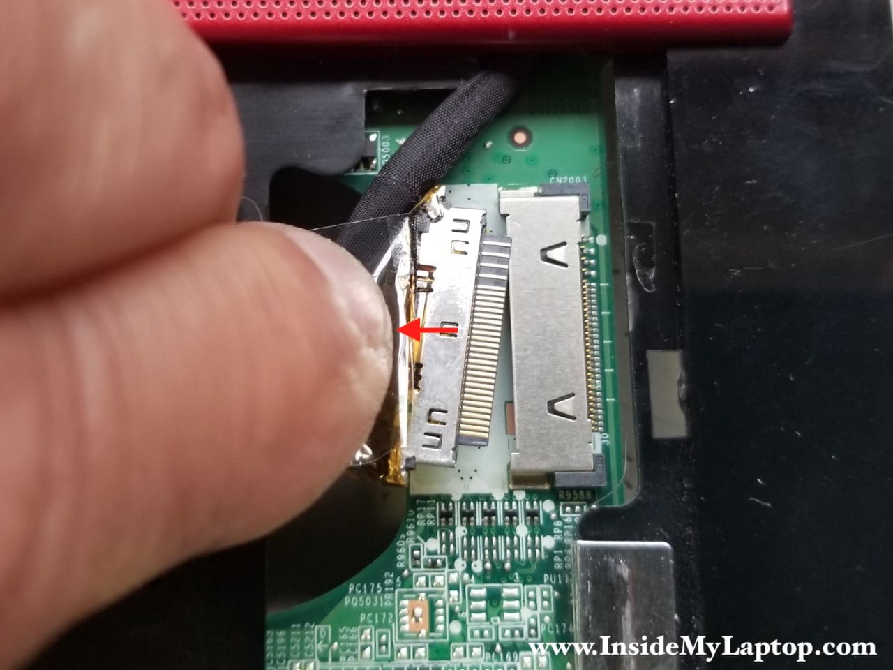
- Display video cable (yellow)
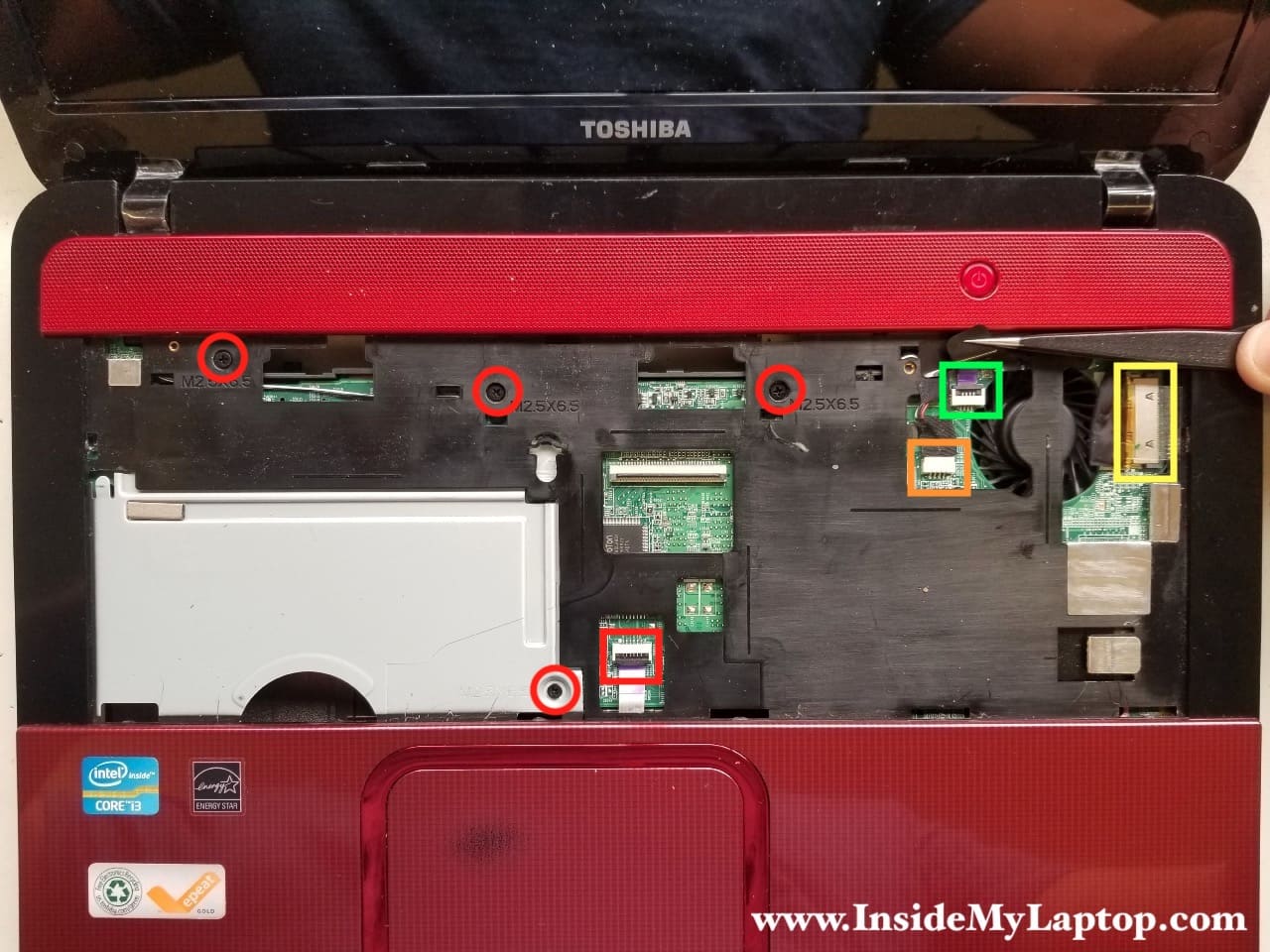
Here’s how to release flat cables (red and green). Unlock the connector (red arrow) and pull the cable out.
Peel off sticky tape securing the connection (yellow) and pul the display video cable out.
STEP 10.
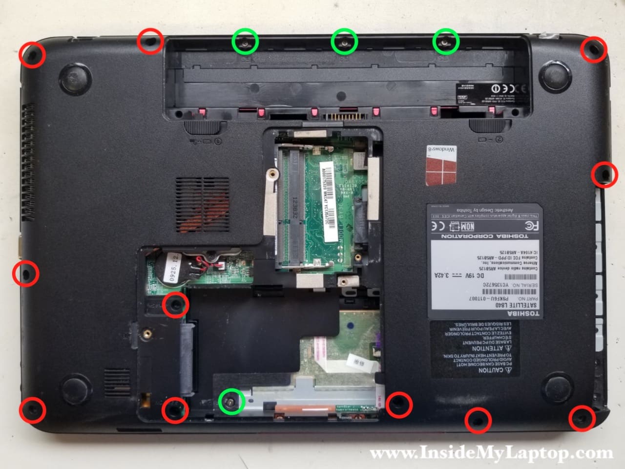
Remove all screws from the bottom case. “Green” screws are shorter than “red” screws.
STEP 11.
Remove the bottom case.
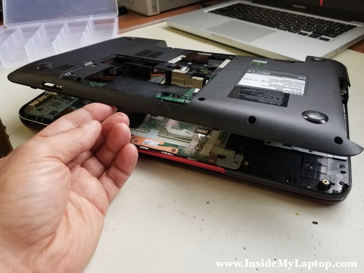
Now we can access all internal laptop components.
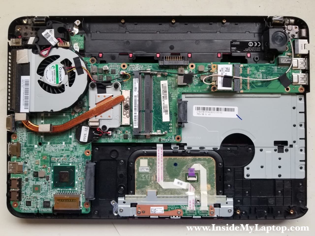
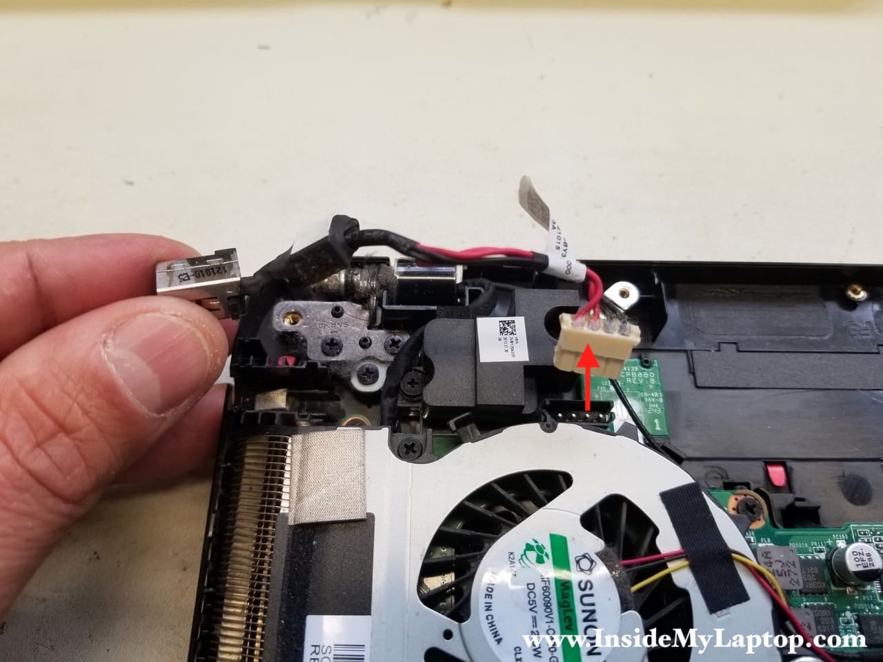
STEP 12.
Disconnect the DC jack cable from the motherboard and remove it.
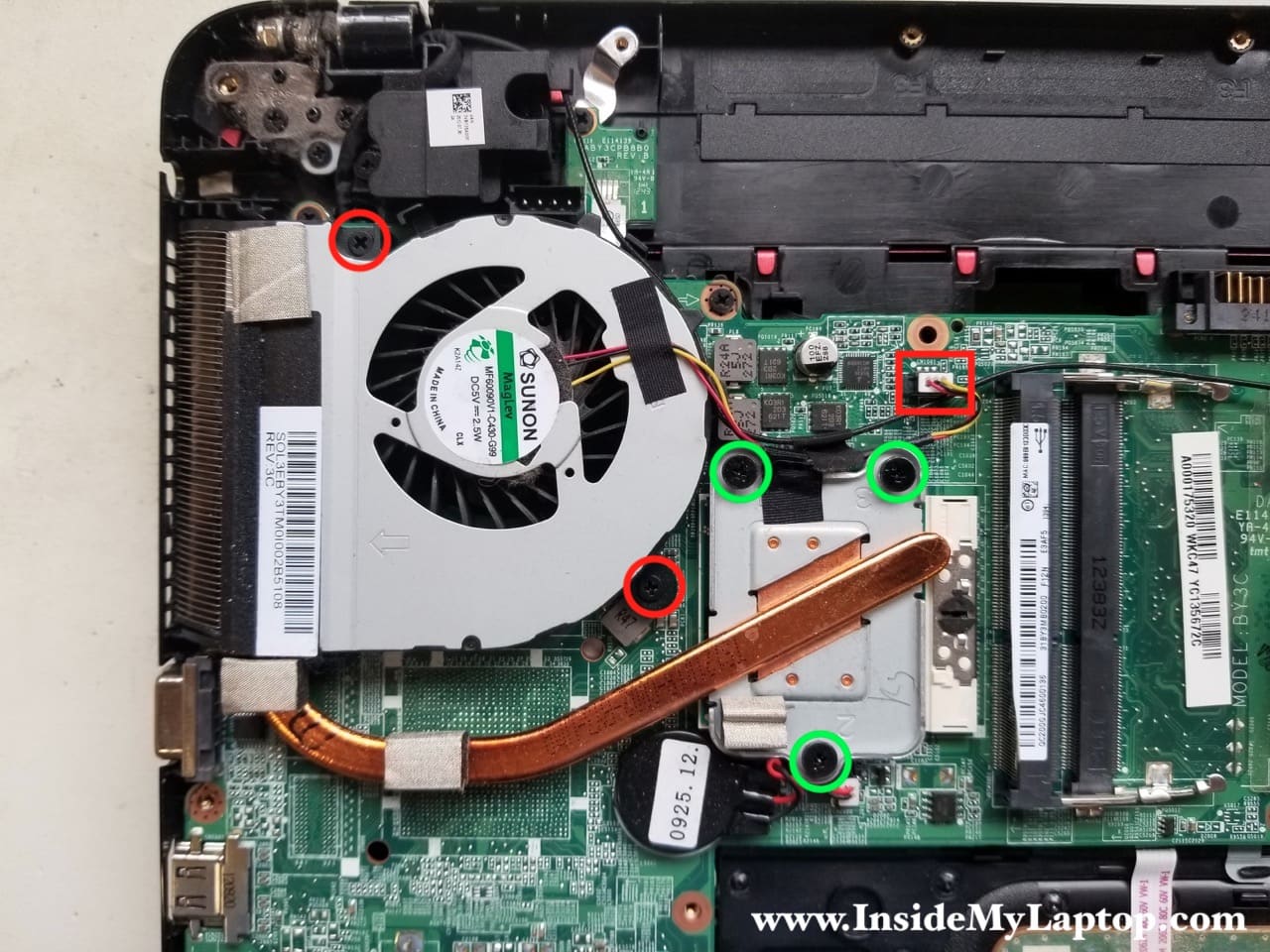
STEP 13.
Remove two screws (red) securing the fan. Loosen three screws (green) securing the heatsink.
Disconnect the fan cable.
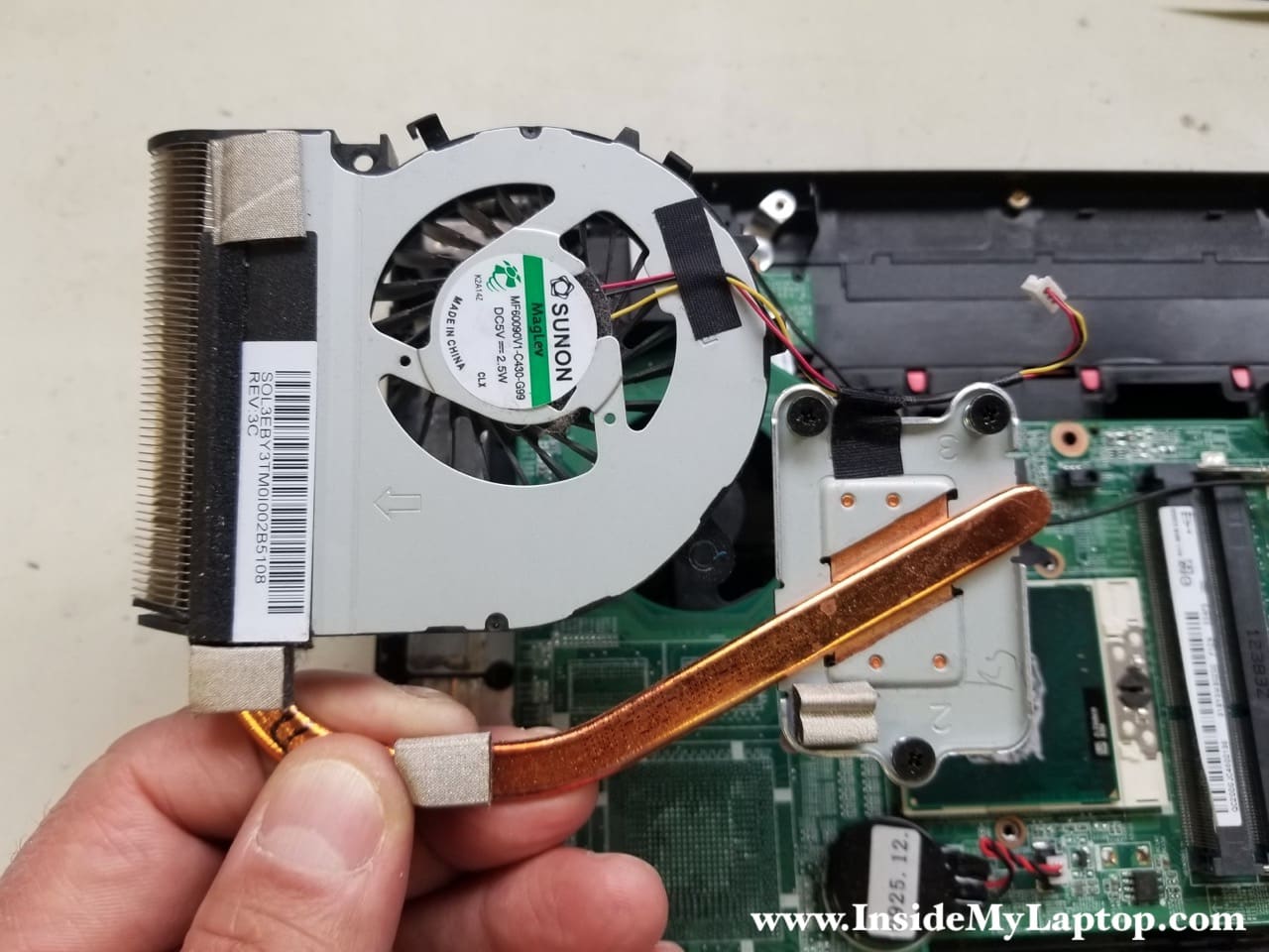
STEP 14.
Remove the cooling module. While removing it, pay attention to how the black wireless antenna cable is routed on the side of the fan.
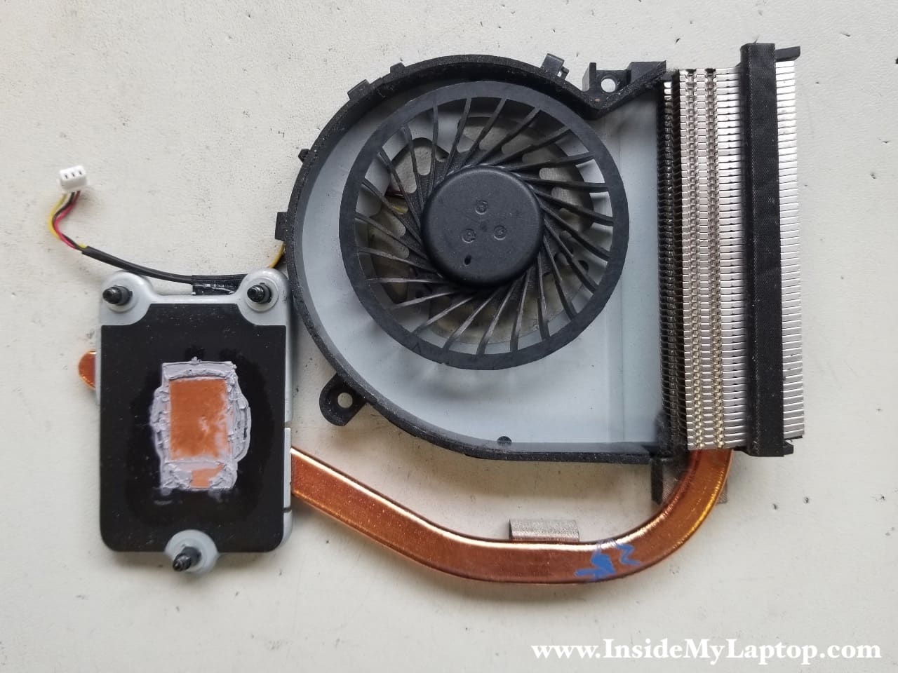
Here’s the other side of the cooling module.
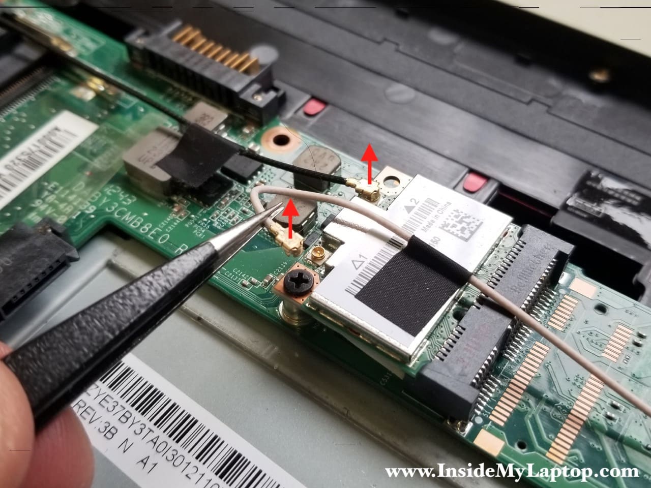
STEP 15.
Disconnect both Wi-Fi antenna cables from the wireless card.
The wireless antennas attached to the motherboard by electrical tape. Pay attention how both antennas are routed on the motherboard.
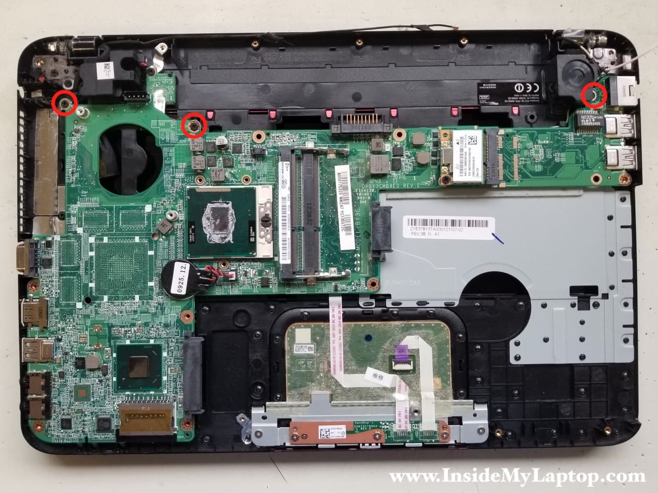
STEP 16.
Remove three screws securing the motherboard.
STEP 17.
Lift up the right side of the motherboard and remove it from the top case.
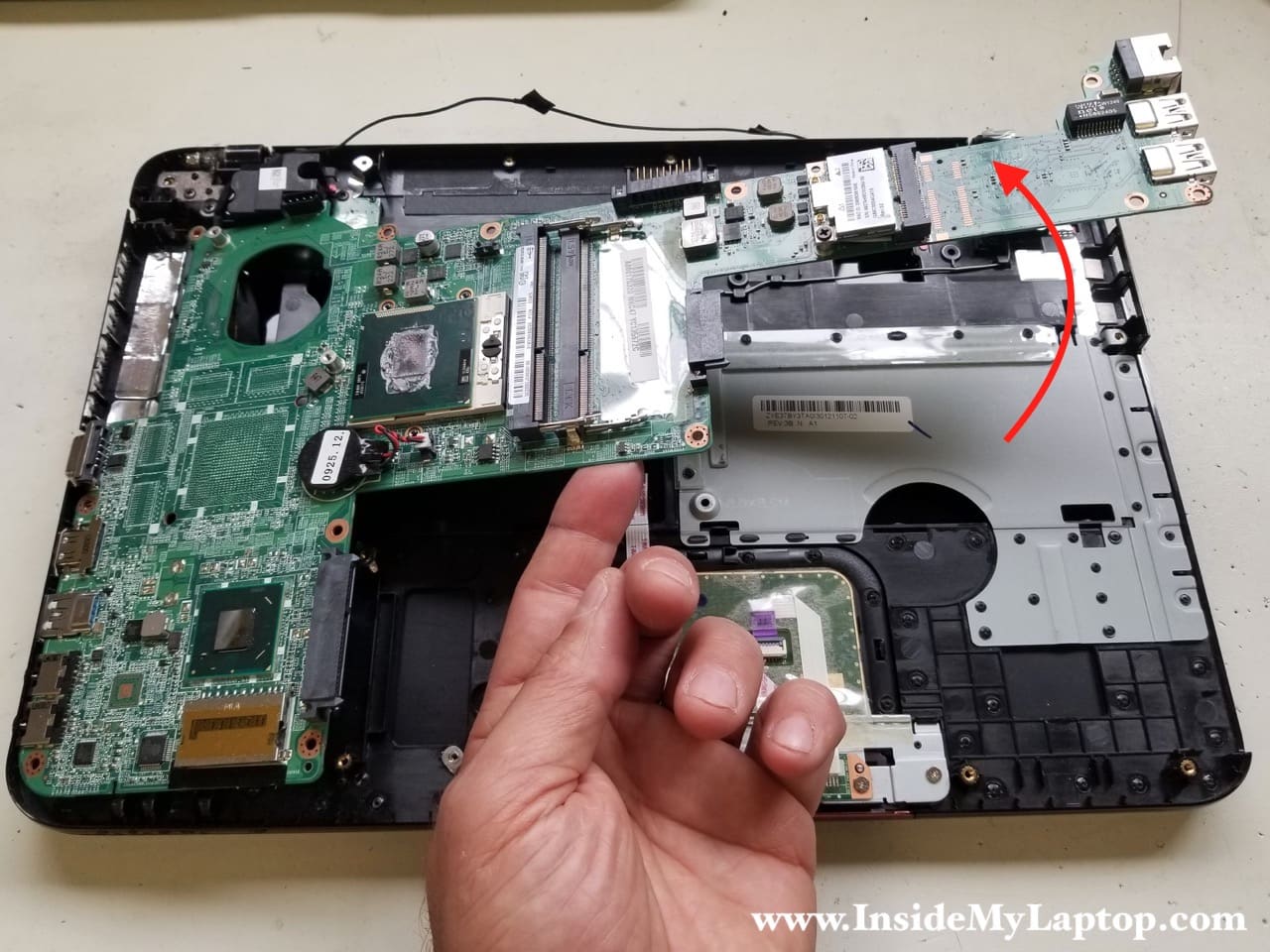
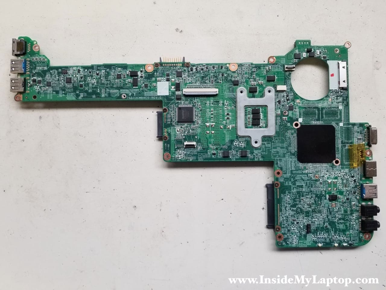
Here’s the other side of the board.
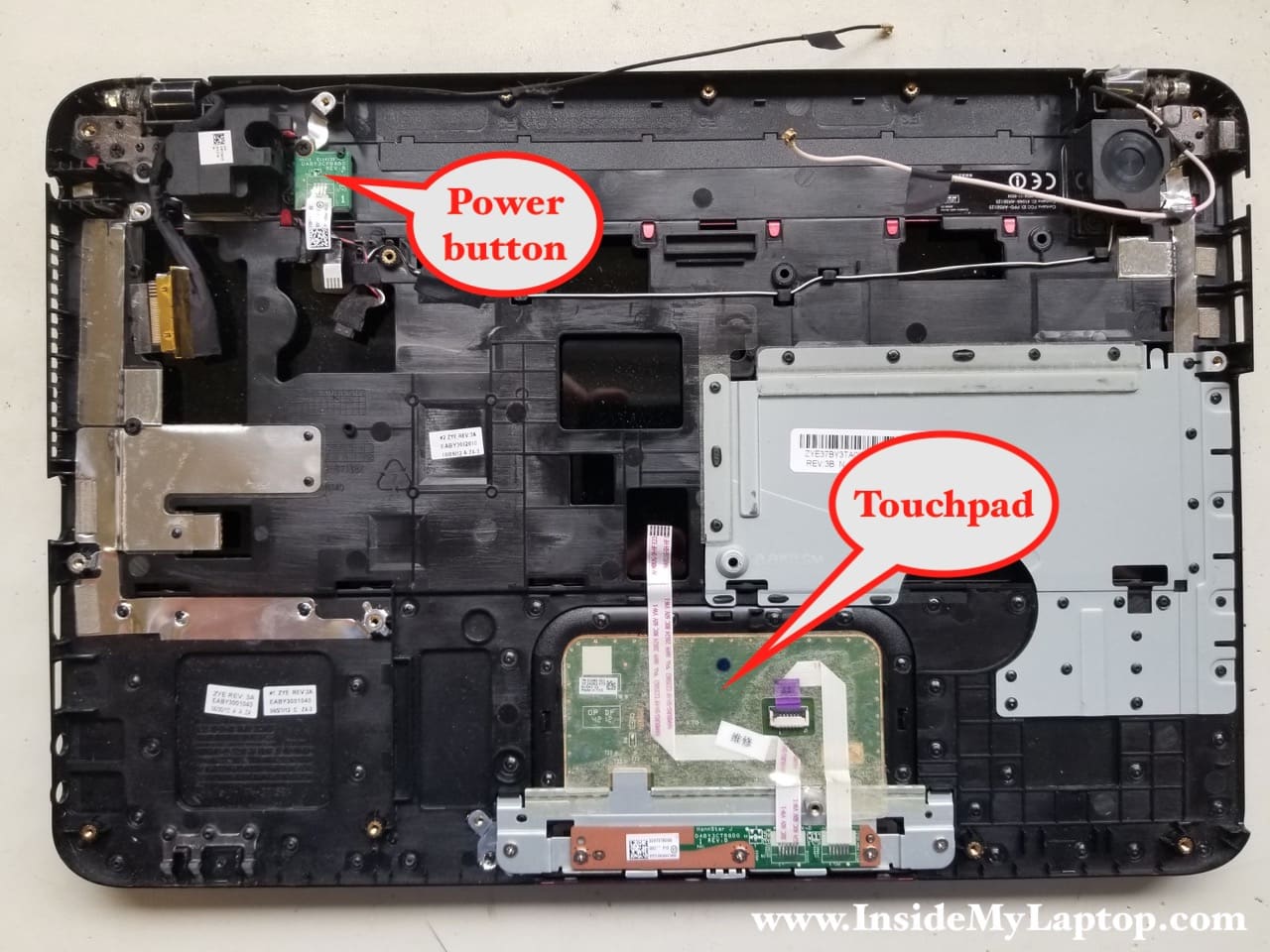
The power button board and the touchpad are still attached to the top case. They can be easily removed if necessary.
Part2. Laptop screen removal.
As I mentioned earlier, this part of the guide is independent from the first part. Don’t forget to remove the battery before taking apart the display assembly.
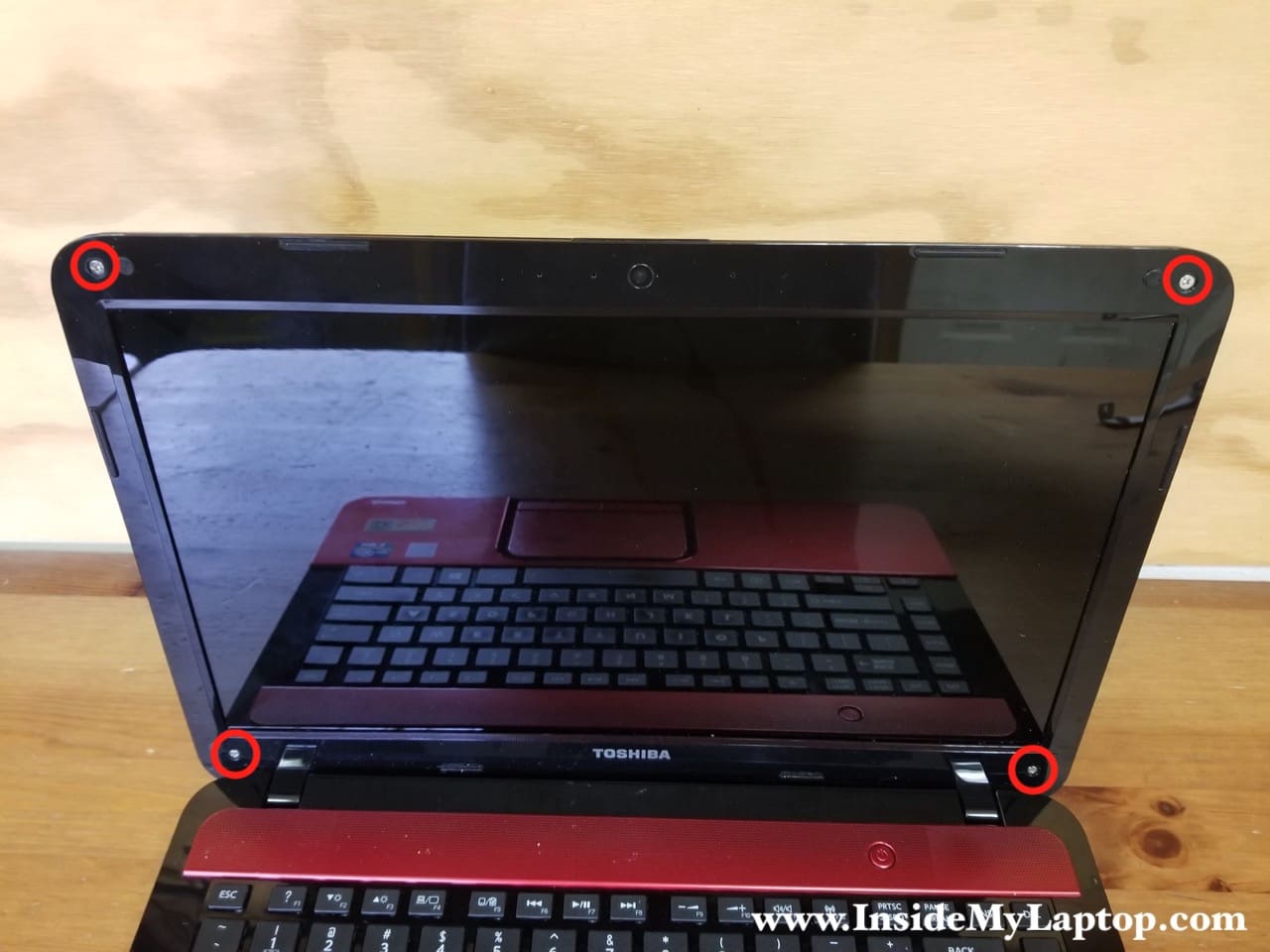
STEP 18.
The display bezel is secured to the back cover by four hidden screws. One screw is located in each corner of the bezel under the decorative covers.
Remove the covers using needle nose tweezers and remove all four screws.
STEP 19.
Start separating the bezel from the back cover on the top. Use a plastic case cracker and your fingers.
Wiggle the bezel to unfasten it from the back cover.
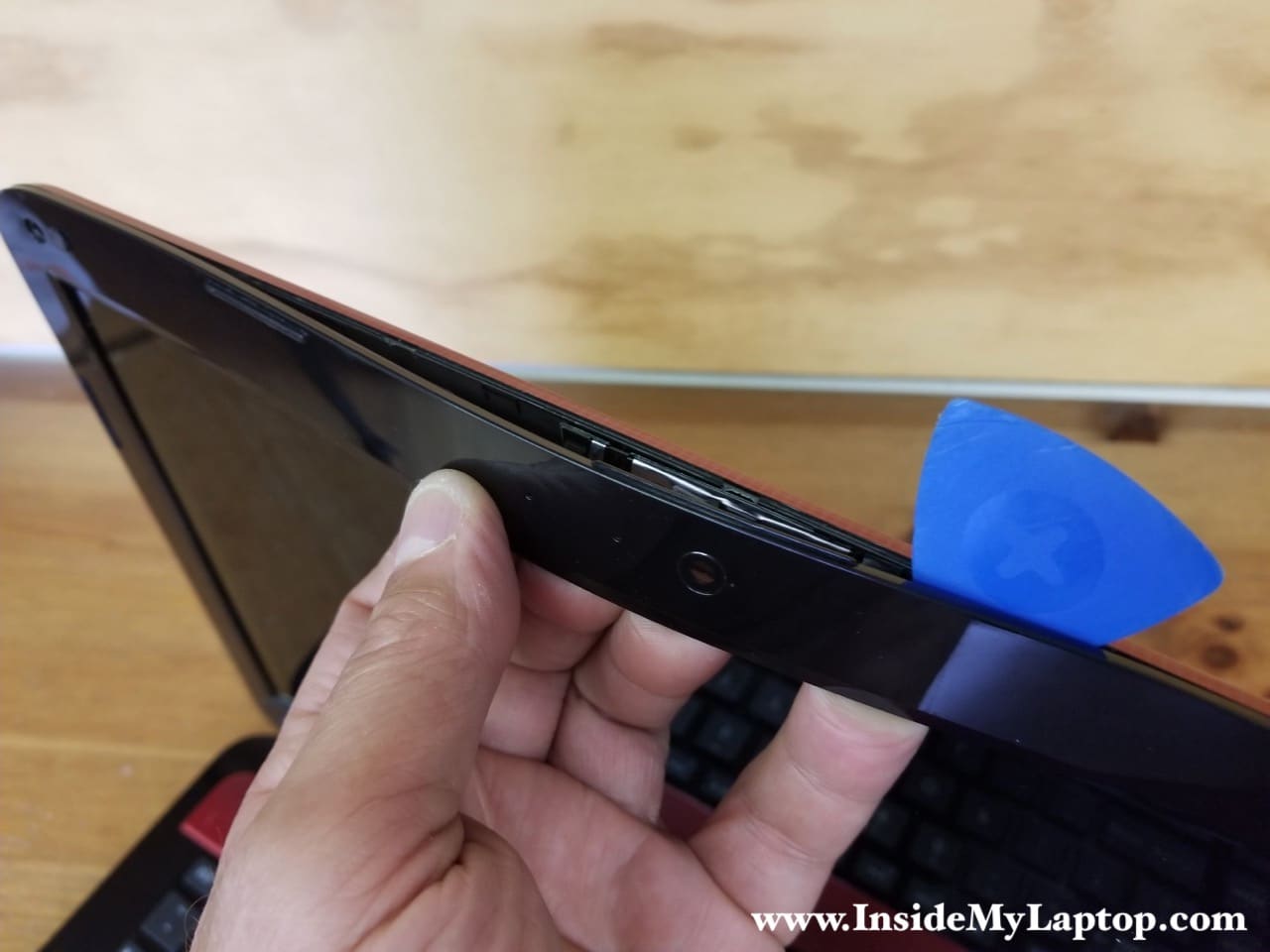
STEP 20.
Continue removing the bezel on both sides of the display and then move to the hinge area.
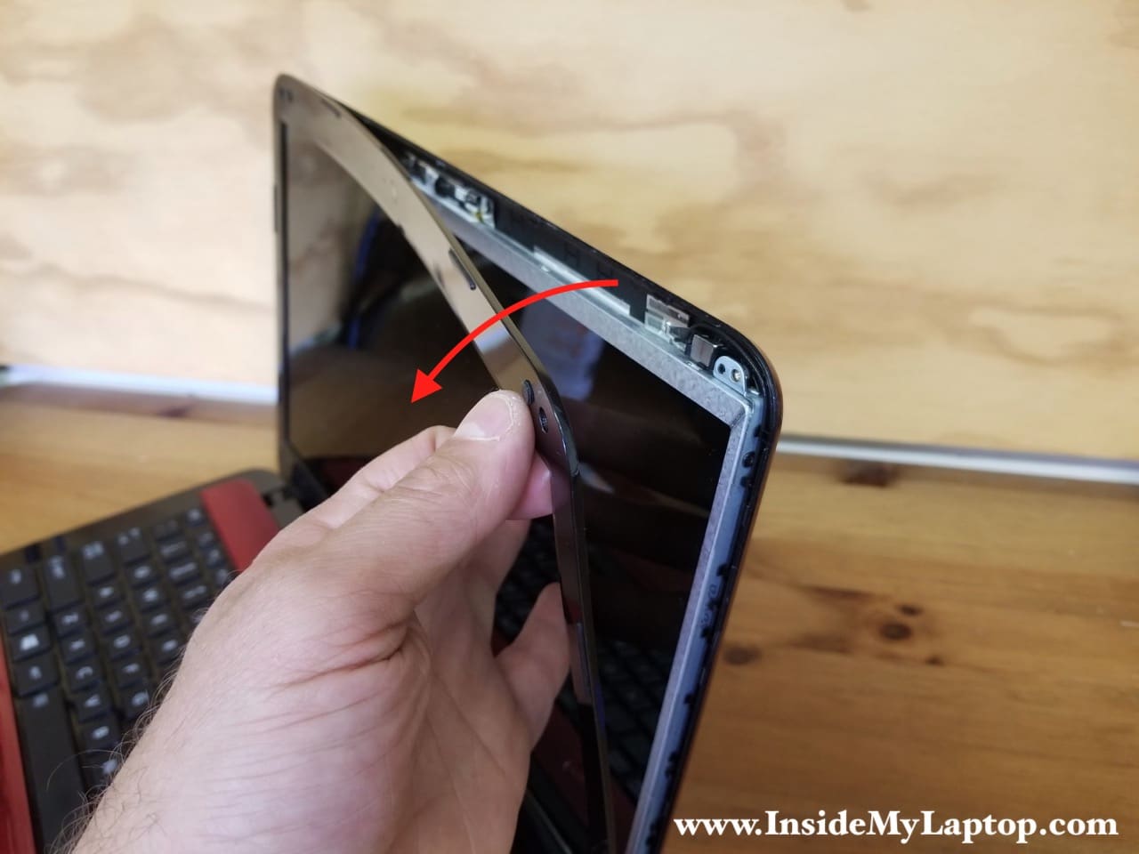
STEP 21.
Remove the bezel.
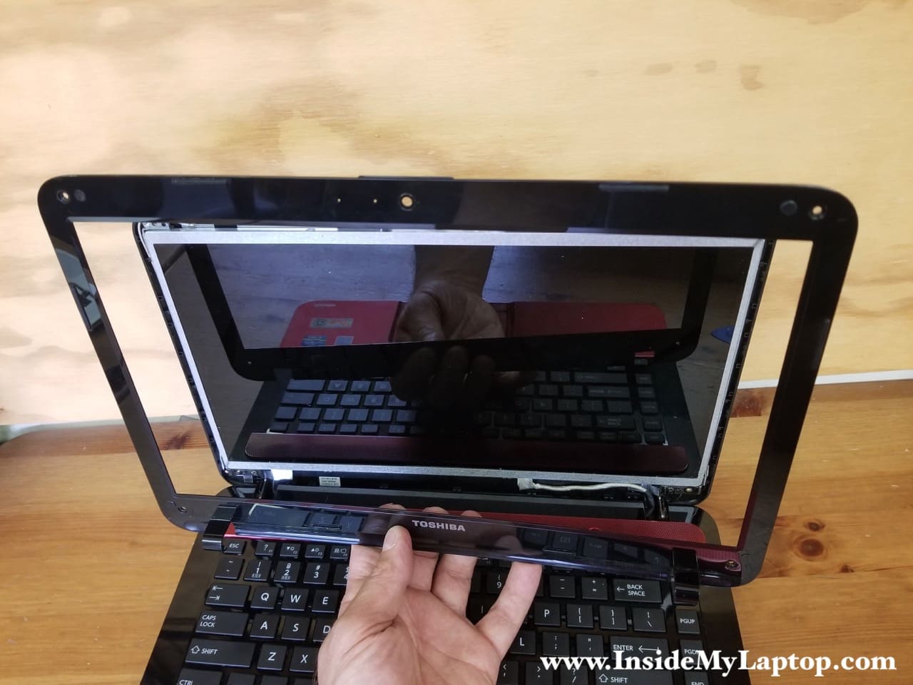
STEP 22.
The webcam cable is glued to the back of the LCD screen.
Disconnect the cable from the webcam before removing the screen.
STEP 23.
Remove two screws securing the hinges to the back cover.
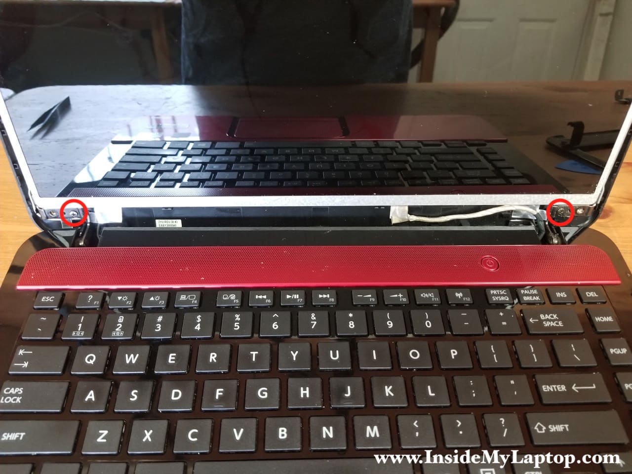
STEP 24.
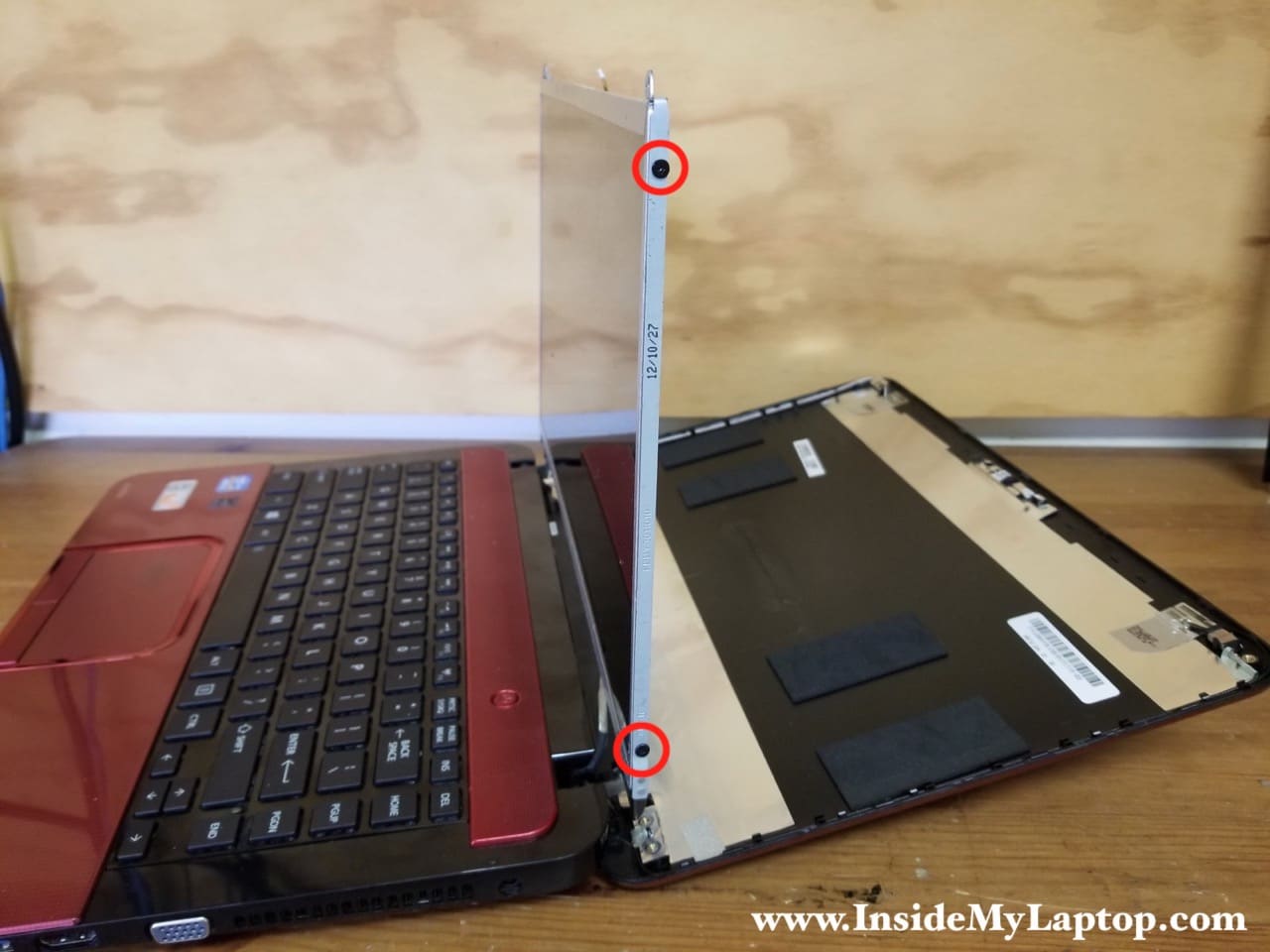
Separate the back cover from the screen and place it on the desk.
There are two screws securing the screen to the hinge bracket on each side. Remove them from each side.
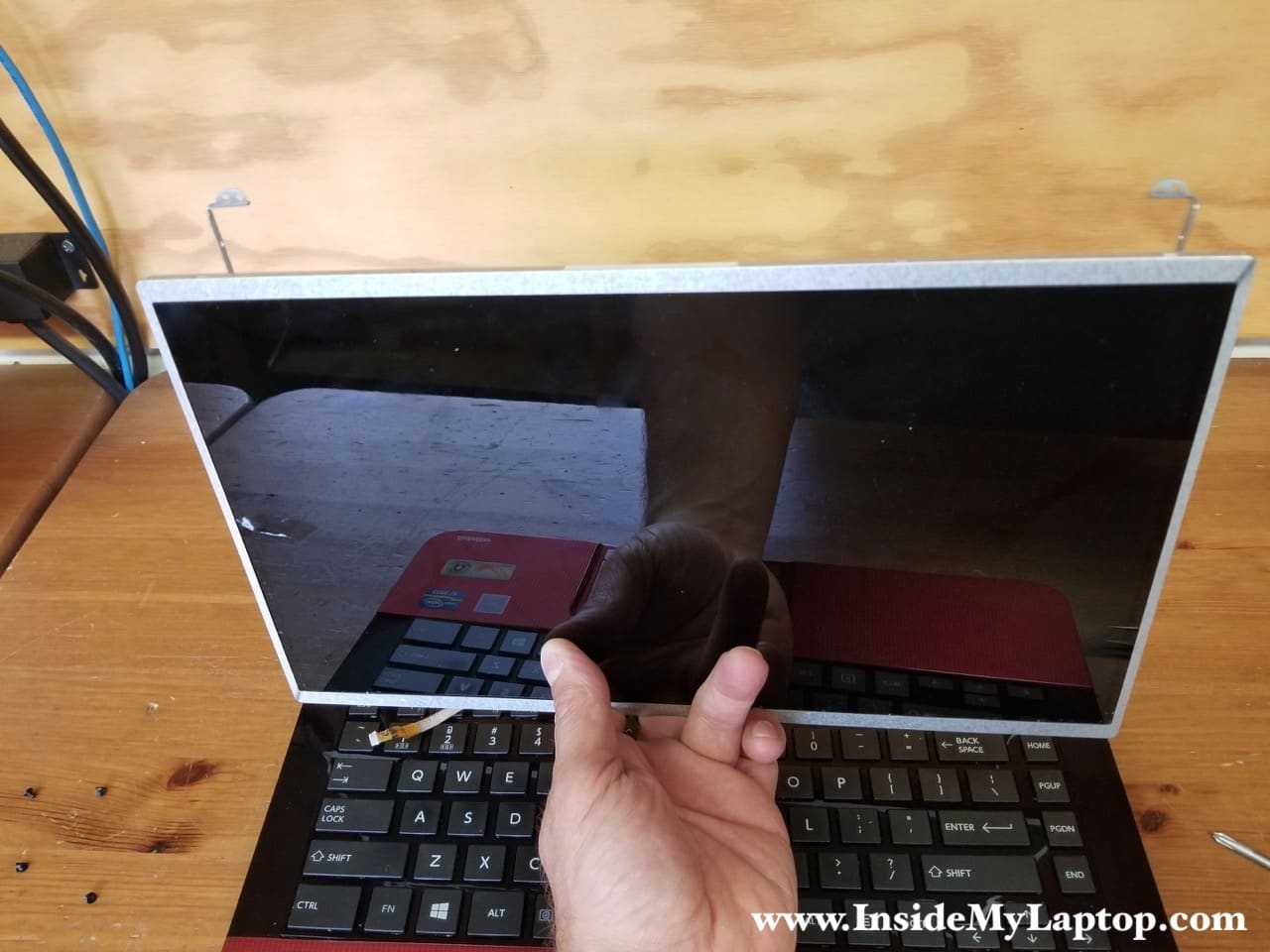
STEP 25.
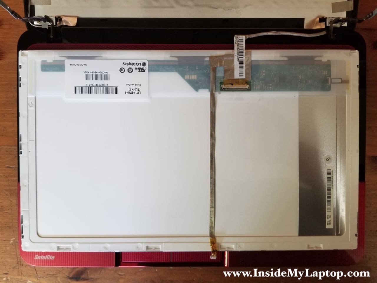
Place the LCD screen the front side down on the palmrest. Now you can access the cable.
STEP 26.
Unglue the webcam cable from the back of the screen.
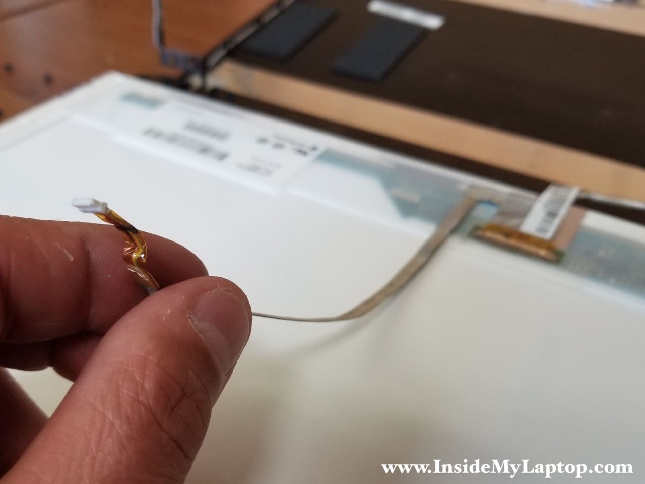
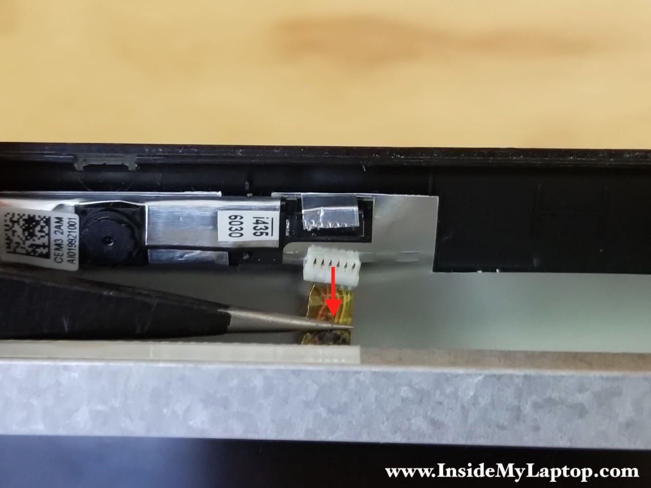
STEP 27.
Peel off clear tape securing the connection. Unplug the display video cable from the screen.
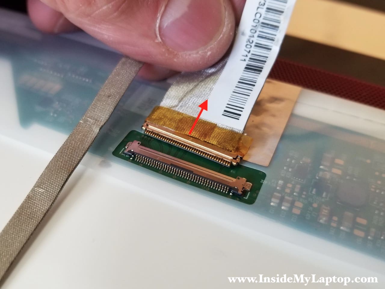
STEP 28.
Remove the LCD screen and replace it with a new one if necessary.
Replacement LCD screens model LP140WH4 (TL)(N1).