In this guide I show how to disassemble a VIZIO CT14 Ultrabook.
I’m going through the disassembly process in order to replace failed DC power jack. It looks like the DC jack is easily accessible under the cover but there is a trick.
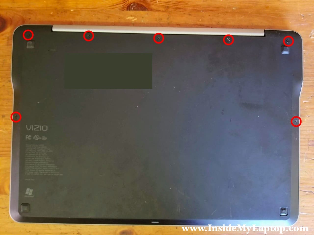
STEP 1.
Remove seven Torx5 screws from the bottom cover.
STEP 2.
Start lifting up the bottom from the display hinge side. Separate the cover completely and remove it.

STEP 3.
Remove five silver screws securing the battery.

STEP 4.
Disconnect the battery from the motherboard and remove it.

If you need a new battery, you can find a replacement using the model number from the original one. VIZIO CT14 battery model number: SQU-1107.

STEP 5.
Remove two screw securing the solid state drive.

STEP 6.
Pull the solid state drive out of the slot.

STEP 7.
Remove three screws securing the cooling fan. Disconnect fan cable from the motherboard.

STEP 8.
Remove the fan.

STEP 9.
Remove one screw securing the wireless card.
Disconnect both antenna cables from the card.

STEP 10.
Remove the wireless card.

STEP 11.
In order to separate the display panel from the palmrest assembly it is necessary to remove screws from both display hinges and unplug the display video cable from the motherboard.
In is not necessary to remove the display in order to access the DC jack. I just want to show how you can remove it from the laptop if needed.

Pull the display video connector up to disconnect it from the motherboard.

STEP 12.
Place the laptop upside down with the display open on the edge of your desk.
Remove three screws from each display hinge.

STEP 13.
Now you can remove the display panel completely.

STEP 14.
The DC power jack seams to be easily accessible but it cannot be removed until you remove the motherboard. The DC power jack mounting bracket secured under the motherboard.

STEP 15.
Remove six screws securing the motherboard.
Disconnect the front LED cable (green square), touchpad cable (orange square), keyboard cable (blue square), DC power jack cable (pink square) and speakers cable (red square).

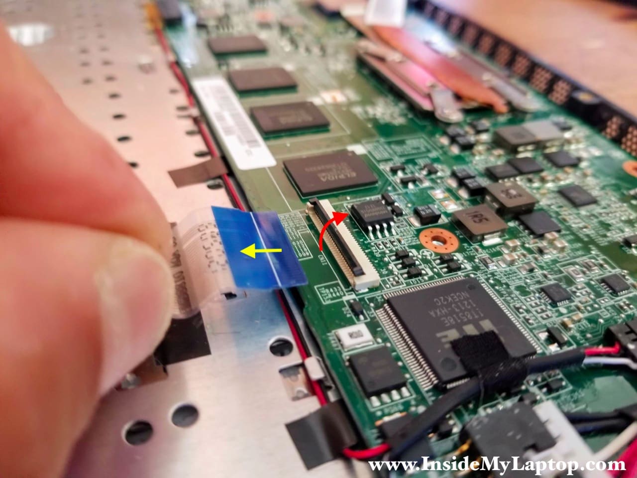
Here’s how to disconnect flat cables.
Unlock the connector first by lifting up the locking tab (red arrow). After that pull the cable out (yellow arrow).
The DC power jack and speaker cables can be simply unplugged.

STEP 16.
With all screws removed and cables disconnected you can start removing the motherboard from the palmrest assembly.

Here’s a photo of the other side of the motherboard just in case if you need it.

STEP 17.
Now we can remove one screw securing the DC power jack bracket and pull the jack out.

VIZIO CT14 laptop has the keyboard and trackpad permanently attached to the palmrest. They cannot be easily removed.
