This guide will help you to disassemble a Dell Latitude E7470 (regulatory model P61G) laptop. I’m taking apart the base assembly in order to access and replace the keyboard.
Some of the design features of Dell Latitude E7470:
– There are two memory slots on the motherboard.
– The keyboard is not permanently attached to the top case and it’s replaceable.
– SSD and RAM slots are easily accessible for upgrades.
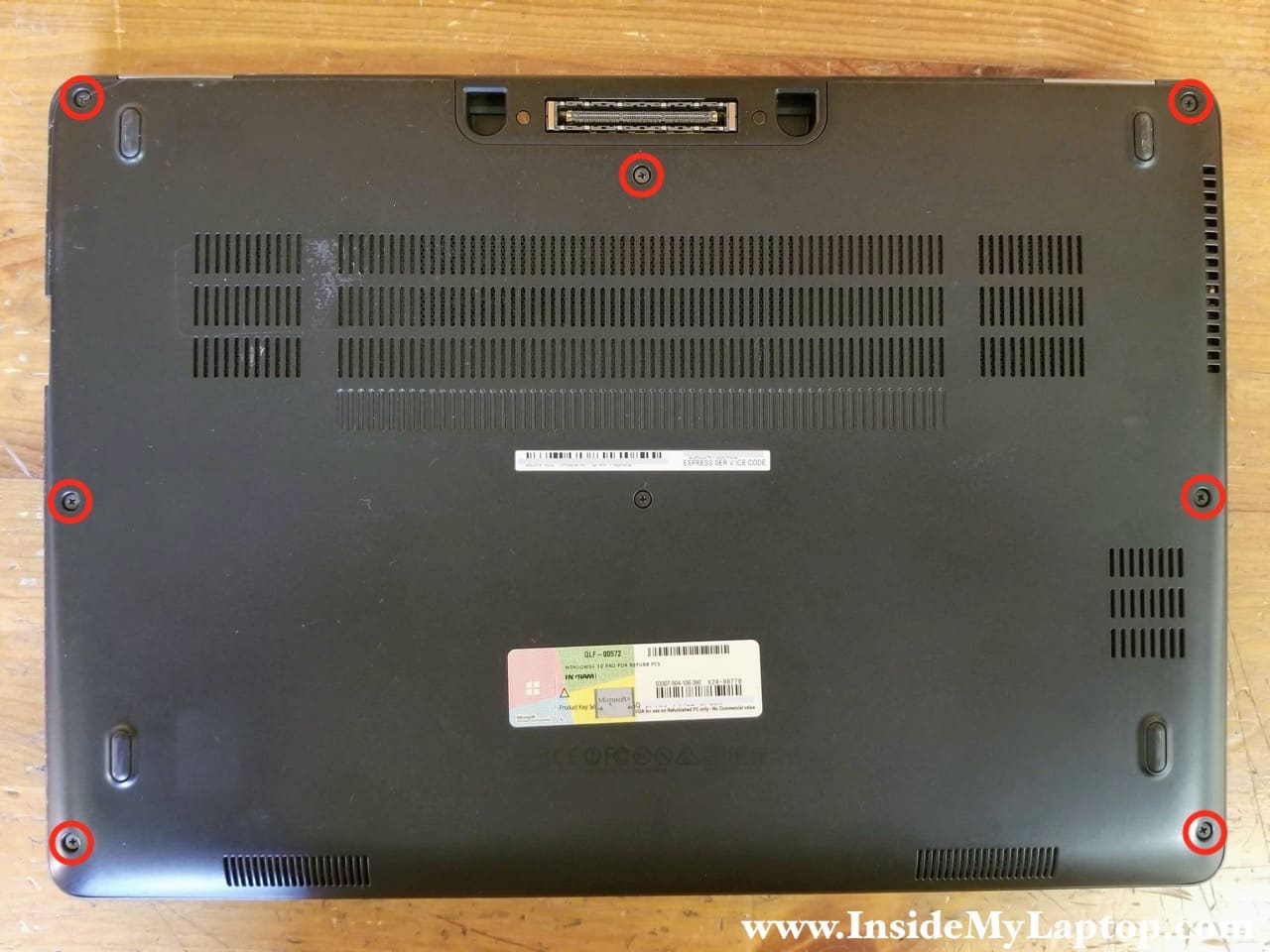
STPE 1.
Loosen seven captive screws on the bottom cover. These screws will stay attached to the cover when it’s removed.
STEP 2.
Pry up the bottom cover and remove it.
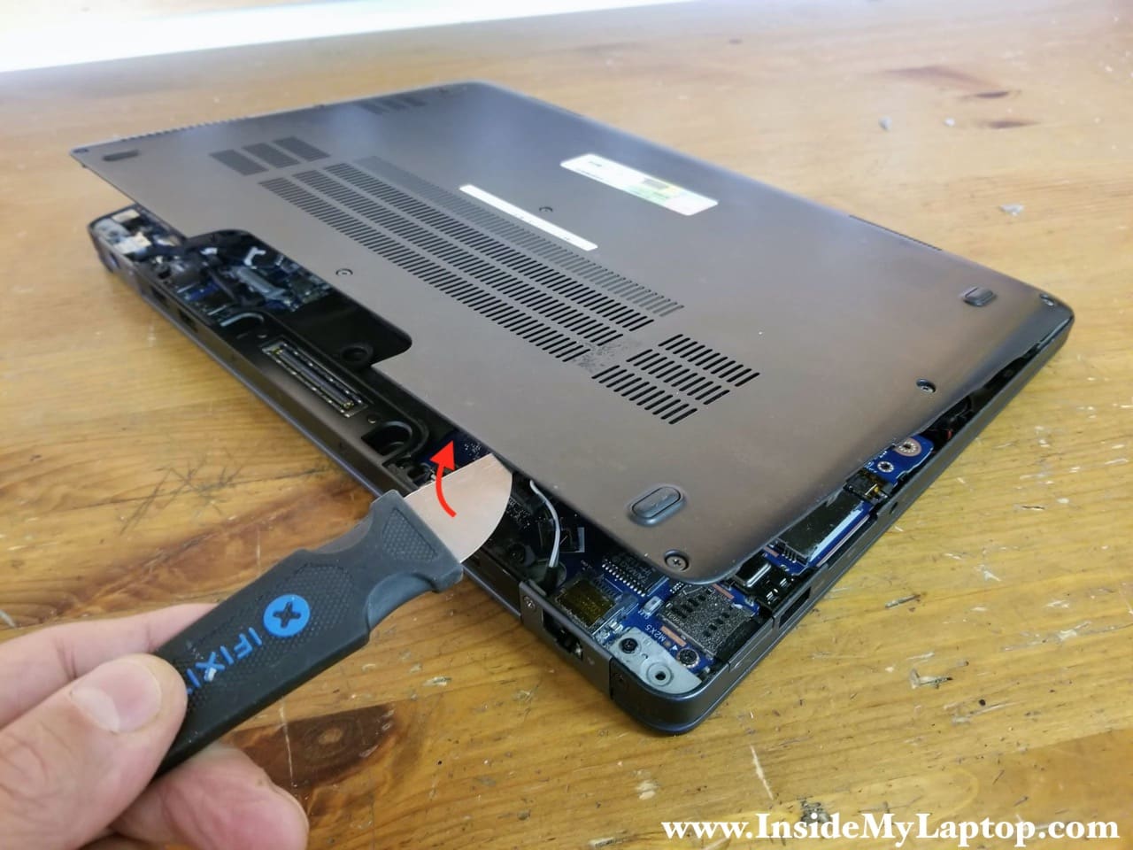
Both RAM modules can be easily accessed after the bottom cover is removed.
Dell Latitude E7470 maximum memory is 16GB (2x8GB modules) DDR4-2400 SODIMM.
STEP 3.
Remove three screws securing the battery and disconnect the battery cable from the motherboard.

STEP 4.
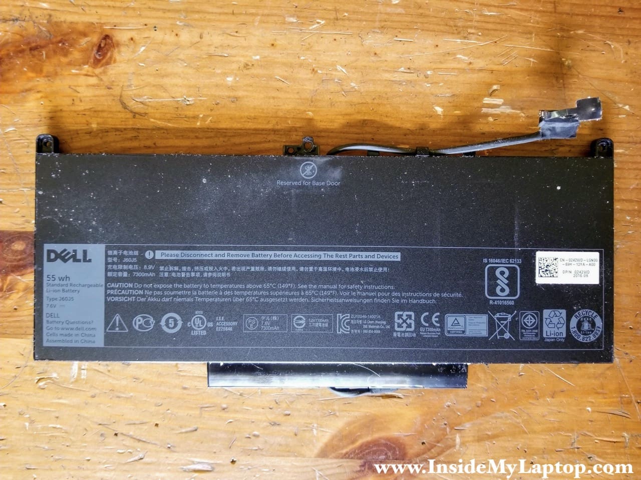
Lift up and remove the battery.
Dell Latitude E7470 battery type: J60J5.
Part number: 0242WD.
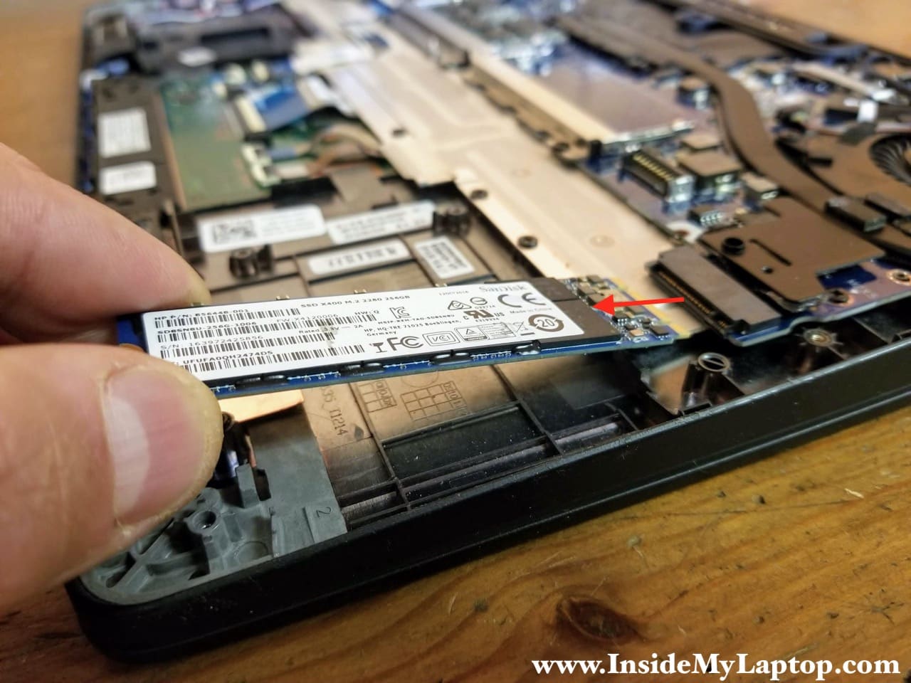
STEP 5.
Remove one screw securing the solid state drive and pull it out.
This particular Dell Latitude E7470 laptop was configured with a 256GB SanDisk M.2 2280 SATA SSD.
You can upgrade this drive to a larger size SSD, just make sure your new drive is M.2 SATA SSD Type 2280.
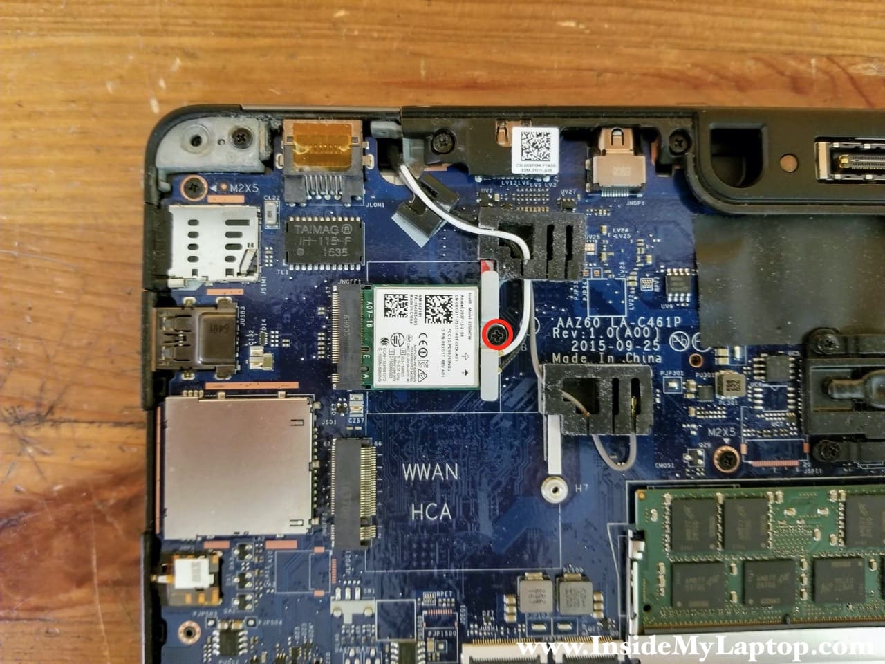
STEP 6.
Remove one screw securing the Wi-Fi card and antennas.
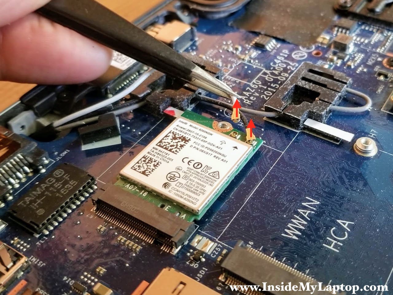
STEP 7.
Disconnect both antenna cables from the Wi-Fi card.
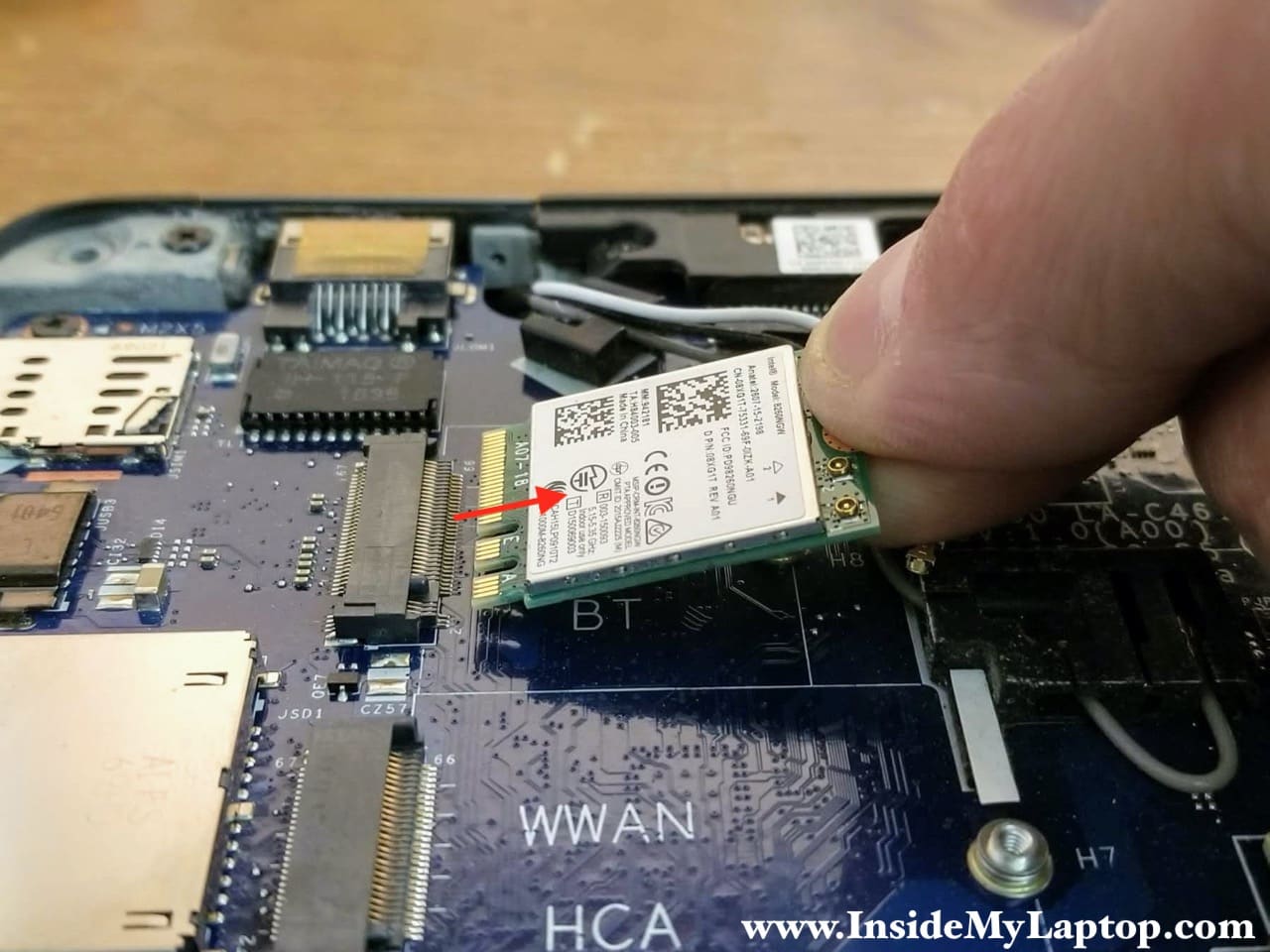
STEP 8.
Pull the Wi-Fi card out.
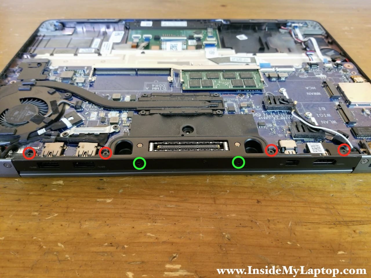
STEP 9.
Remove six screws securing the dock frame.
Two screws on the side (green) are different from four screws on the top (red). Keep them separated.
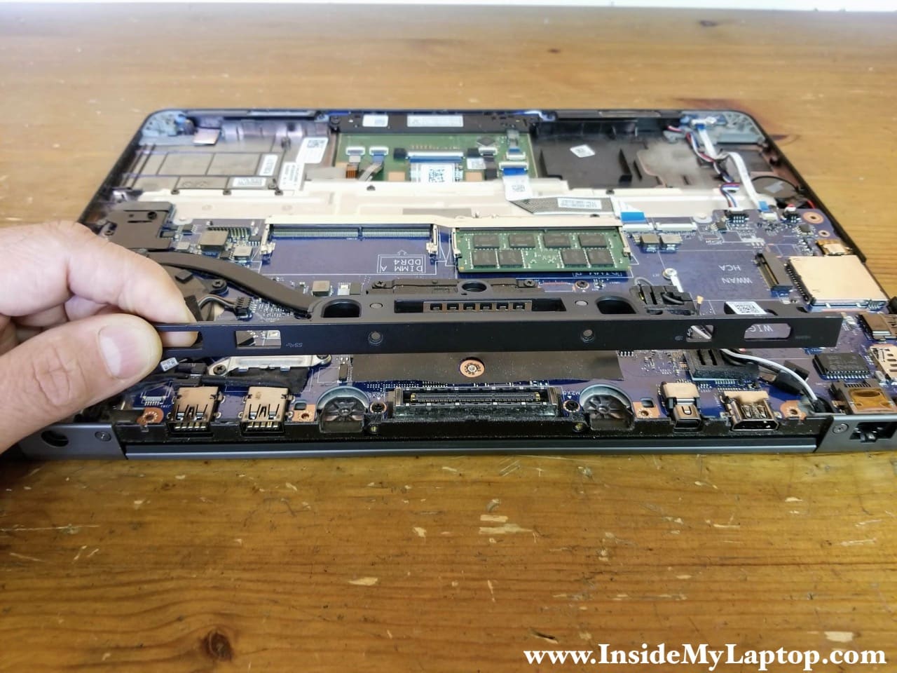
STEP 10.
Lift up and remove the dock frame.
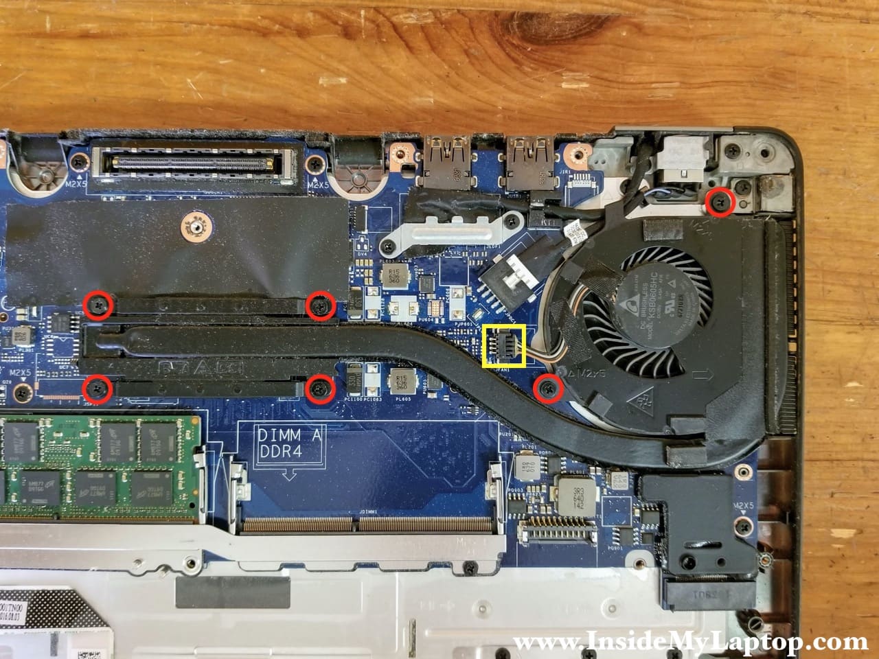
I’m not going to remove the heatsink assembly but it’s easy. Simply remove six screws, unplug the fan cable and carefully separate the heatsink assembly from the motherboard.
I will leave the heatsink attached to the motherboard.
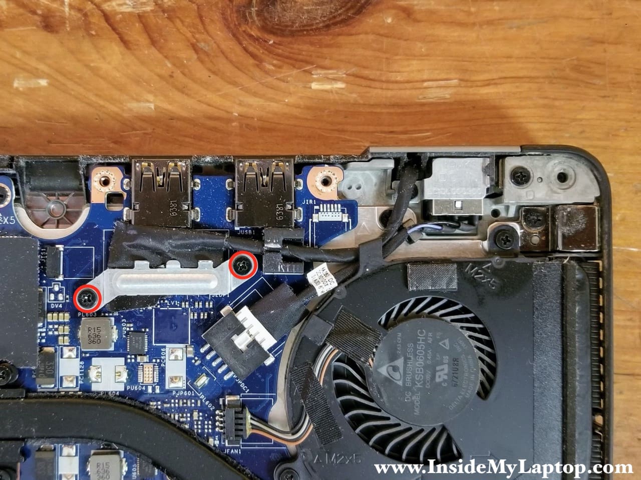
STEP 11.
Remove two screws securing the display cable bracket and remove it.
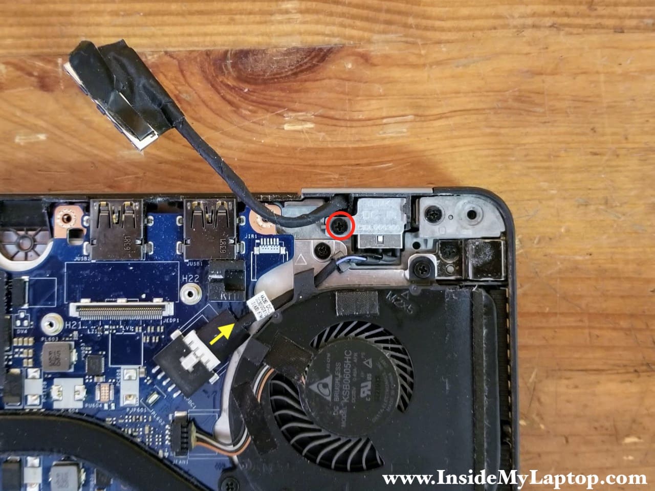
STEP 12.
Remove one screw securing the DC-IN power jack. Disconnect the DC jack cable from the motherboard.
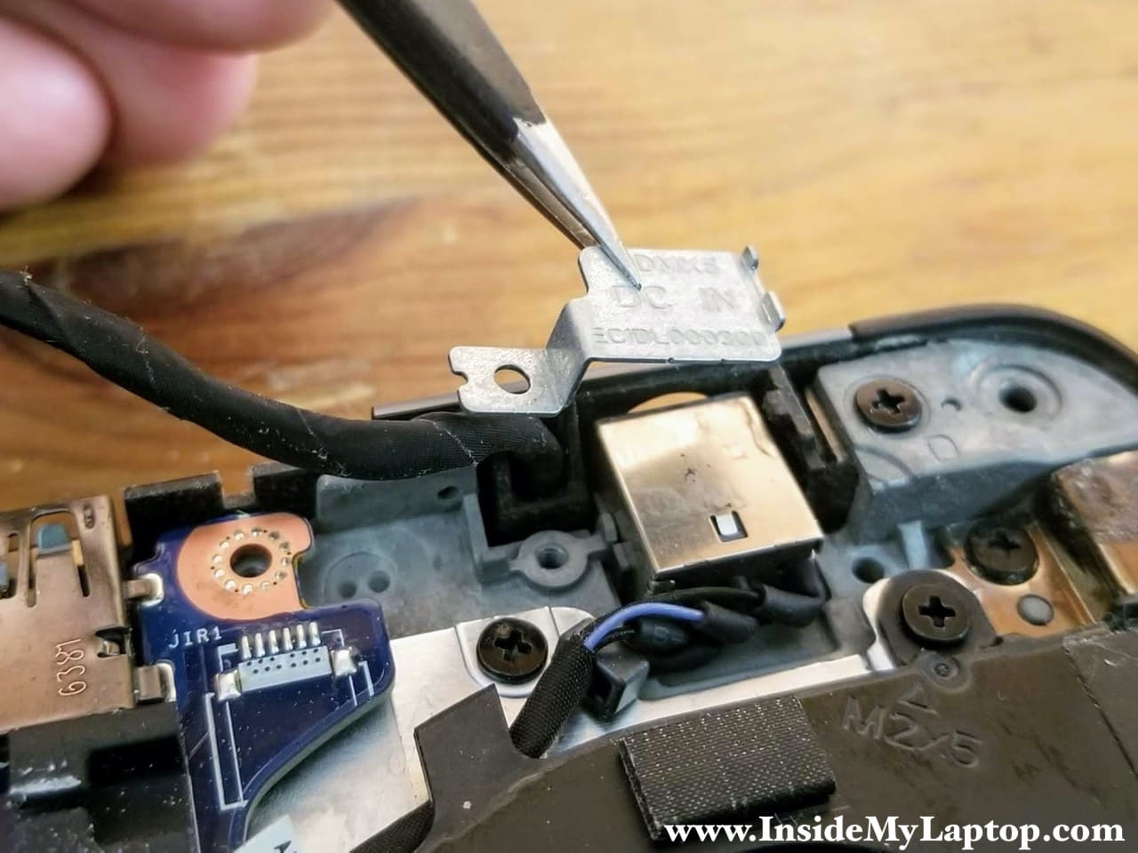
STEP 13.
Remove the DC-IN jack mounting bracket.
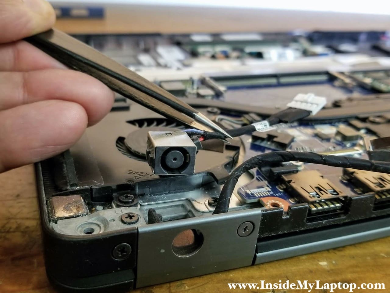
STEP 14.
Remove the DC jack.
STEP 15.
Remove nine screws securing the motherboard.
Two screws (blue) on the memory slots bracket are shorter than other seven screws (red).
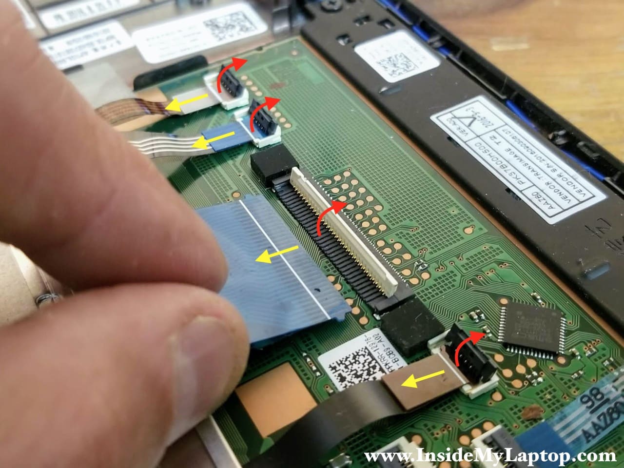
Disconnect the following color-coded cables:
– RTC battery cable (orange).
– Front LED board cable (yellow).
– Speaker cable (green).
– Touchpad cable (pink).

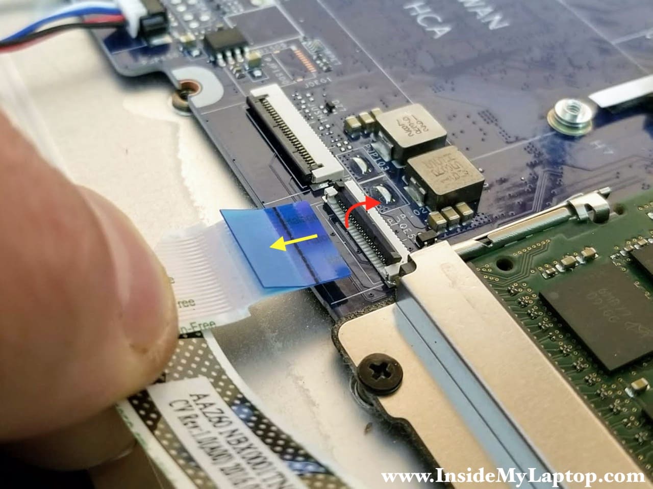
Here’s how to disconnect the touchpad and front LED board cables.
Lift up the locking tab to unlock the connector (red arrow) and pull the cable out (yellow arrow).
STEP 16.
Separate the metal bracket from the memory slots and remove it.
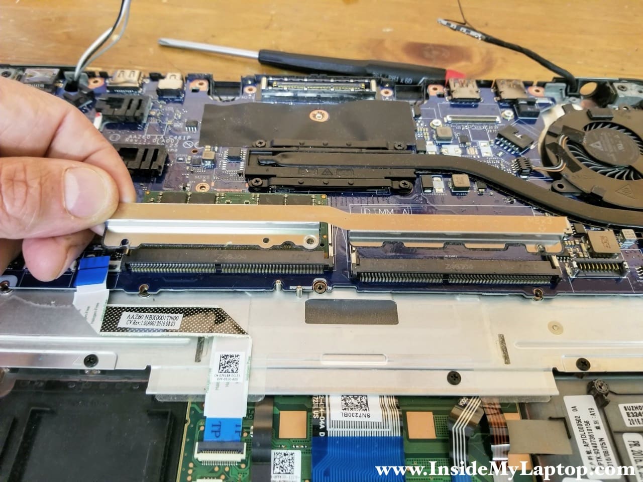
STEP 17.
Lift up one side of the motherboard and pull it towards the touchpad to separate from the top case assembly.
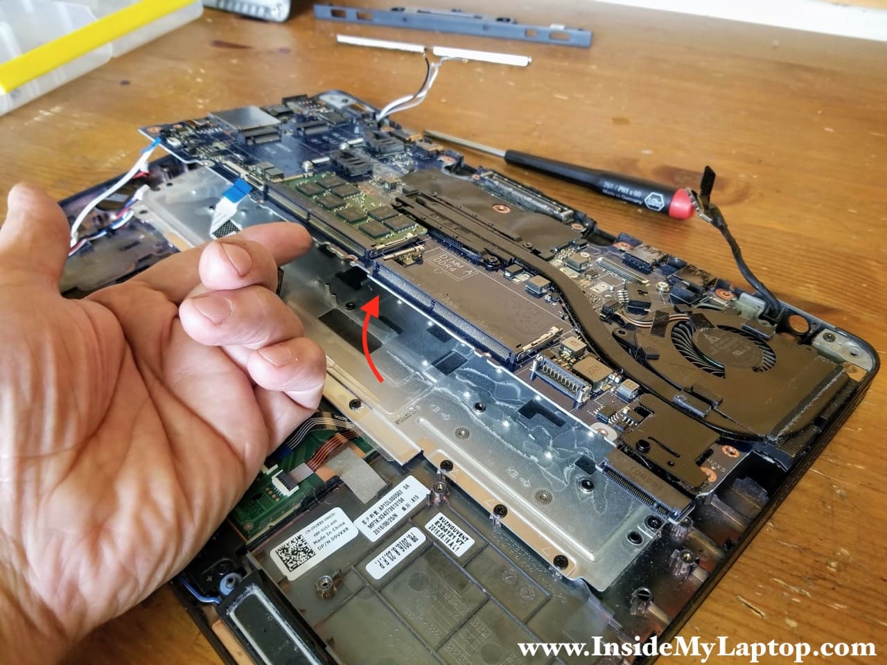
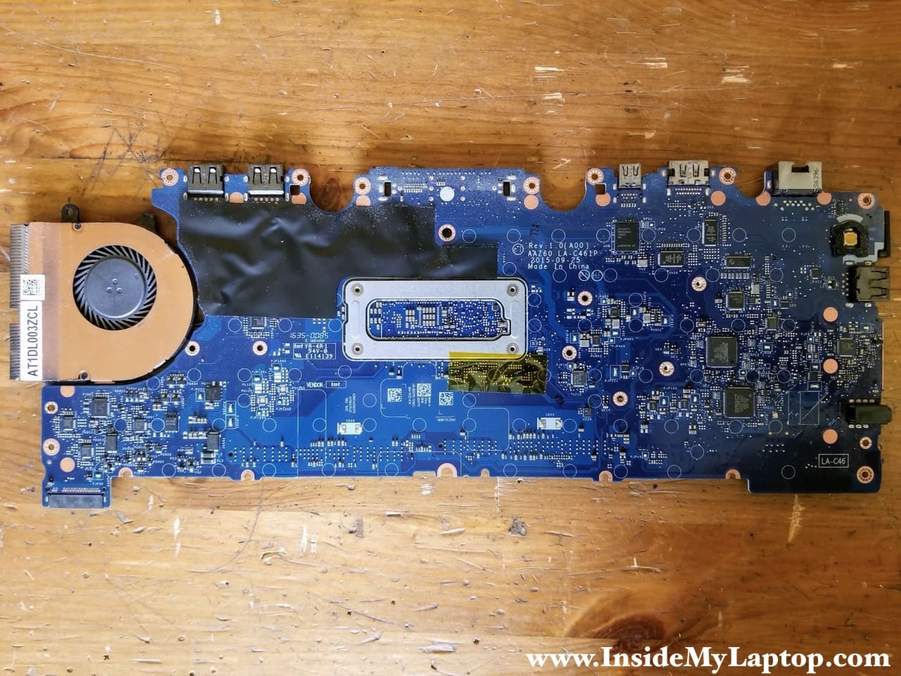
STEP 18.
Remove the motherboard.

Here’s the other side of the motherboard.
STEP 19.
Remove seventeen screws securing the keyboard bracket.
Disconnect all cables from the touchapad.
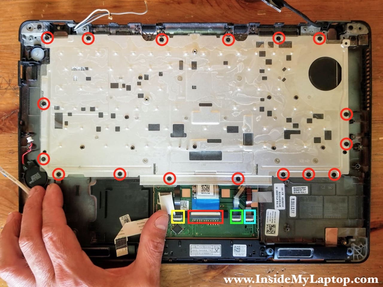
All cable connectors have to be unlocked before disconnecting the cable.
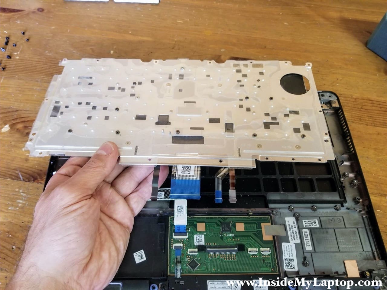
STEP 20.
Separate the keyboard assembly from the top case.
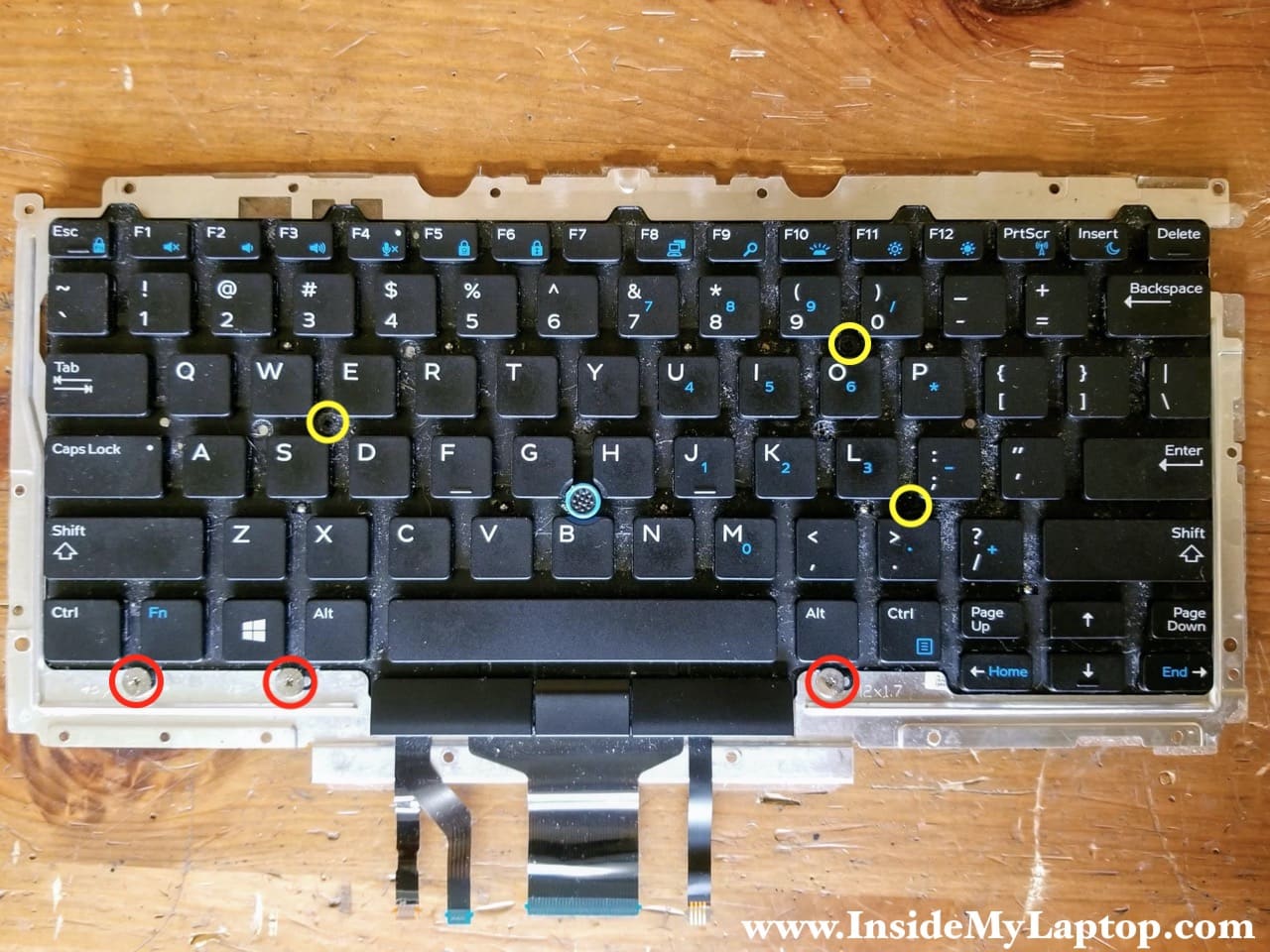
STEP 21.
Remove six more screws on the front side of the keyboard.
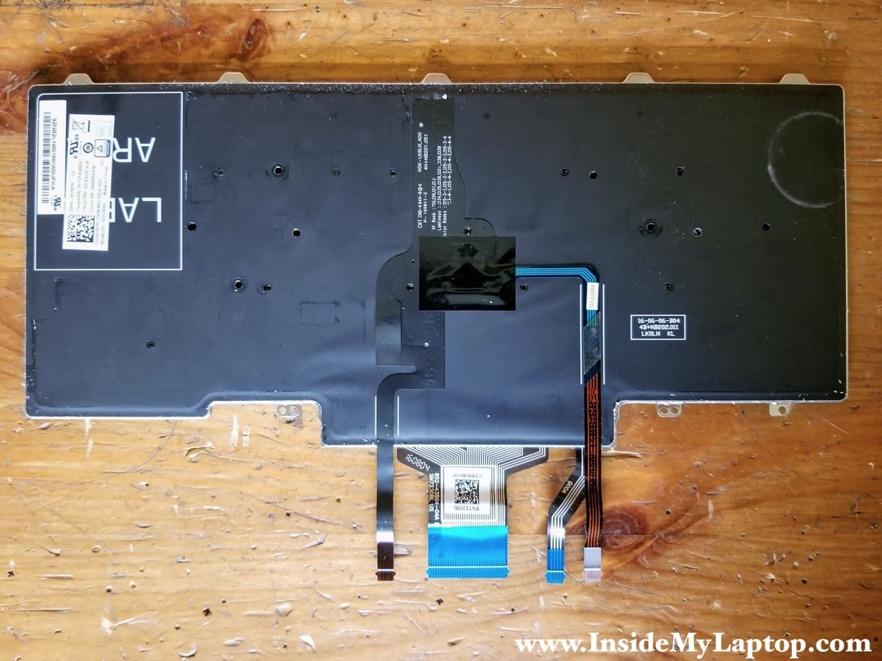
STEP 22.
Separate the keyboard from the metal mounting bracket.
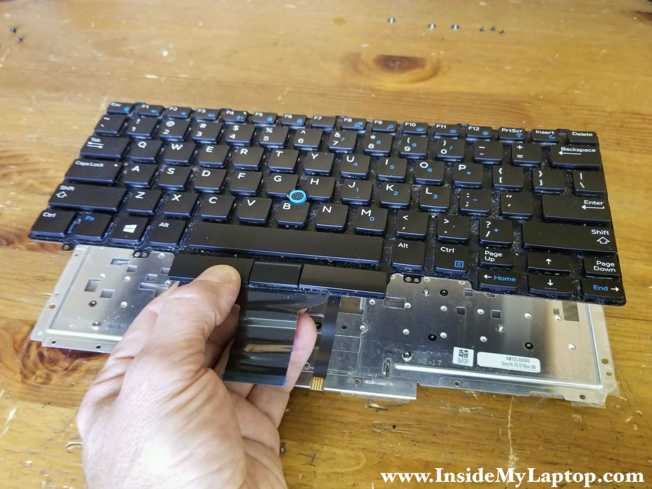
Now you can replace the keyboard with a new one if necessary.
Dell Latitude E7470 keyboard part number (US keyboard): 0D19TR.
Here’s Dell Latitude E7470 top case/display assembly with the keyboard removed.
The touchpad is glued to the top case.
