In this guide I explain how to disassemble an HP Notebook PC 17 model 17-x061nr.
You can use this guide for HP Notebook PC (Intel)
Models: HP 17-x000 – 17-x099
Models: HP 17-x100 – 17-x199
Steps 1-23: how to disassemble the base assembly.
Steps 23-27: how to remove the LCD screen.
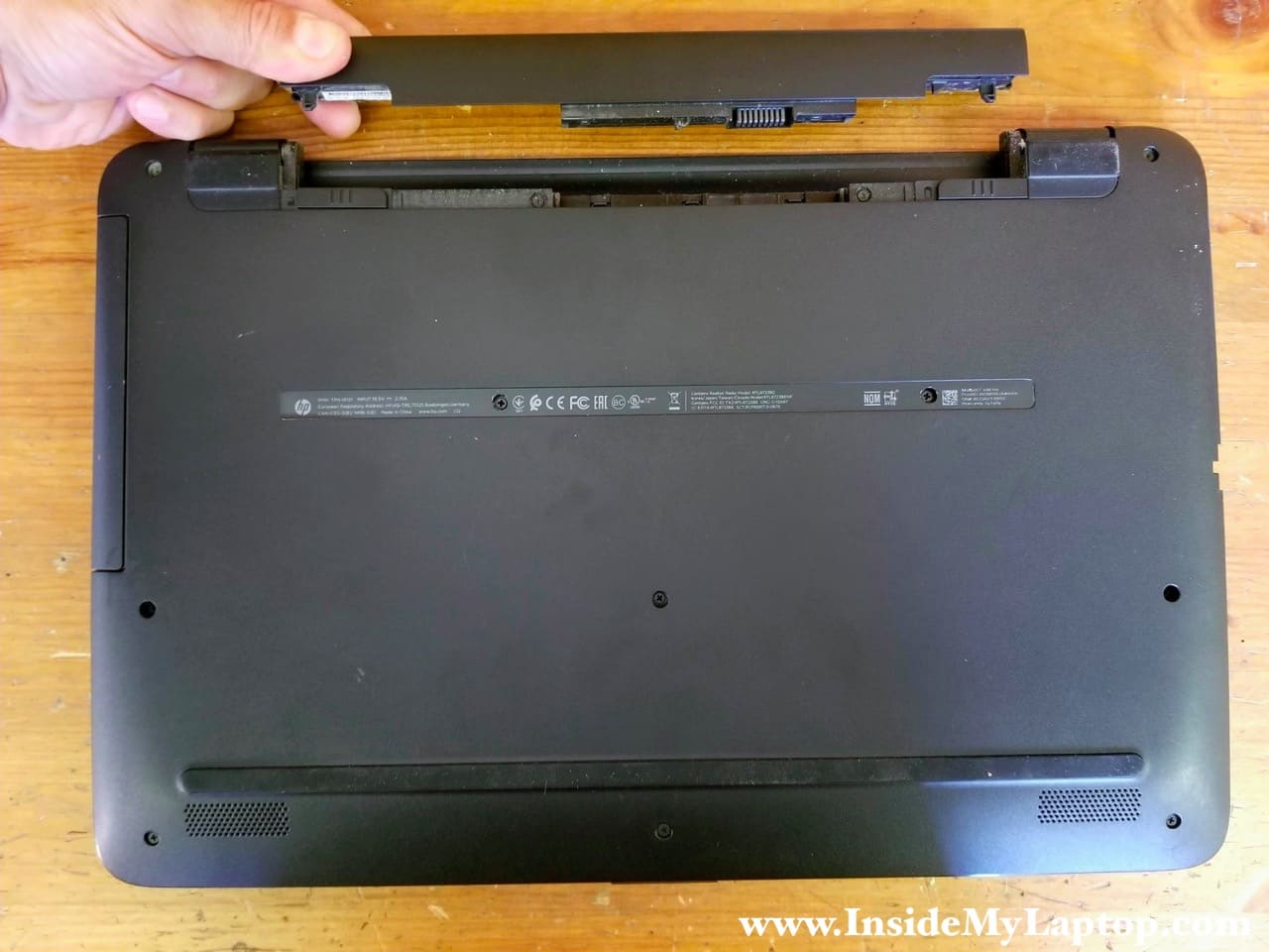
STEP 1.
Unlock and remove and replace the battery if necessary.
STEP 2.
Remove all screws from the bottom cover.
Pull the optical DVD drive out and remove it.
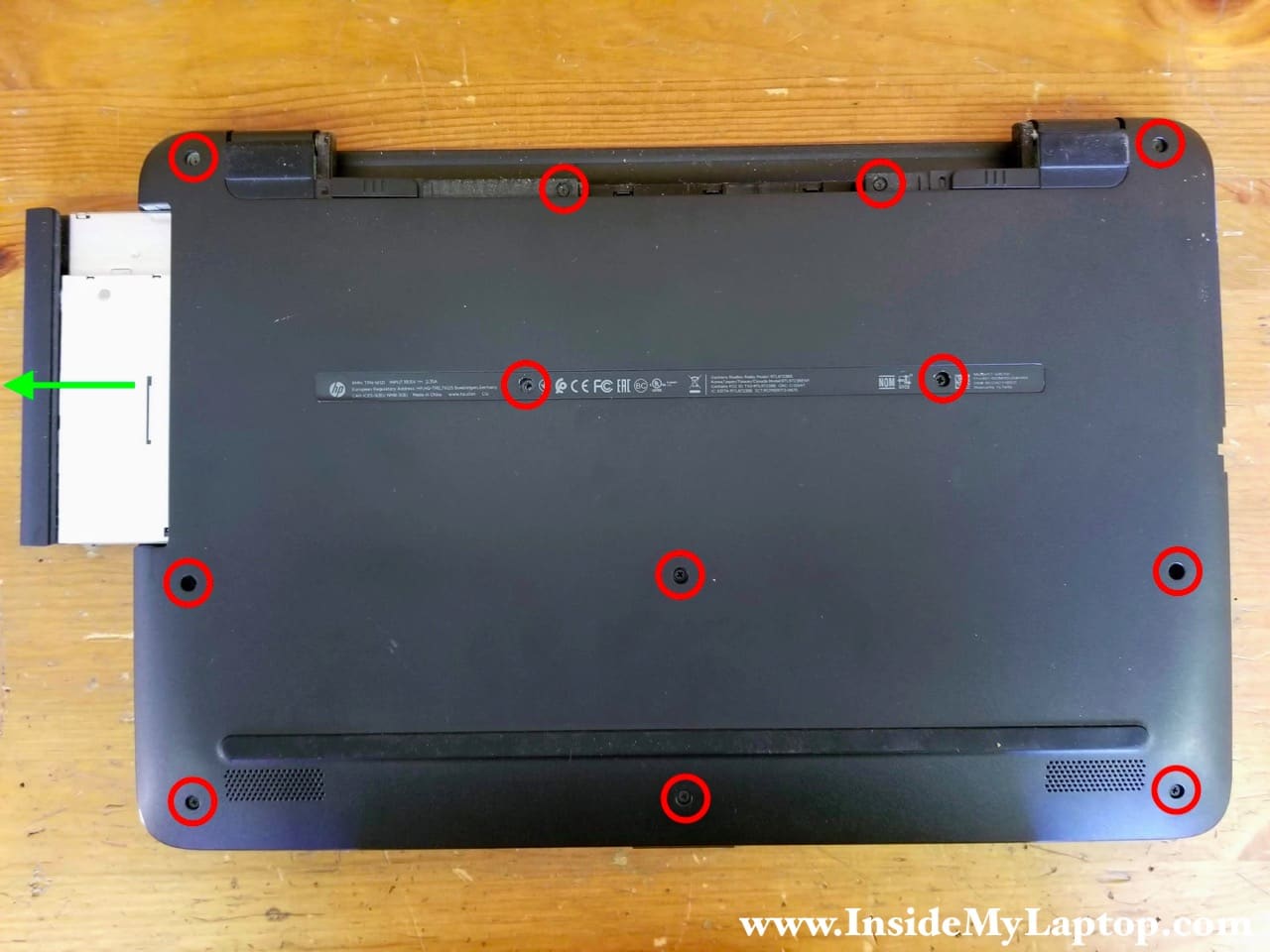
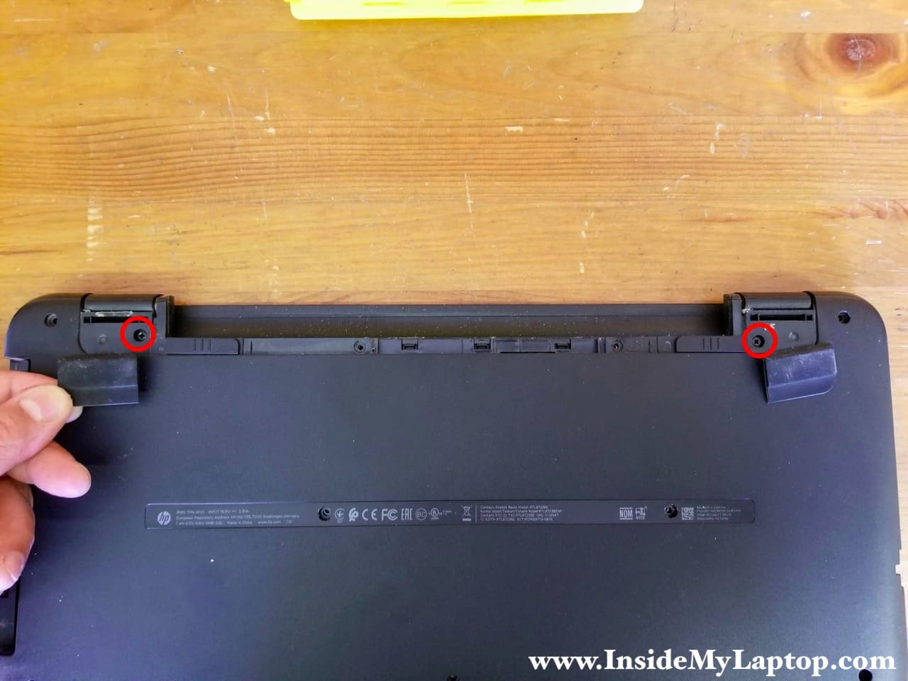
There are two hidden screws securing the bottom cover. These screws are located under the bottom feet.
Remove both bottom feet and remove hidden screws.
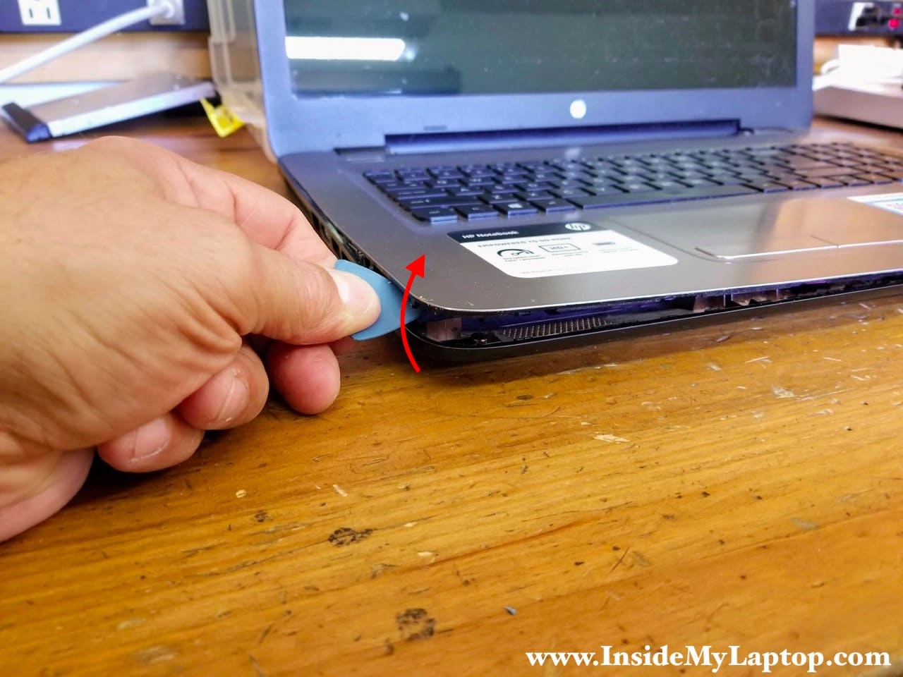
STEP 3.
Start separating the keyboard/palmrest assembly from the bottom cover. I’m using a plastic case opener tool for that.
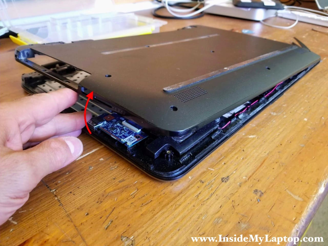
STEP 4.
Turn the laptop upside down and continue separating the bottom cover.
HP Notebook PC 17-x061nr has all internal components mounted to the keyboard/palmrest assembly.
I found it’s easier to remove the bottom cover if you start doing it from the side with the DVD drive opening.
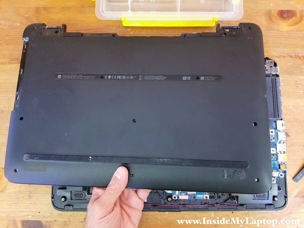
STEP 5.
Remove the bottom cover.
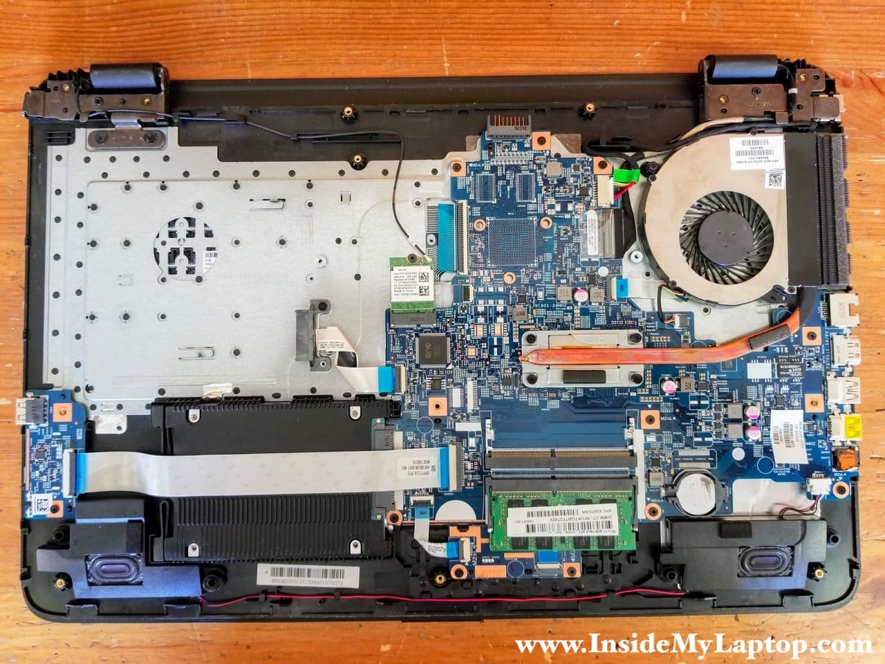
The hard drive mounted under the USB/SD card reader cable. Let’s remove the USB/SD card board first.
STEP 6.
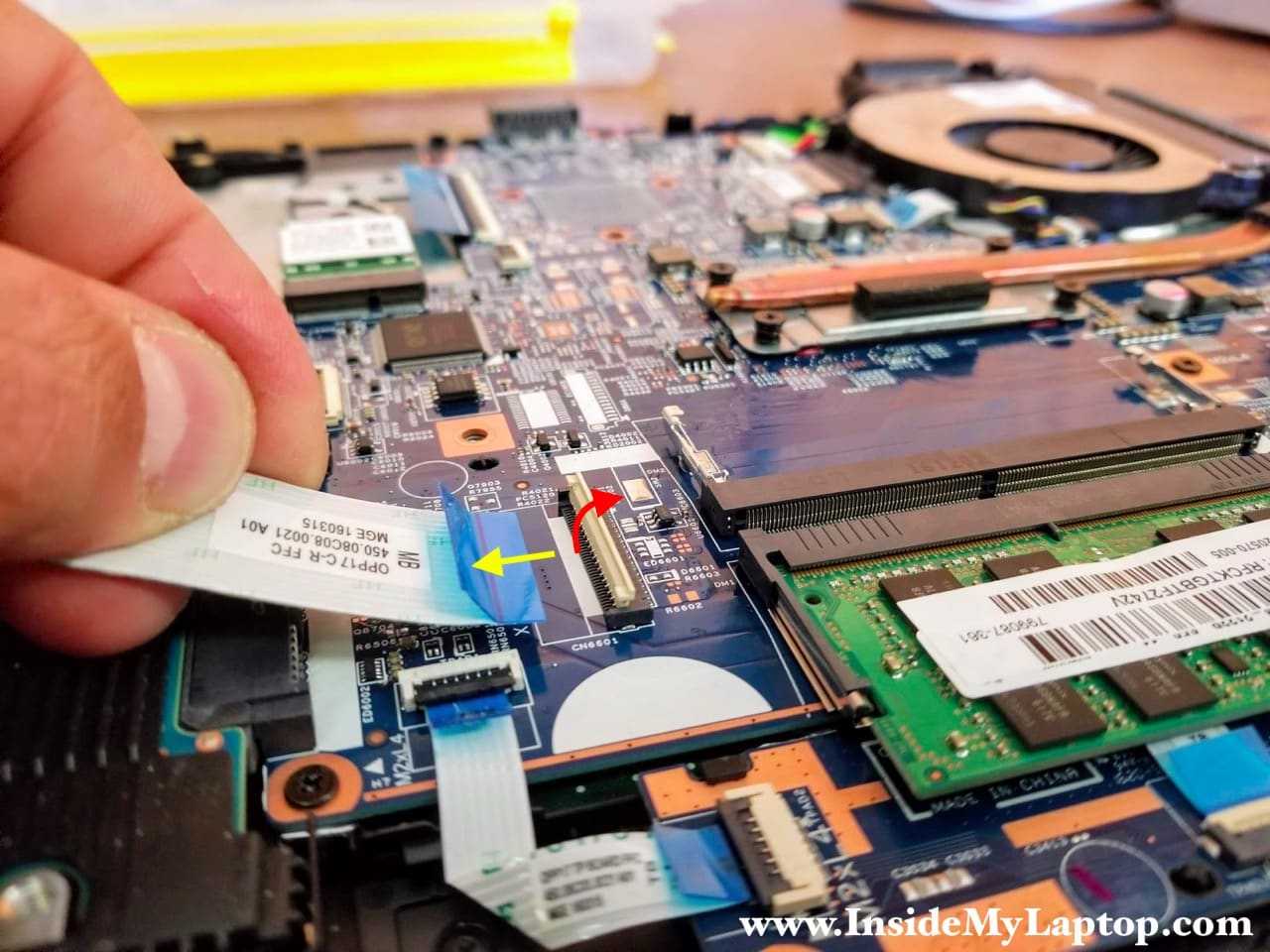
Disconnect the USB/SD card reader cable from the motherboard.
Unlock the connector first by lifting up the locking tab (red arrow). After the connector is unlocked, pull the cable out.
STEP 7.
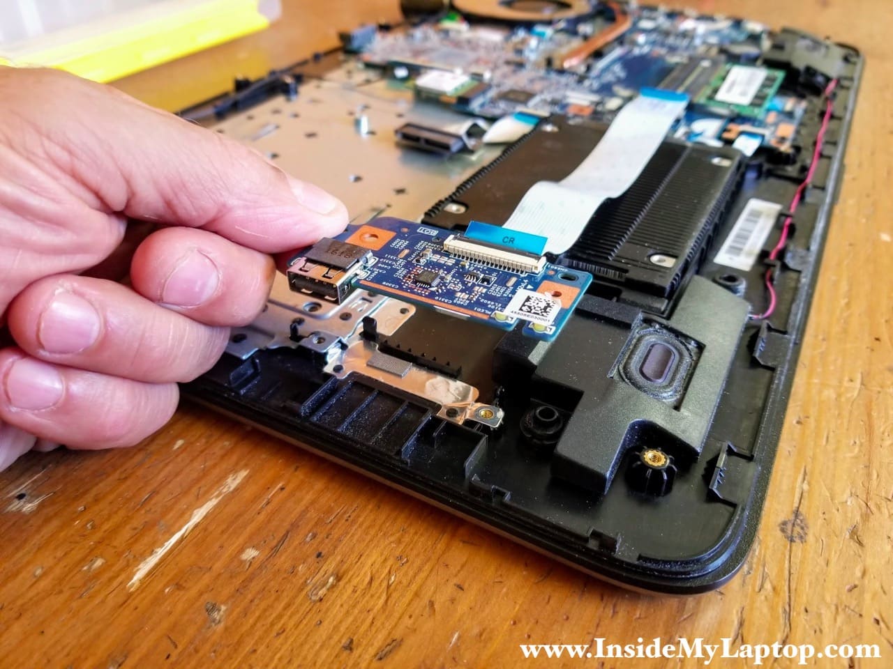
Remove one screw securing the USB/SD card reader board.
Lift up and remove the board with the cable.
STEP 8.
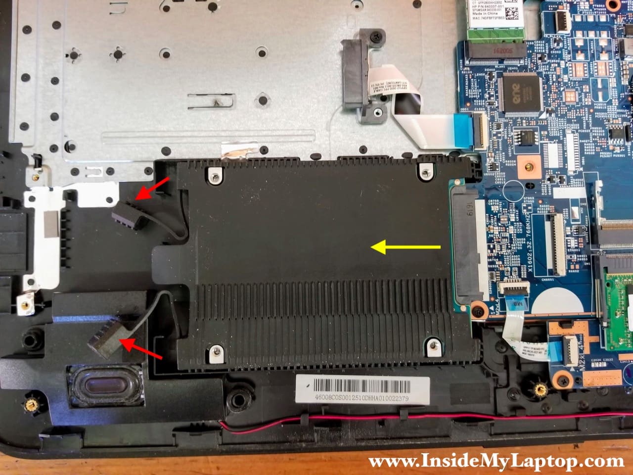
Remove two rubber pads securing the hard drive.
Slide the hard drive to the shown direction (yellow arrow) to disconnect it from the SATA port.
STEP 9.
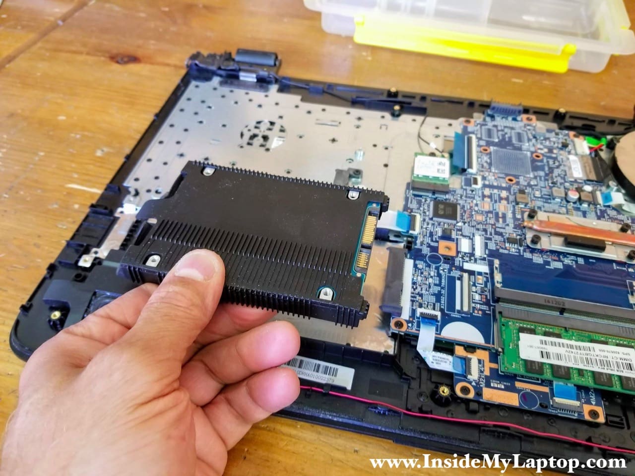
Remove the hard drive. Upgrading this hard drive to a 2.5″ SATA solid state drive will improve laptop performance.
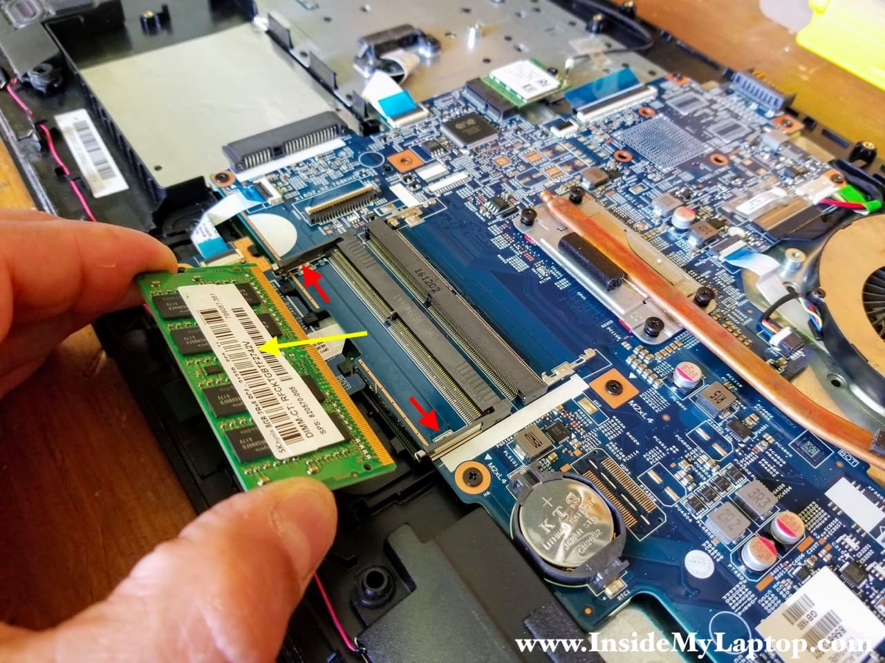
STEP 10.
HP Notebook PC 17-x061nr motherboard has two RAM slots. In my case I had only one RAM module installed.
This model will support up to 16GB (2x8GB) DDR4 2400/2666/3200 SODIMM RAM modules.
Remove the memory module. Spread latches on the RAM slot (red arrows) until the module pops up at a 30-degree angle. Pull the memory module out.
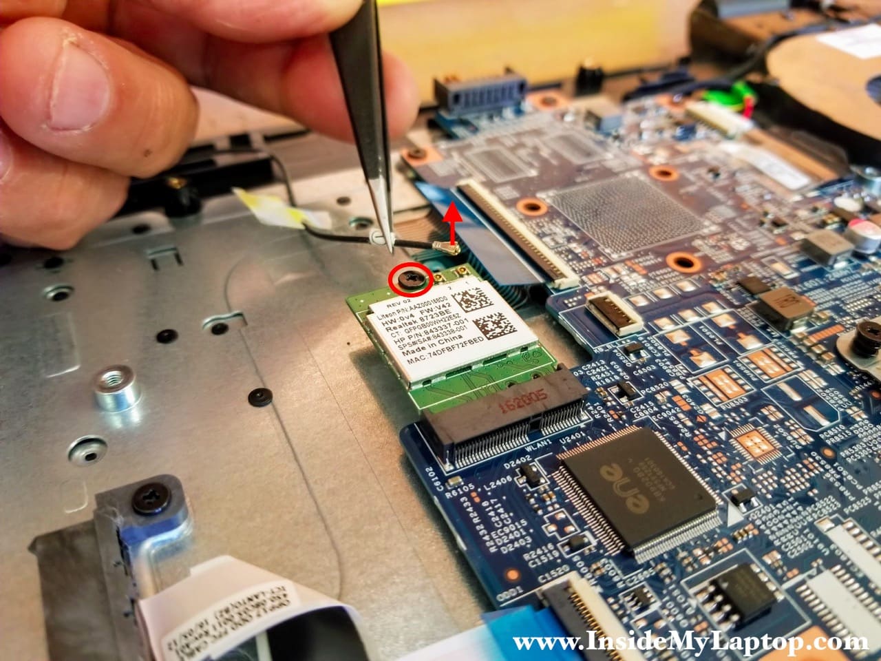
STEP 11.
Disconnect one antenna cable from the wireless card.
Remove one screw securing the wireless card.
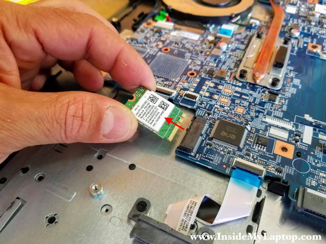
STEP 12.
Pull the wireless card out.
STEP 13.
Remove all screws securing the motherboard.
Disconnect the following color-coded cables:
– Keyboard cable (orange).
– Optical DVD drive connector board cable (yellow).
– Touchpad button board cable (green).
– Speaker cable (light blue).
– Power button board cable (dark blue).
– DC power jack cable (pink).

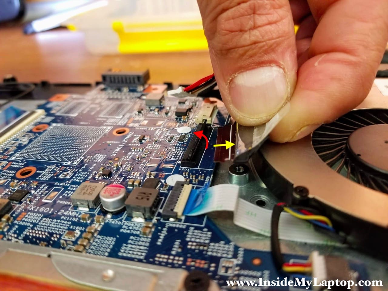
STEP 14.
Disconnect the display video cable.
Unlock the connector first by lifting up the locking tab (red arrow). Pull the display video cable out (yellow arrow).
STEP 15.
Separate the motherboard from the keyboard/palmrest assembly and remove it completely.
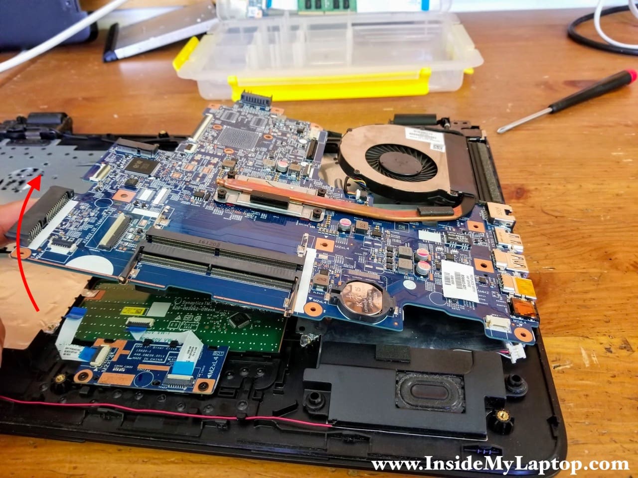
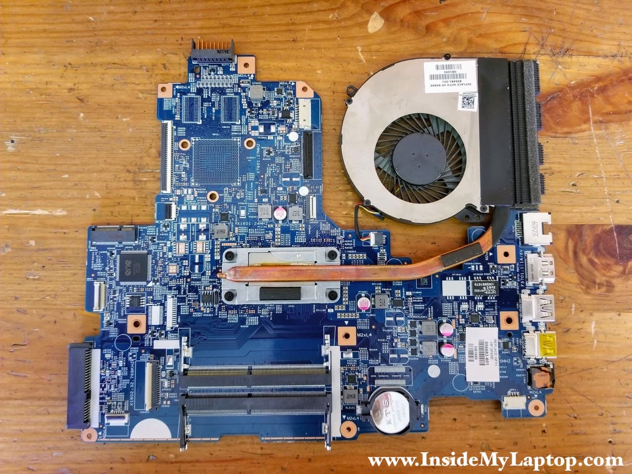
The cooling fan attached to the heatsink.
You can find a new replacement fan using HP spare part number: 856681-001.
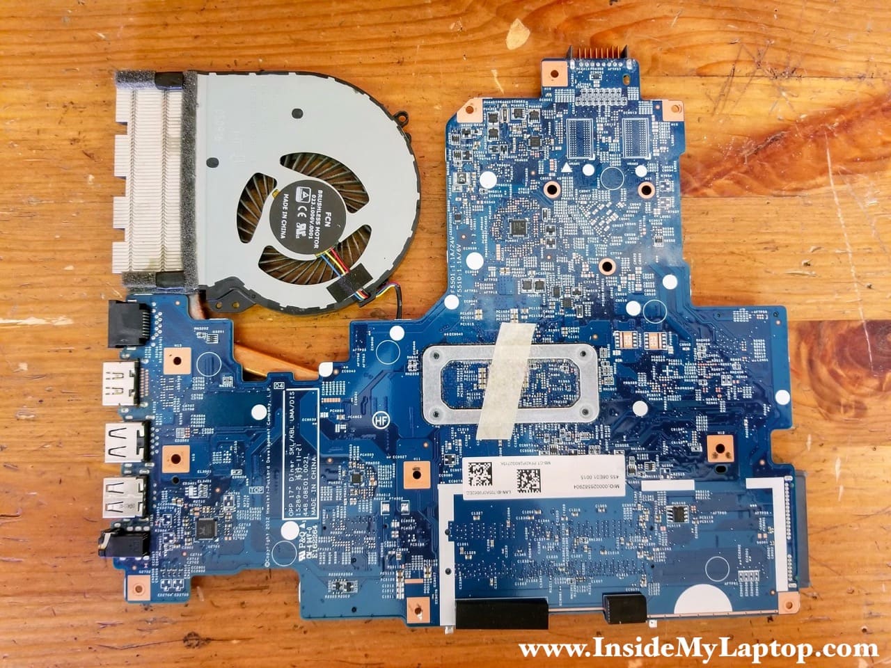
Here’s the other side of the motherboard.
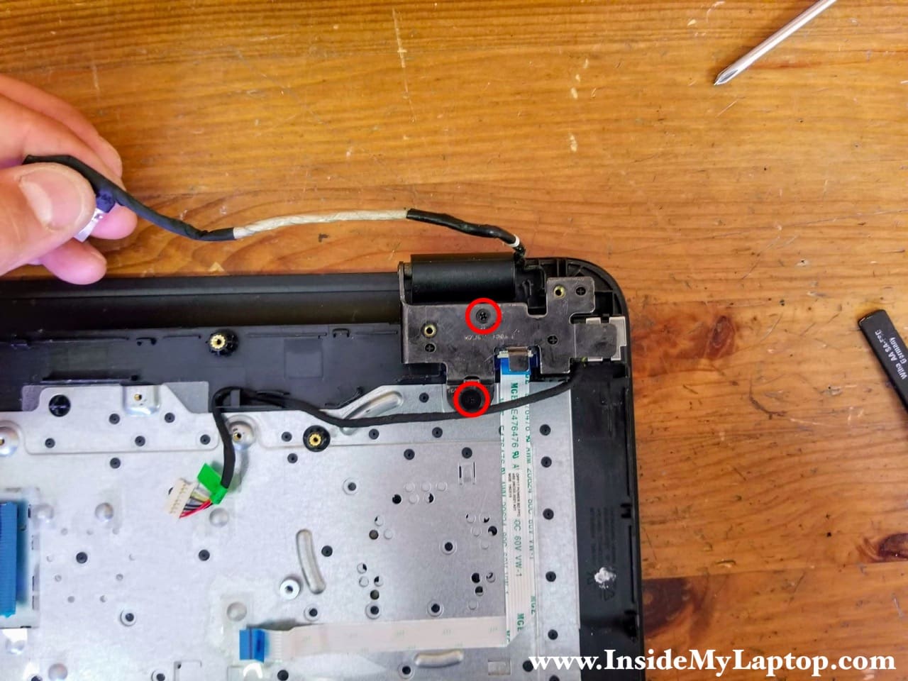
STEP 16.
In HP Notebook PC 17-x061nr the DC power jack and power button board mounted under the left display hinge.
Yes, it’s necessary to remove the motherboard in order to access and remove these boards.
Remove two screw securing the left display hinge.
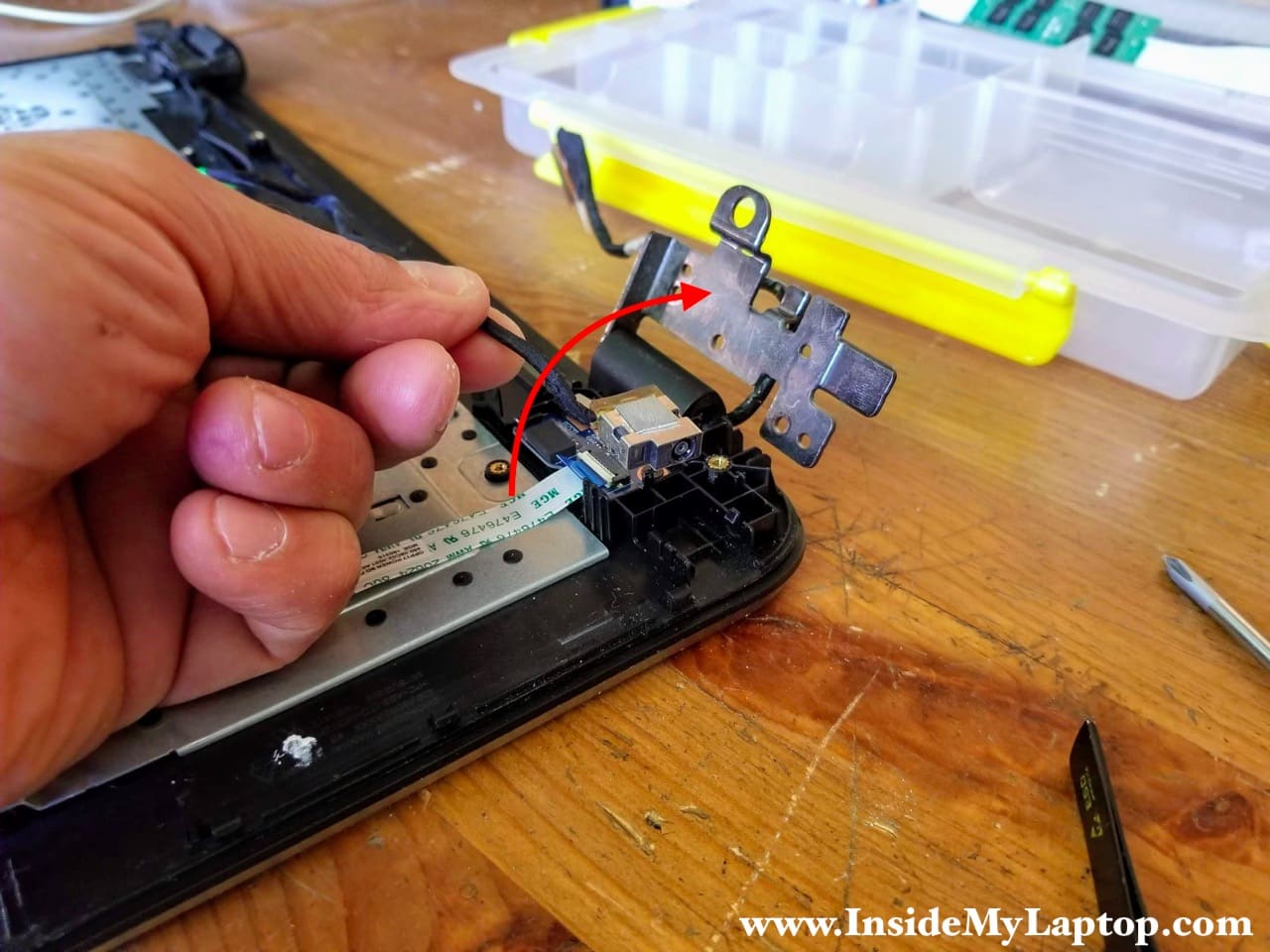
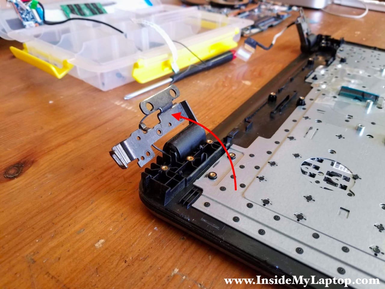
STEP 17.
Open up the left display hinge as it shown on the following picture.
Lift up and remove the DC jack harness.
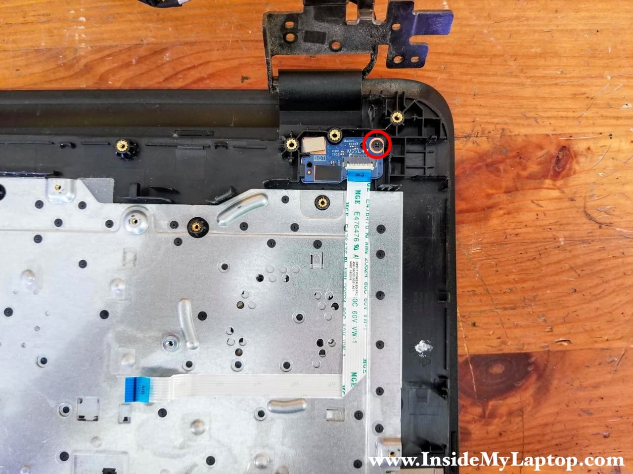
STEP 18.
Remove one screw securing the power button board.
The flat cable glued to the top case. Peel off the cable.
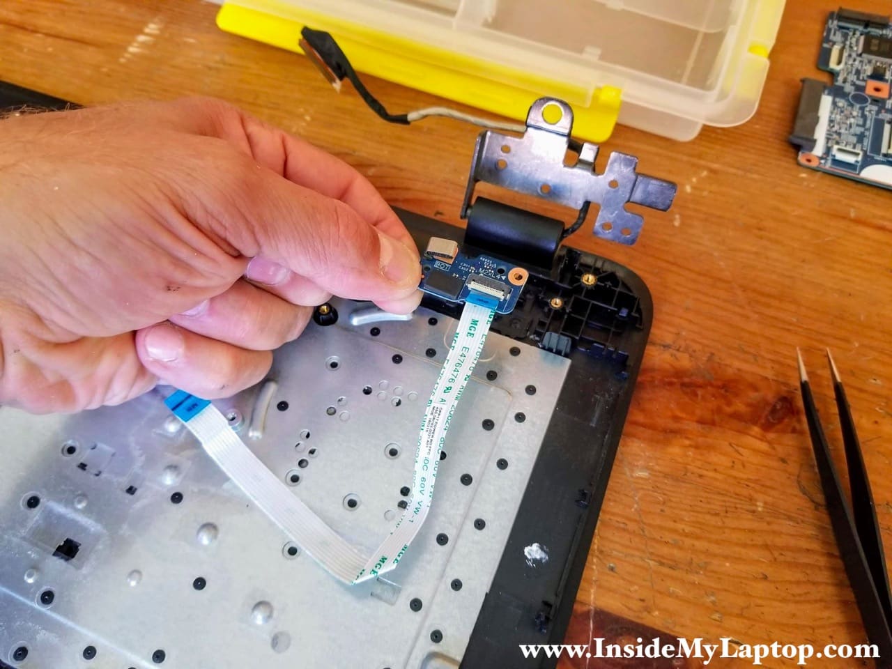
STEP 19.
Remove the power button board with the cable attached to it.
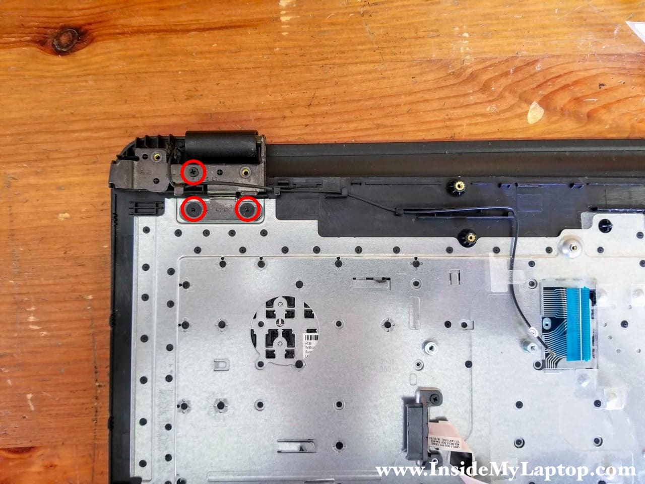
STEP 20.
Remove three screws securing the right display hinge.
Unroute the wireless card antenna cable from the guided path on the top case.
STEP 21.
Open up the right display hinge.
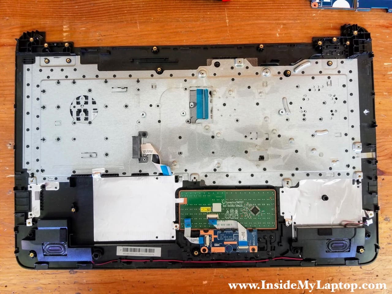
STEP 22.
Separate the keyboard/palmrest assembly from the display panel.
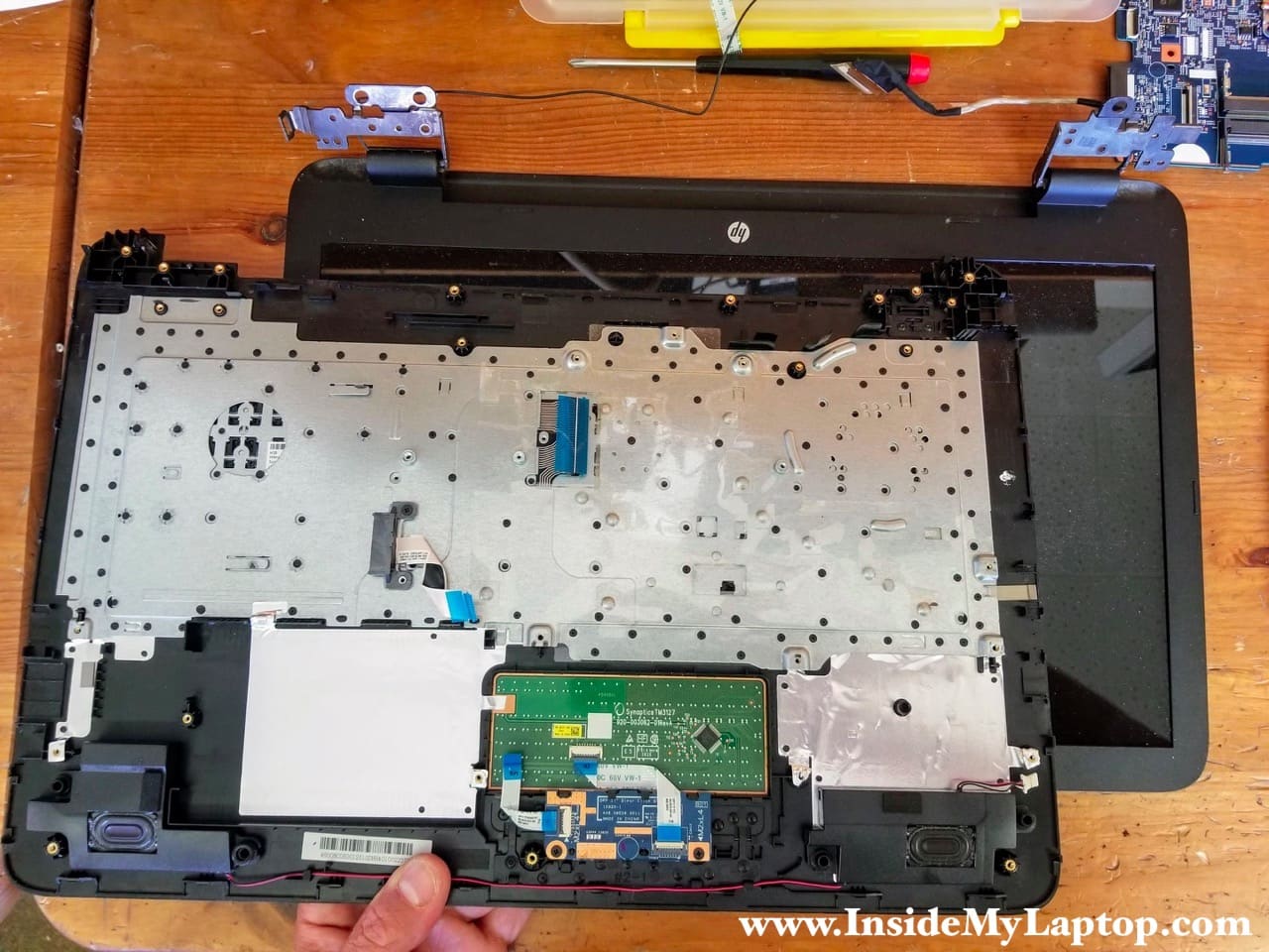
The display panel can be taken apart while it’s still attached to the laptop base. I will show how to remove the LCD screen in the following steps.
HP Notebook PC 17 has the keyboard permanently attached to the top case. It cannot be easily removed and replaced. Check out this keyboard removal trick. The trackpad is glued to the top case.
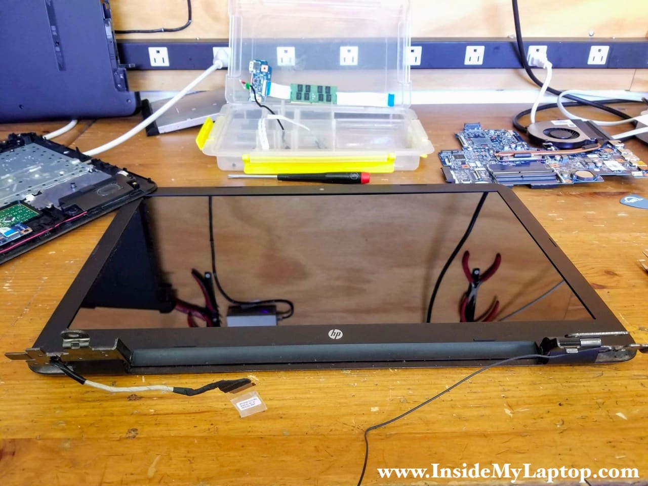
HP Notebook PC 17 screen removal
As I mentioned earlier, the LCD screen can be removed while the display panel is still attached to the base (as shown in my example).
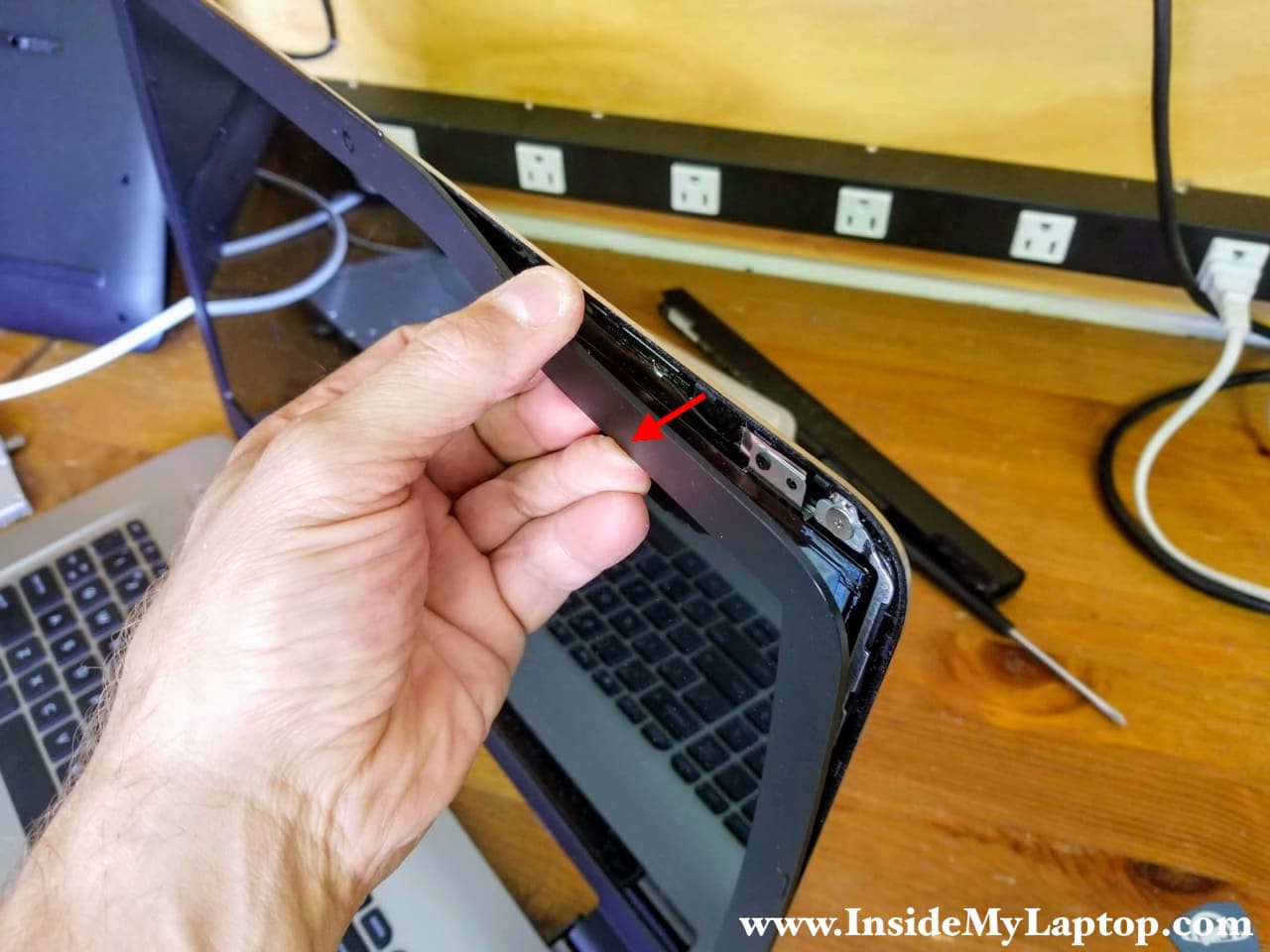
STEP 23.
Insert your fingers between the display bezel and LCD screen. Start separating the bezel from the display. Wiggle the bezel to disengage hidden latches.
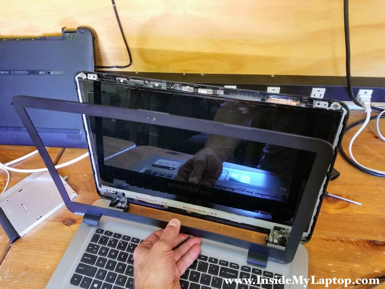
STEP 24.
Remove the display bezel completely.
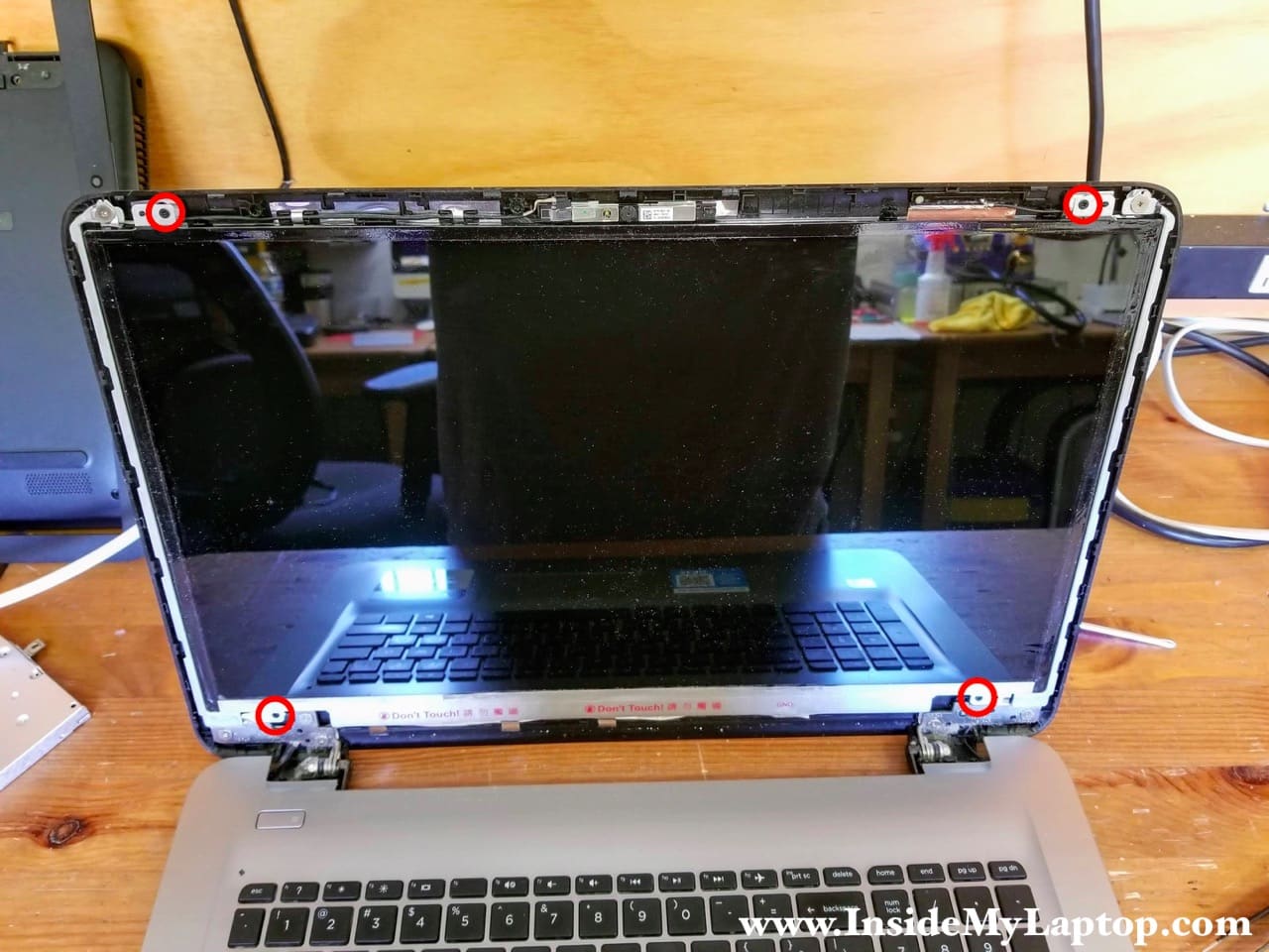
STEP 25.
Remove four screws securing the LCD screen to the display back cover.
STEP 26.
Separate the LCD screen from the back cover and placed it on the keyboard.
Now you can access the display video cable on the back.
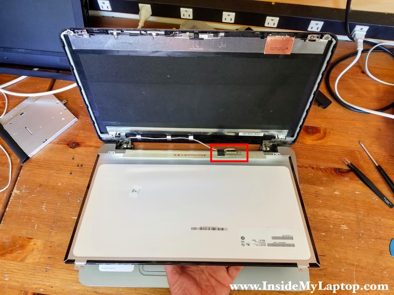
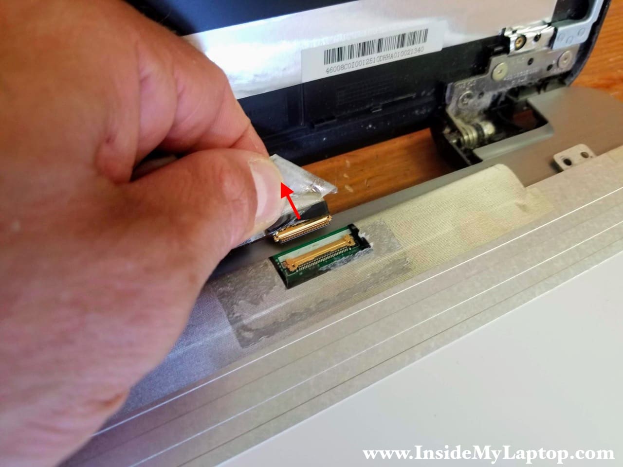
STEP 27.
Peel off clear tape securing the connection.
Unplug the display video cable from the LCD screen.
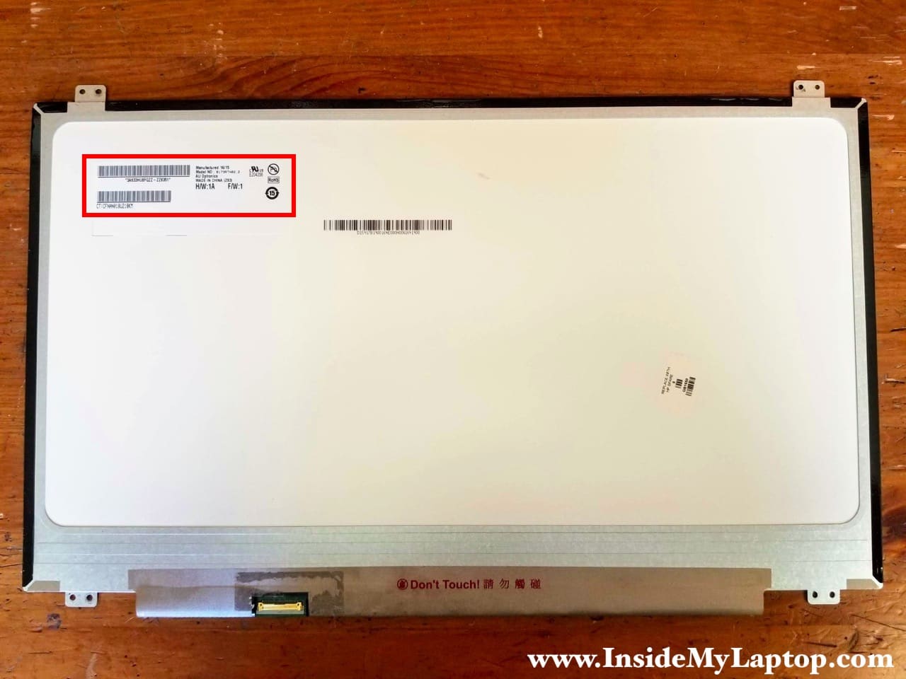
If you need to replace the LCD screen, you can find a new one using the model number printed on the back.
This HP Notebook PC 17-x061nr had the following screen installed: B173RTN02 .2 manufactured by AU Optronics.
Related post: Full disassembly of an HP Notebook PC 17-x116dx.
Keith
Thanks
Kannan Aiyar
Hi Keith, really well laid-out instructions. I have been looking for something like this for a long time. It seems the Notebook model is not very popular, so there are very few instructions online for it.
I want to replace my keyboard. Is there a way to remove/replace the keyboard without taking out everything else?