In this guide I show how to take apart a Dell XPS 17 L702X.
I will remove the bottom cover in order to access the main internal components.
Before you start, make sure it’s turned off and battery removed.
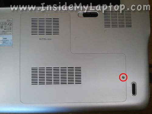
STEP 1.
Remove the service cover located on the bottom. It’s secured by one screw.
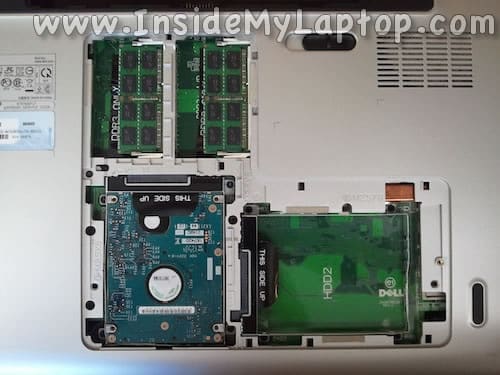
STEP 2.
Under the service cover you can access the hard drive and both RAM modules.
This laptop supports up to 16GB DDR3-12800 SODIMM RAM modules.
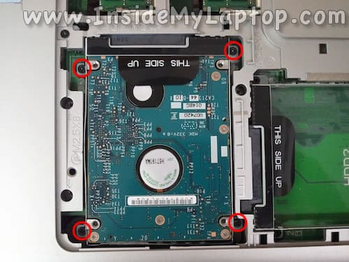
STEP 3.
Remove four screws securing the primary hard drive caddy.
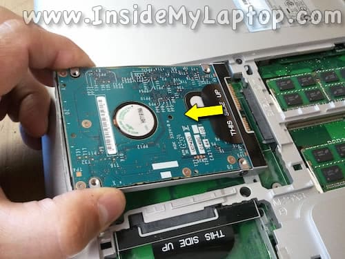
STEP 4.
Lift up the back side of the drive and disconnect it from the motherboard.
Remove the hard drive from the laptop.
I recommend replacing this regular 2.5″ SATA hard drive to a 2.5″ SATA solid state drive. Doing so will improve the laptop performance significantly.
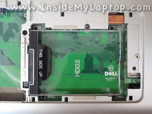
STEP 5.
In my model I didn’t have the second hard drive installed.
If you do, remove it the same way as the first one.
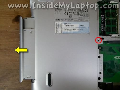
STEP 6.
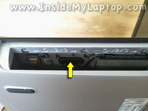
Remove one screw securing the optical drive.
Pull the optical drive to the left and remove it from the case.
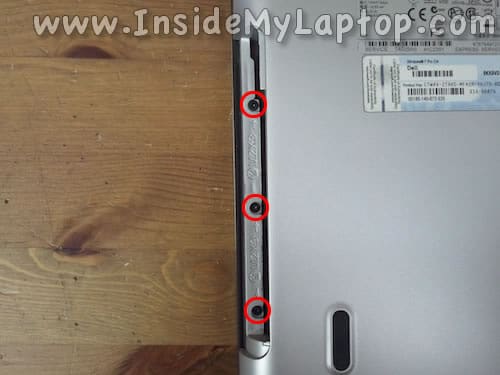
STEP 7.
Remove three screws securing the palm rest assembly.
STEP 8.
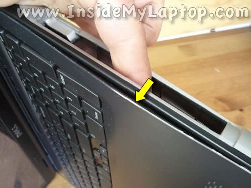
In the optical drive bay you will find an opening where you can push on the back side of the palm rest.
STEP 9.
When you push on the back side, the palm rest will separate from the bottom cover a little bit.
STEP 10.
Continue separating the palm rest from the bottom with your fingers.
Also, you can use a guitar pick (or any other piece of plastic) as a case opener.

STEP 11.
Lift up the palm rest assembly.
Be careful, there are two cables connecting it to the motherboard.
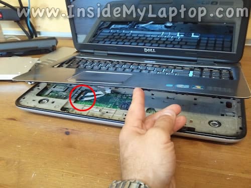
STEP 12.
Turn the palm rest upside down.
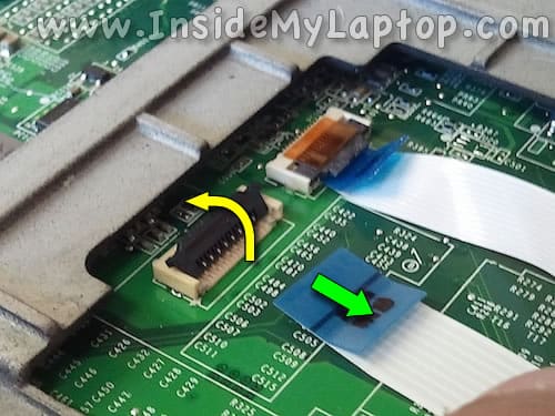
Now you can access the trackpad and power button cable connectors and unlock them.
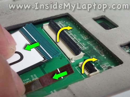
STEP 13.
Here’s how to unlock both connectors.
Lift up the retainer with your fingernail. It will pop up at a 90 degree angle.
Pull the cable from the connector.
STEP 14.
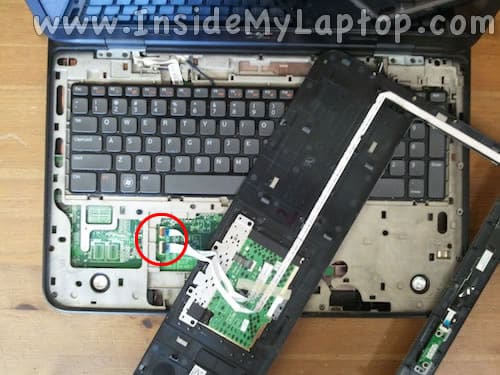
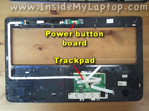
Remove the palm rest assembly from the laptop.
On the back side you can access the trackpad and power button board.
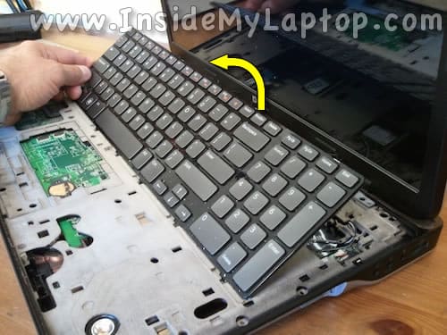
STEP 15.
Lift up the keyboard and place it upside down on the top cover.
STEP 16.
Before you  can remove the keyboard it’s necessary to disconnect the data and backlight cables.
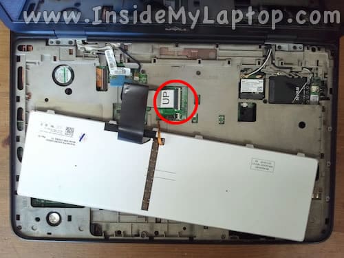
STEP 17.
Unlock both connectors the same way as explained in the step 13.
STEP 18.
Remove two screws securing display hinges on the bottom .

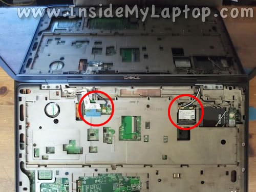
STEP 19.
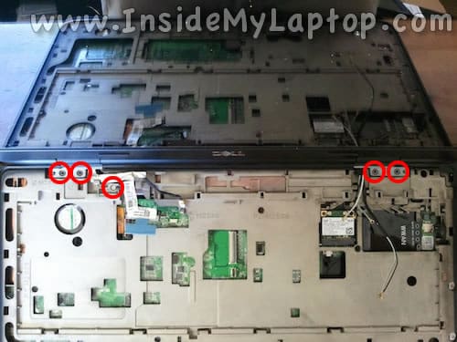
Now it’s necessary to disconnect the display cables and wireless card antennas.
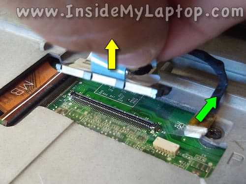
STEP 20.
Disconnect two display cables.
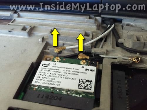
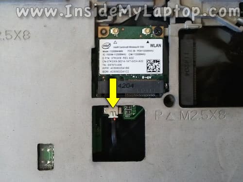
STEP 21.
Unplug both antenna cables from the wireless card.
Un-route all antenna cables from the to guided path on the top cover.
STEP 22.
Remove four screws securing the display hinges and one ground screw.
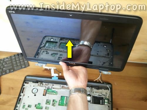
STEP 23.
Lift up the display assembly and separate it from the laptop base.
Remove the display assembly.
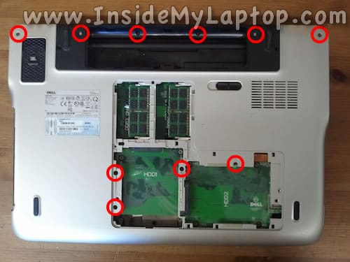
STEP 24.
Remove all screws from the bottom.
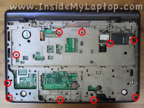
STEP 25.
Remove all screws securing the top cover.
STEP 26.
Disconnect the subwoofer cable.
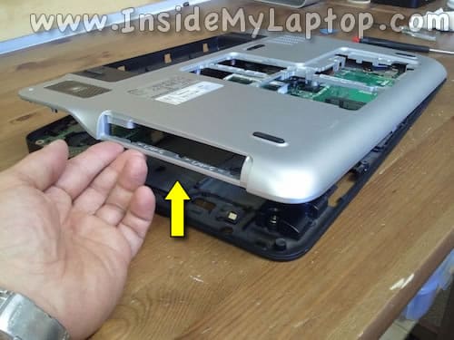
STEP 27.
Now you should be able to lift up and separate the bottom cover from the rest of the laptop.
NOTE: the motherboard secured to the top cover.
It is NOT necessary to remove the display assembly as shown in steps 18-23 in order to remove the bottom cover. You can do it while the display is still attached to the laptop.
STEP 28.
Remove the bottom cover.
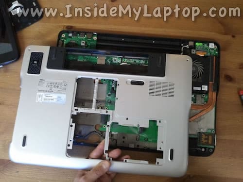
STEP 29.
The bottom cover has been removed.
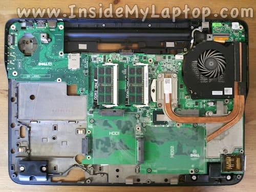
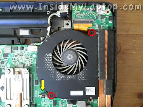
STEP 30.
Remove two screws securing the cooling fan.
Unplug the fan cable from the motherboard.
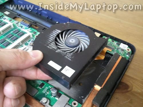
STEP 31.
Remove the cooling fan.
It’s ready for cleanup or replacement.
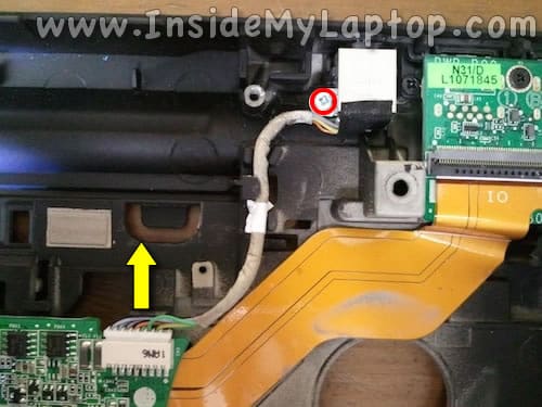
STEP 32.
Remove one screw securing the power connector (DC jack).
Unplug the power connector cable from the motherboard.
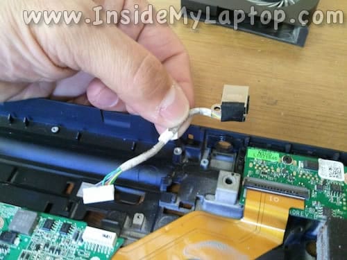
STEP 33.
Now you can remove the power connector and replace it with a new one if necessary.
Marco
A question about the display cables you detach at step 20: the left one is normal video, but what is the small right one??
Thanks
IML Tech
Marco,
This is the webcam cable.
juan c
hello! Hello!
very good contribution, my question is … why not start my computer after the disassemble and went back to join. I press the power button, turn on all the lights but not turn the screen and the fan cooler, makes a noise from the speakers and then turns off. what is? help!