Today I will walk you through a Lenovo YOGA 900-13ISK2 model 80UE disassembly. I will show how to remove most important internal components including the motherboard and display panel.
These instructions also should work for Lenovo Yoga 300-13ISK model 80MK laptop.
WARNING: Lenovo YOGA 900-13ISK2 motherboard has lots of fragile cable connectors. Work slowly while opening up the connectors and disconnecting the cables. Use your best judgement to figure out how much force to apply to unlock a connector.
STEP 1.
Remove ten Torx5 screws securing the bottom cover.

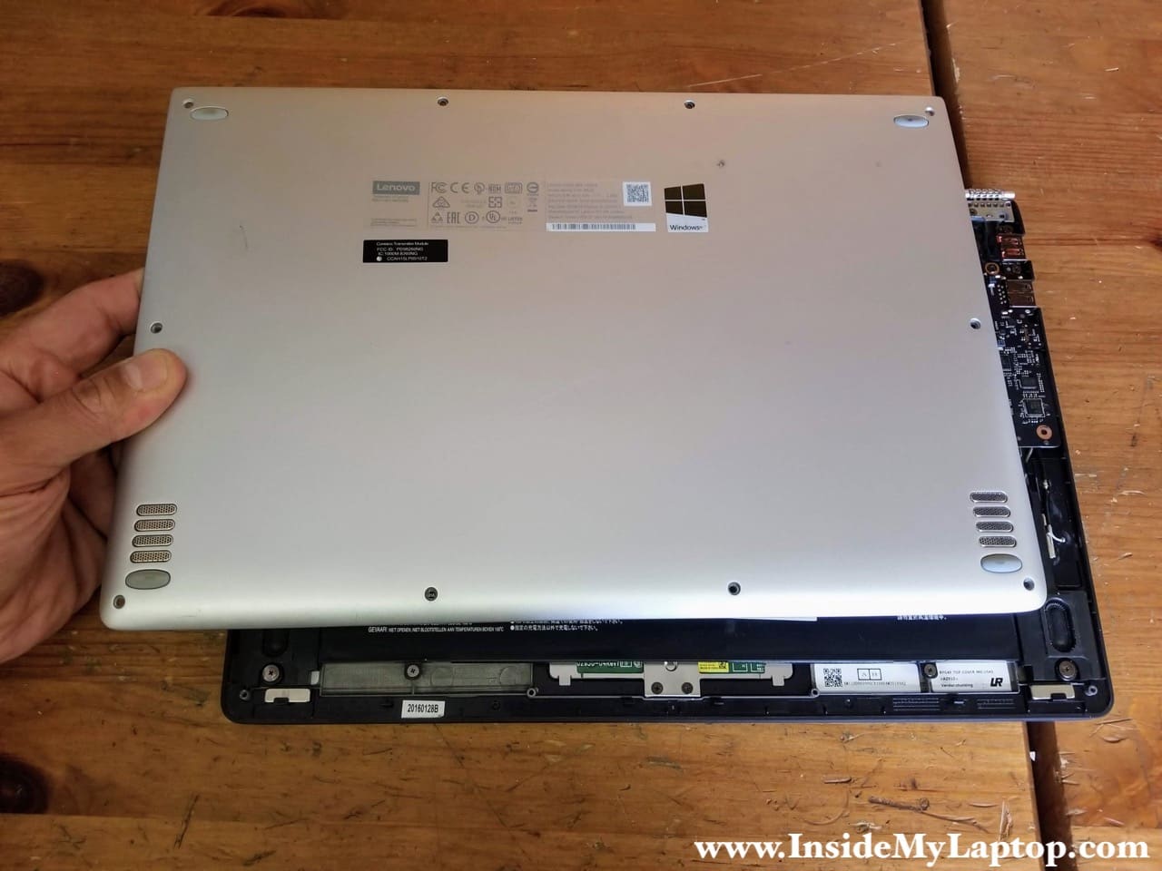
STEP 2.
Using a thin case opener tool start separating the bottom cover from the palmrest assembly. Move the tool along the side and pry up a little bit to disengage hidden latches.

STEP 3.
Remove the bottom cover.
STEP 4.
Remove five screws securing the battery.
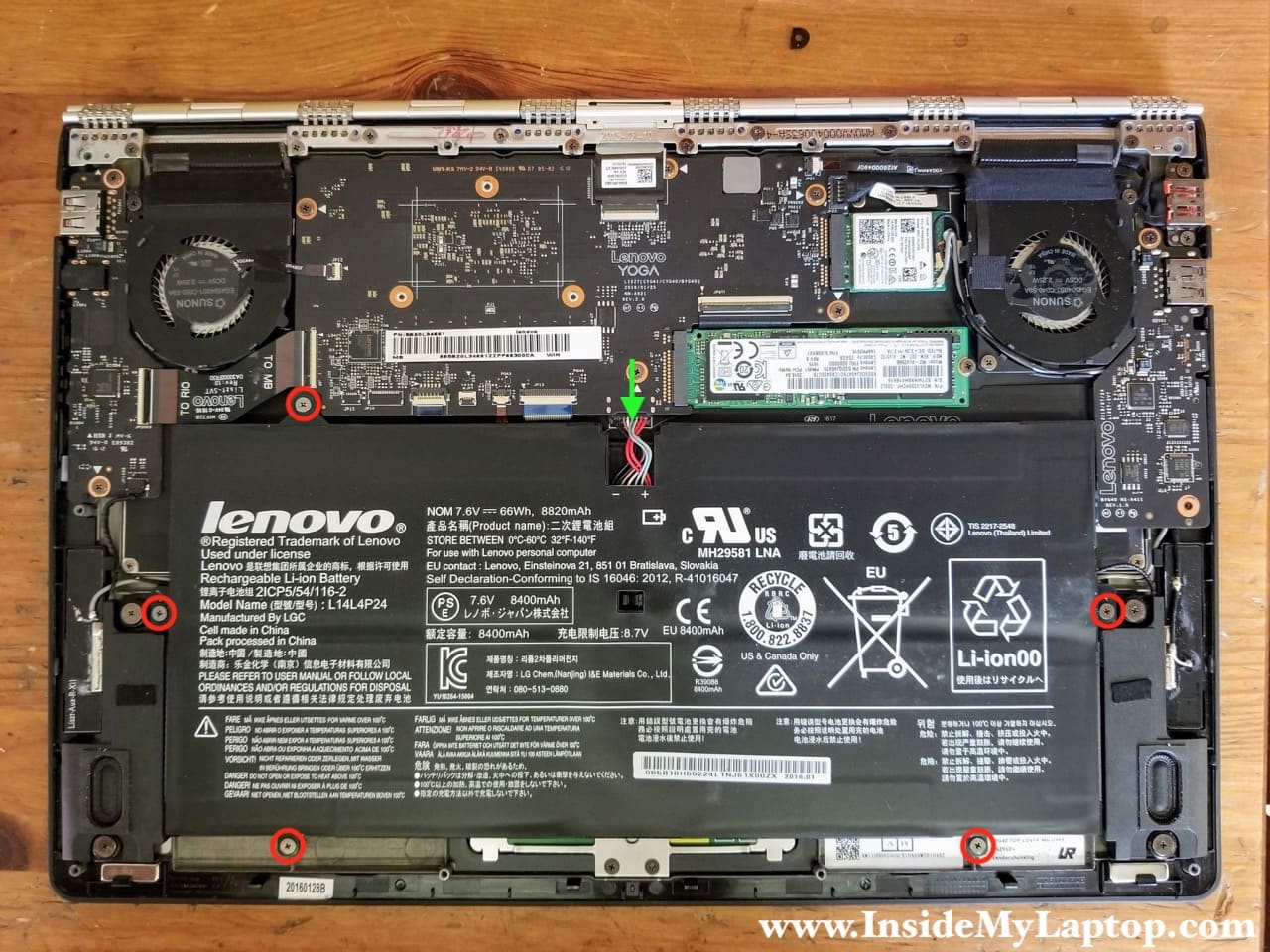
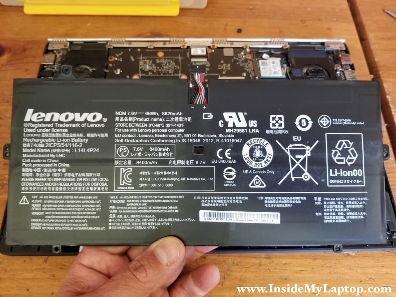
STEP 5.
Unplug the battery from the motherboard and remove it.
Replacement battery model L14L4P24.
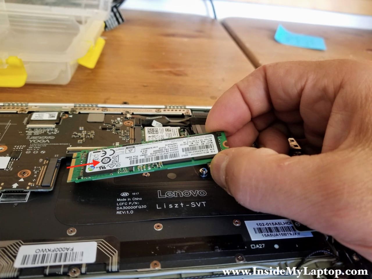
STEP 6.
Remove one screw securing the solid stat drive.
Pull the solid state drive out. This is m.2 NVMe PCIe solid state drive.
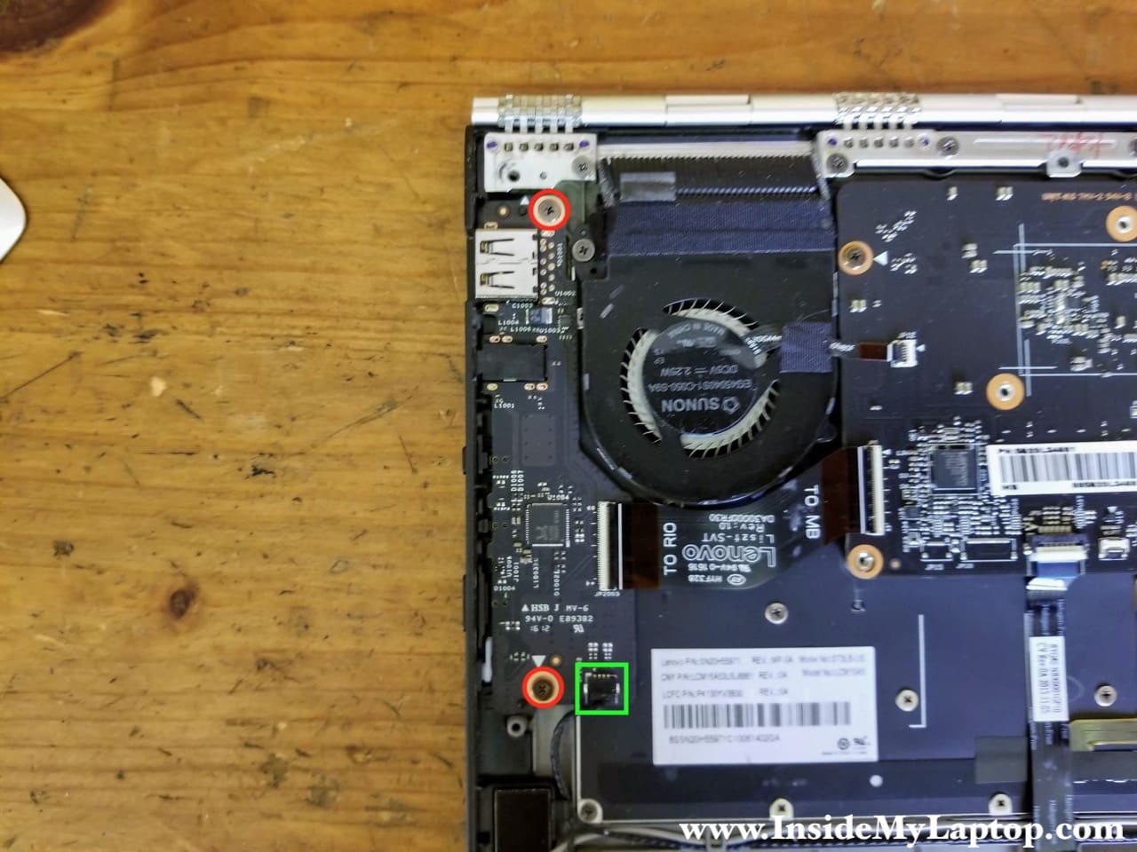
STEP 7.
Remove two screws securing the power button board.
Disconnect the speaker cable from the board.
STEP 8.
Carefully disconnect the power button board cable from the motherboard.
Unlock the connector first by lifting up the locking tab. After that pull the cable out.
STEP 9.
Remove the power button board.
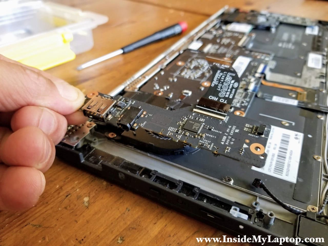
STEP 10.
Remove one screw securing the USB SD card reader board.
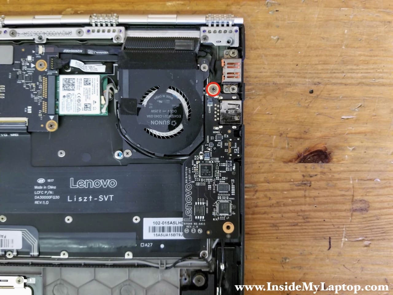
STEP 11.
Turn the board over to access the cable connector.
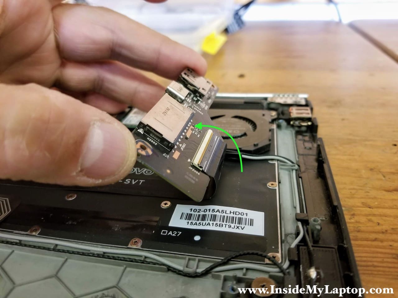
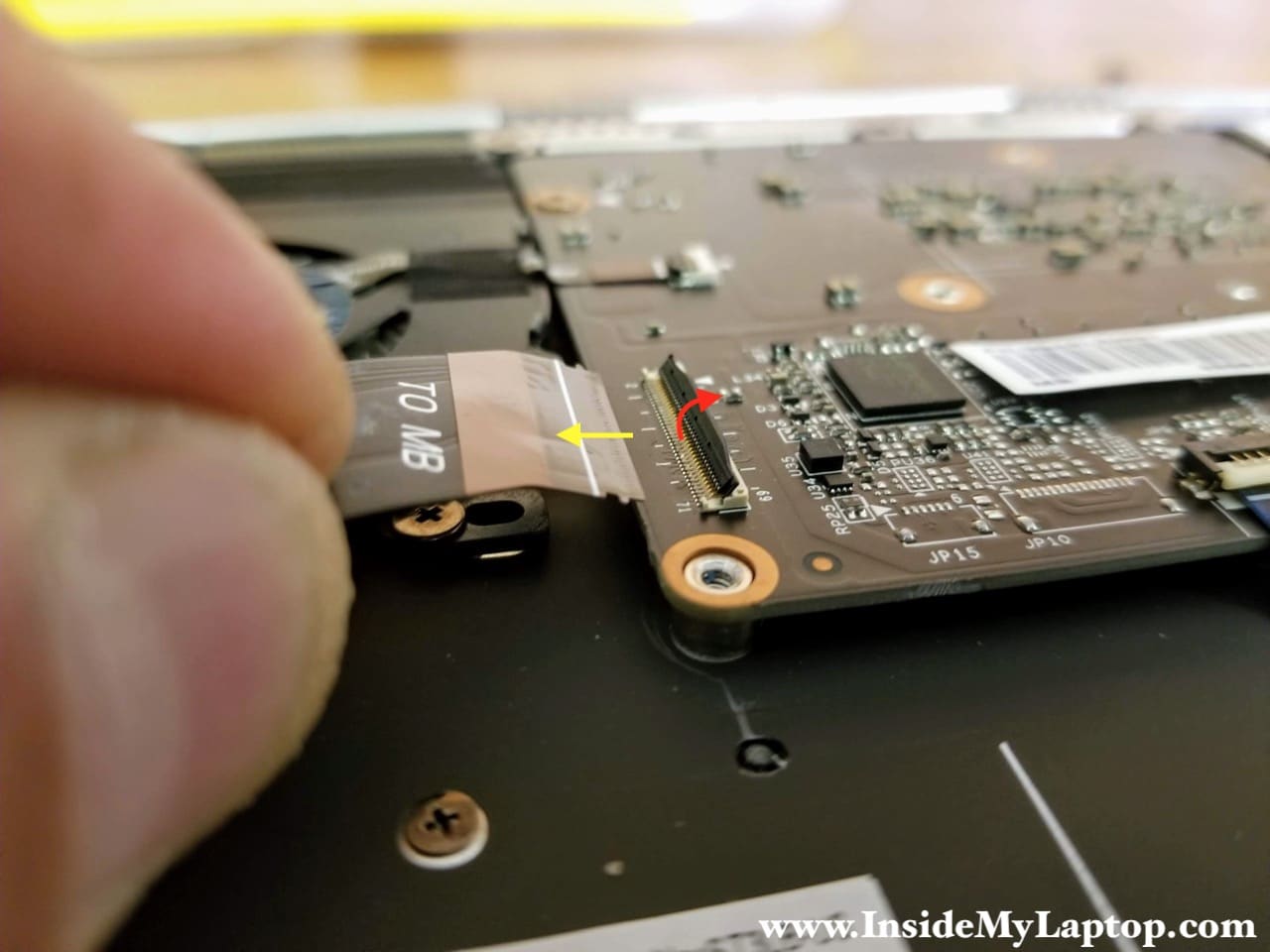
STEP 12.
Unlock the connector by lifting up the locking tab (red arrow) and pull the cable out (yellow arrow).
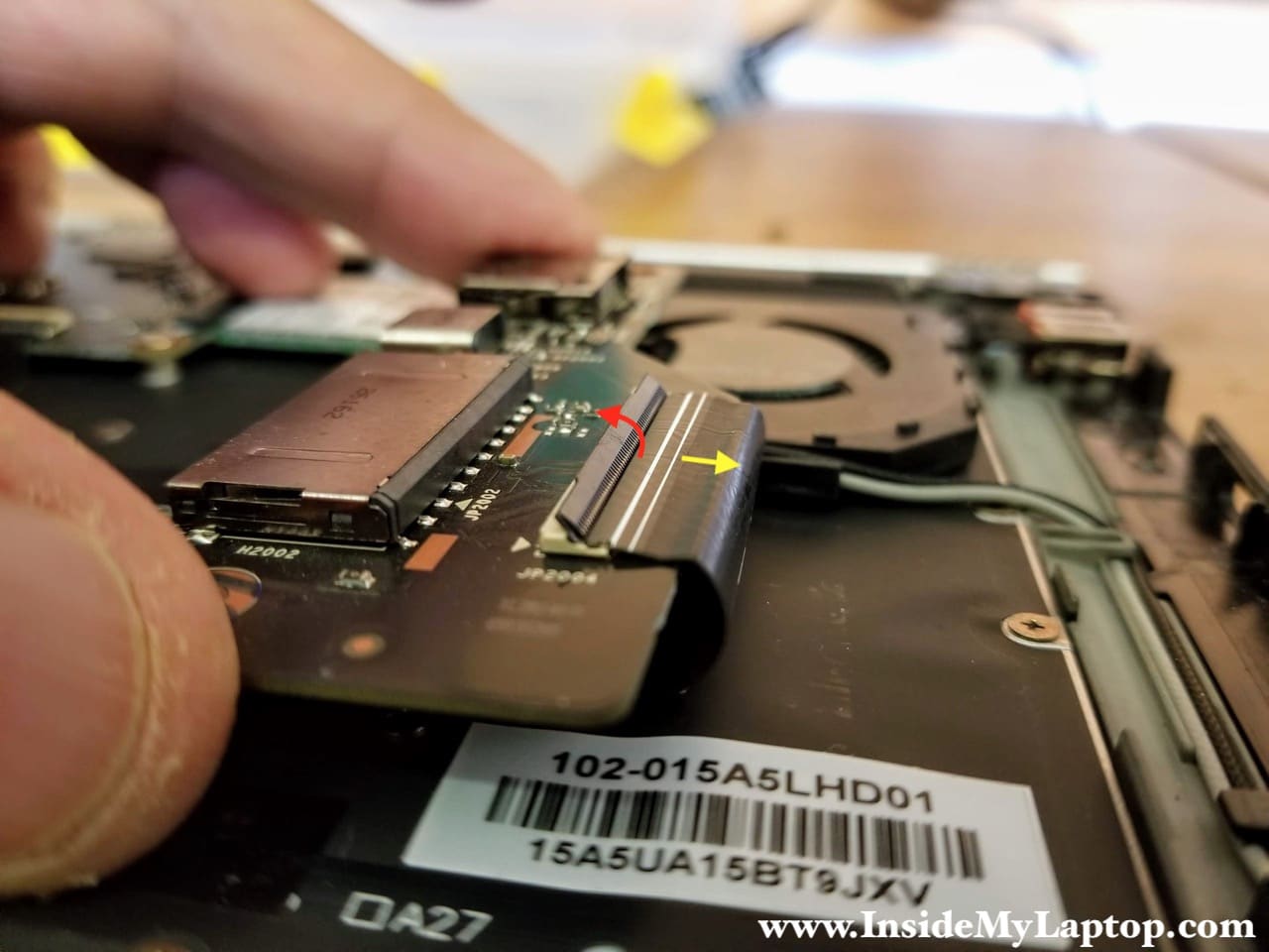
STEP 13.
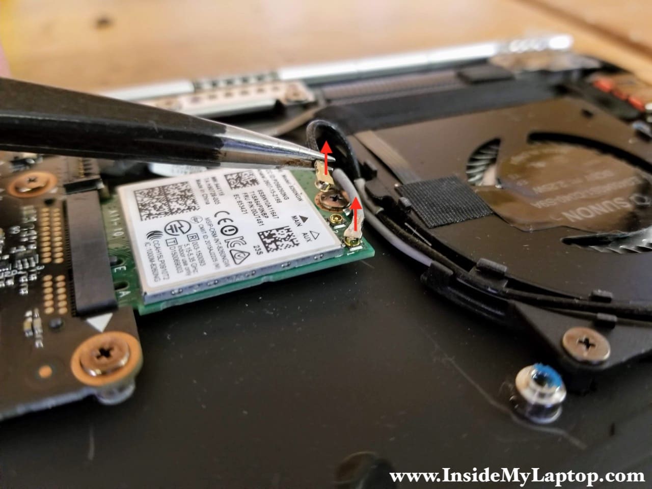
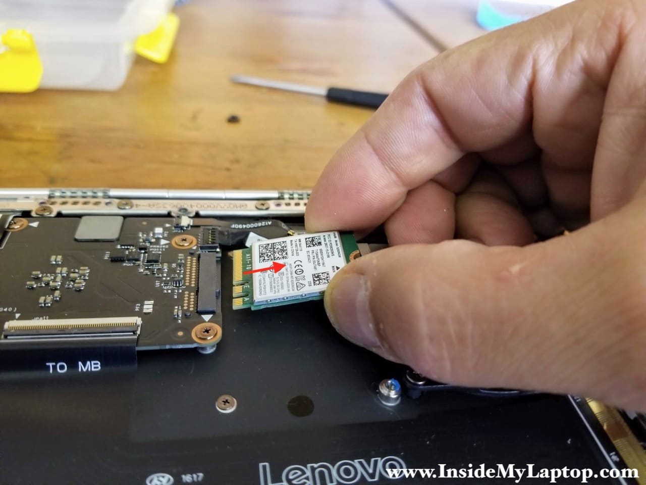
Disconnect both antenna cables from the wireless card. Lift up each golden connector until it unsnaps from the card.
Remove one screw securing the wireless card.
STEP 14.
Remove the wireless card.
STEP 15.
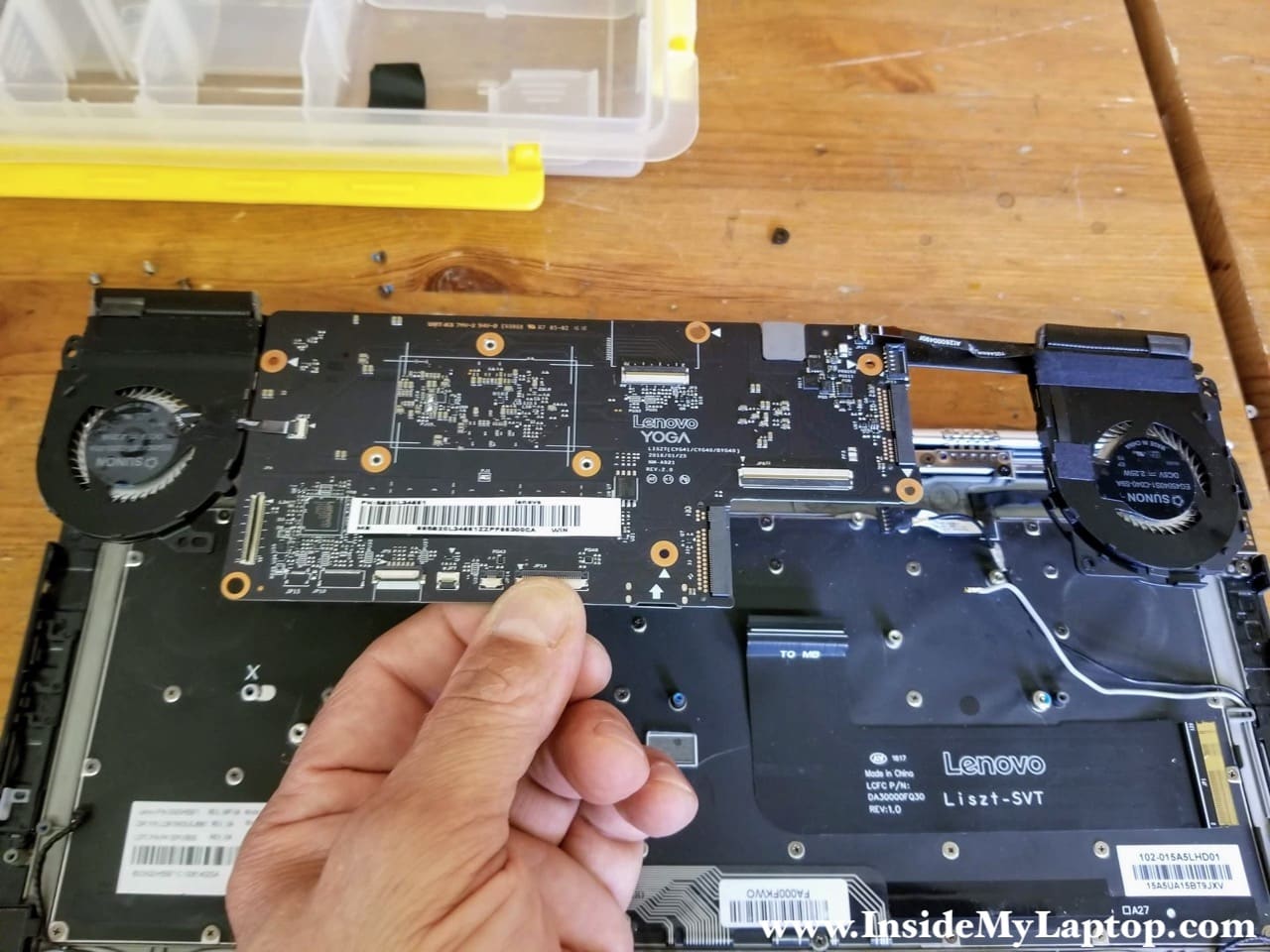
Remove nine screws securing the motherboard and disconnect all cables.
I color-coded all cables:
– Trackpad cable (yellow)
– Keyboard and keyboard backlight cables (orange)
– Display cable (blue)
– USB SD card reader cable (green)
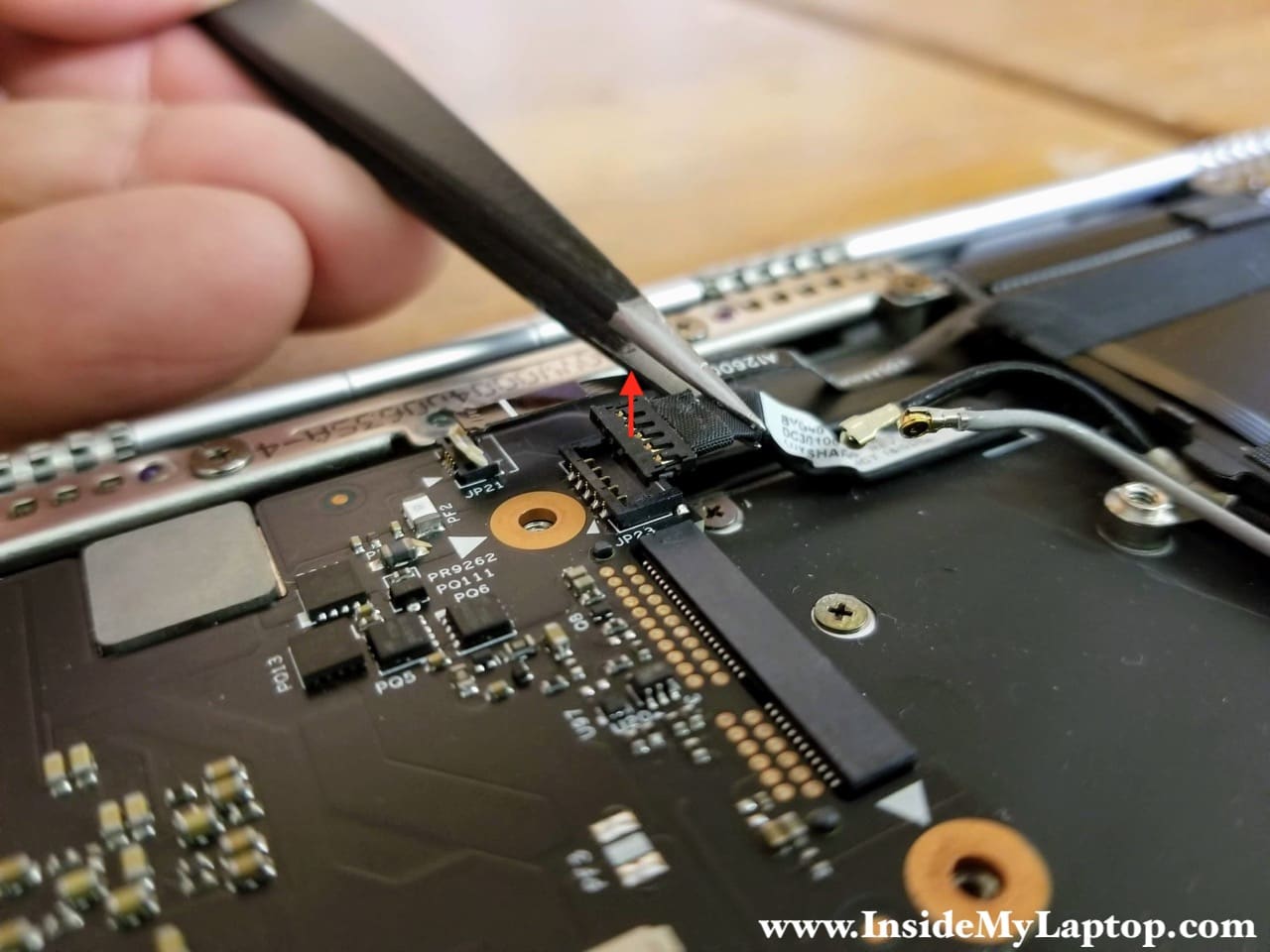
– DC power jack cable (pink)
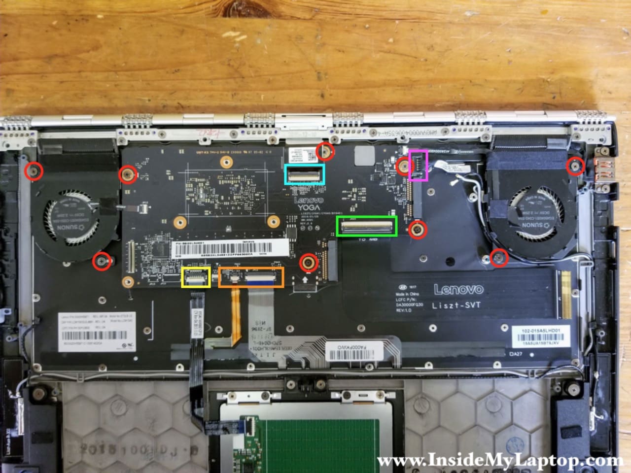
As usual, unlock the connector first before pulling the cable out.

You’ll have to lift up the DC power jack cable connector to disconnect it from the motherboard.
STEP 16.
Unroute wireless card antenna cables from the guided path on the fan.
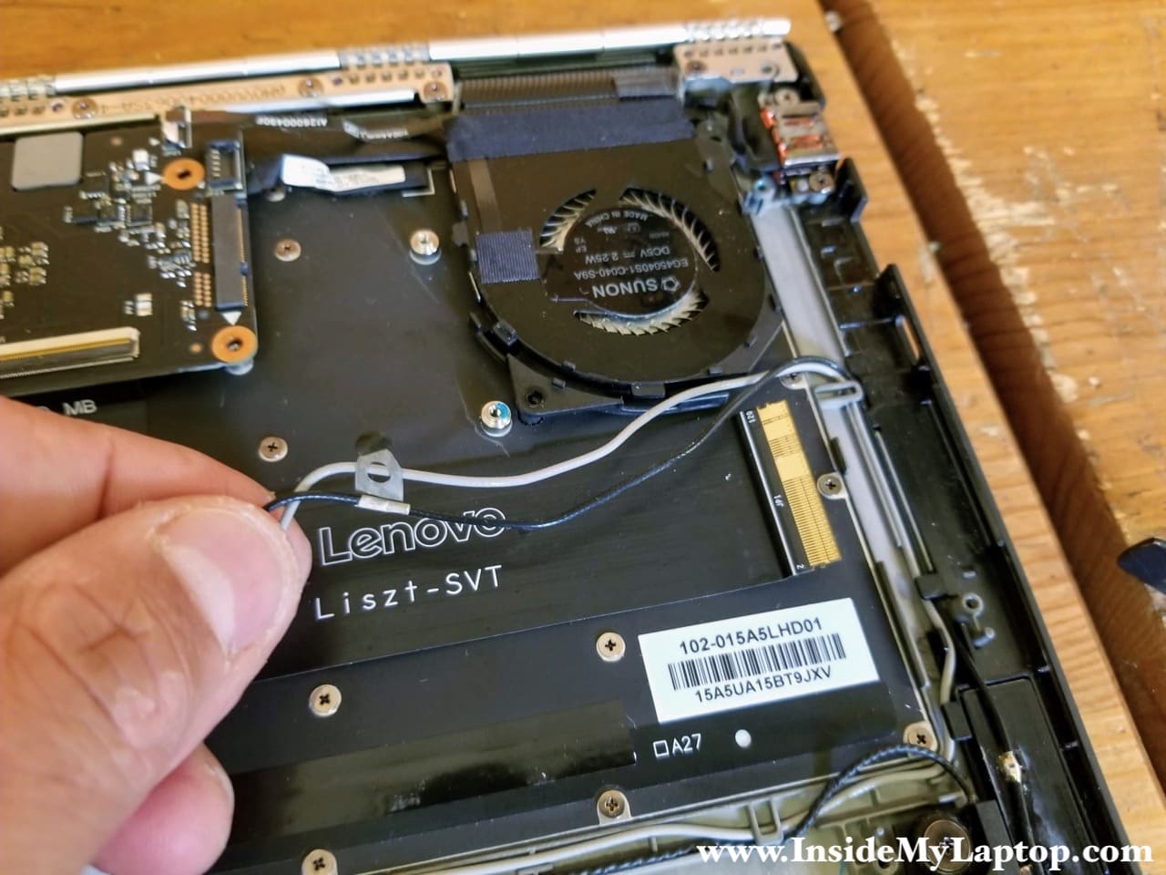
STEP 17.
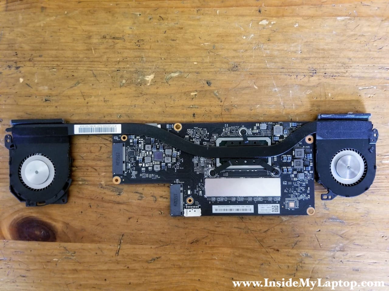
Now you can remove the motherboard.
Both fans are attached to the heatsink with adhesive tape. I’m not sure if you can replace fans separately. Probably it’s necessary to replace the entire heatsink/fan assembly.
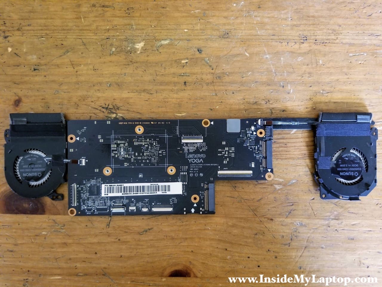
Here’s the other side of the motherboard.
STEP 18.
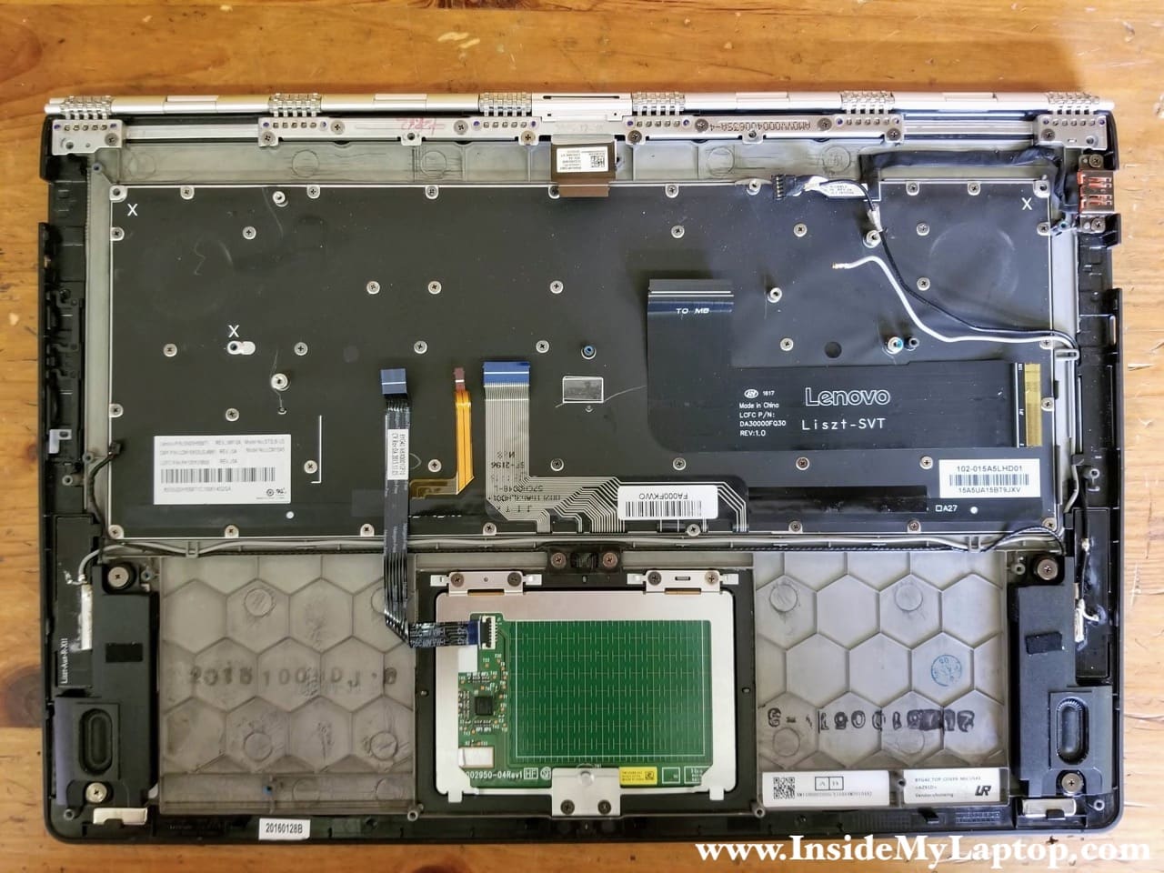
The DC power jack secured to the palmrest by two screws.
It’s necessary to remove the motherboard first in order to remove the DC jack because the harness is routed under the fan.
By the way, in Lenovo YOGA 900-13ISK2 laptop the keyboard is replaceable unlike in many other newer laptops. You’ll have to remove many screws in order to separate the keyboard from the palmrest assembly.
Remove two screws securing the DC jack.
Remove the DC jack harness.
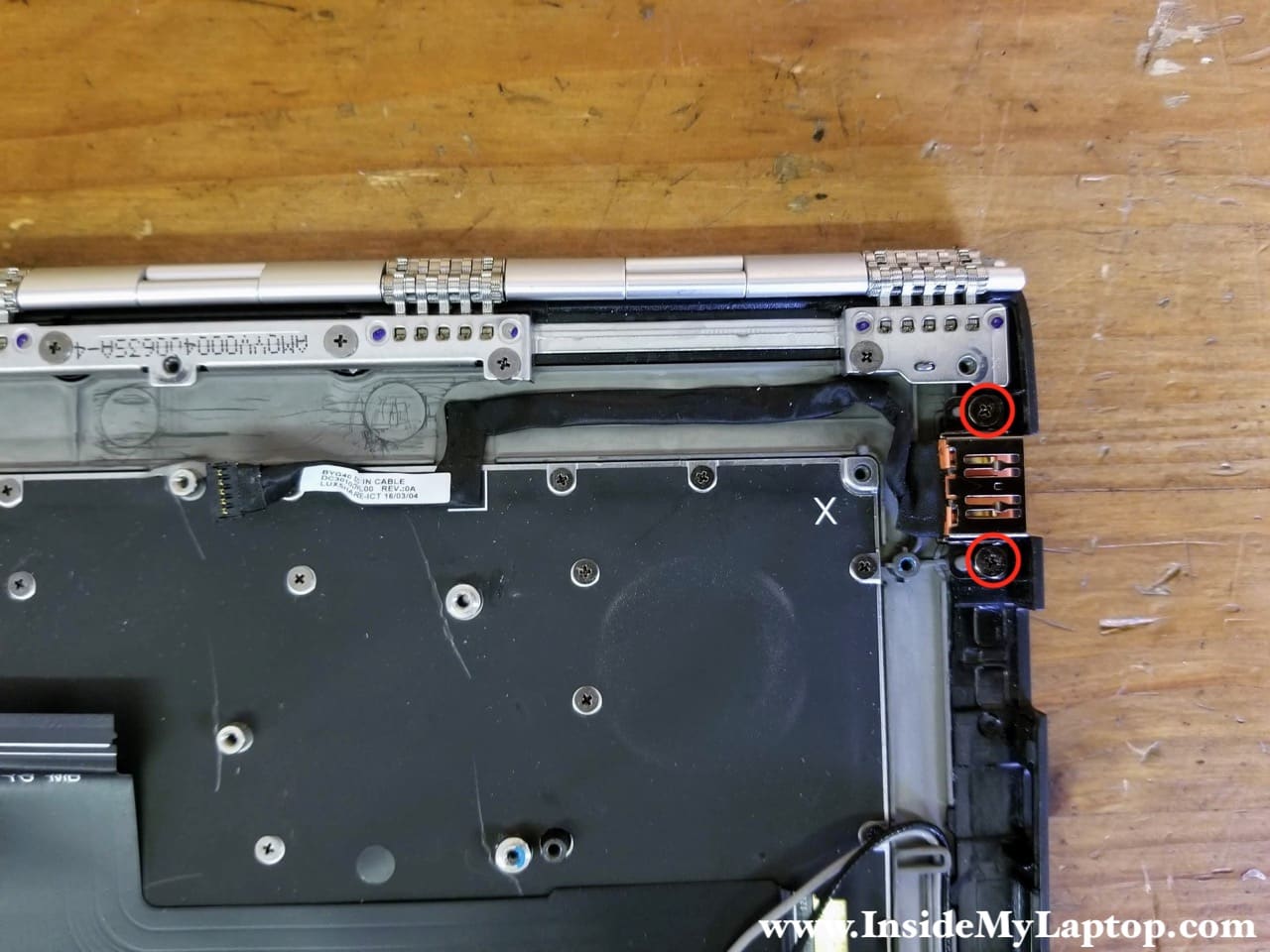
STEP 19.
Open up the display and place the laptop upside down on the edge of the desk.
Remove ten screws securing the display panel to the palmrest assembly.
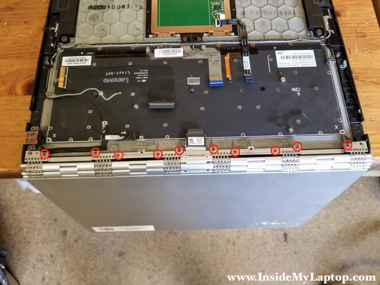
STEP 20.
Now you can separate the display panel and remove it.
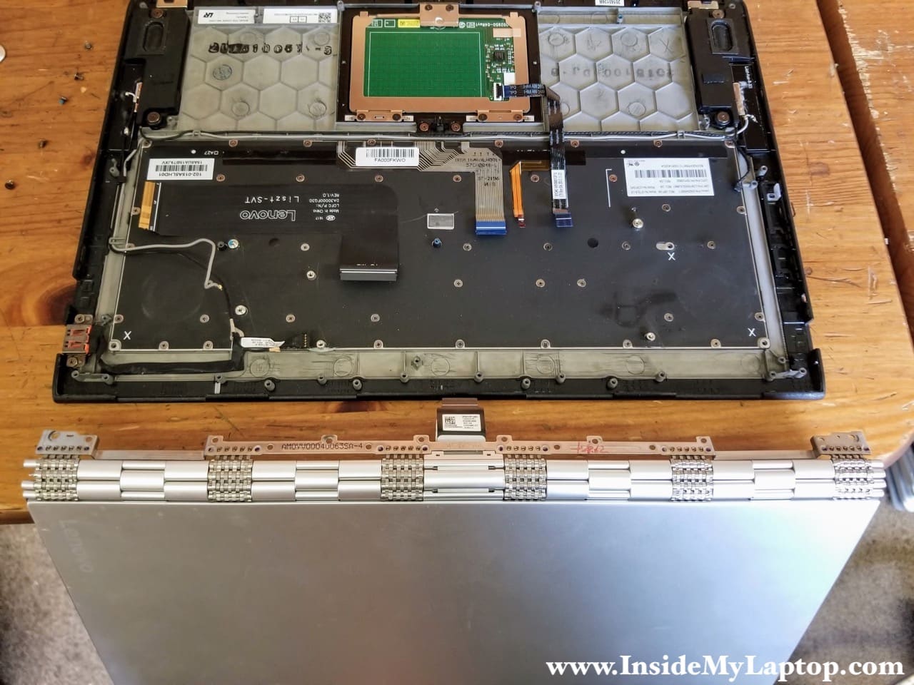
For the display panel disassembly check out the next post: Lenovo Yoga 900-13ISK touchscreen and display cable removal instructions.
Maria
What kind of SSD is it? I searched online but they all look similar. I want to upgrade to 1TB SSD but not sure which one to buy. Please guide me. Thanks.
IML Tech
Maria, this is PCIe NVMe M.2 solid state drive.
Here’s one you can use Samsung 970 EVO Plus SSD 1TB – M.2 NVMe.
Josh
So I have read a lot of different assemblies for opening the back of the laptop. I lost a few screws to the back and I am wondering, is it Torx T4 or Torx T5 to replace the screws holding the bottom cover.
IML Tech
Lenovo Yoga 900 has Torx T5 screws on the bottom.
Jim
AWESOME GUIDE. Great pictures! We took apart my daughter’s Yoga system and replaced a fan with bad bearings. The entire 2-fan assembly only cost $13 on eBay, and with your guide, the machine is as good as new. THANKS