In this guide I will show how to disassemble Dell XPS 13 9343 9350 9360 Ultrabooks.
These Dell XPS 13 ultrabooks were announced and released as follows: 9343 (Early 2015), 9350 (Late 2015), 9360 (Late 2016).
I’m taking it apart in order to replace failed keyboard but you can use this teardown guide for accessing and replacing any other internal component.
STEP 1.
Remove eight torx T5 screws from the bottom cover.
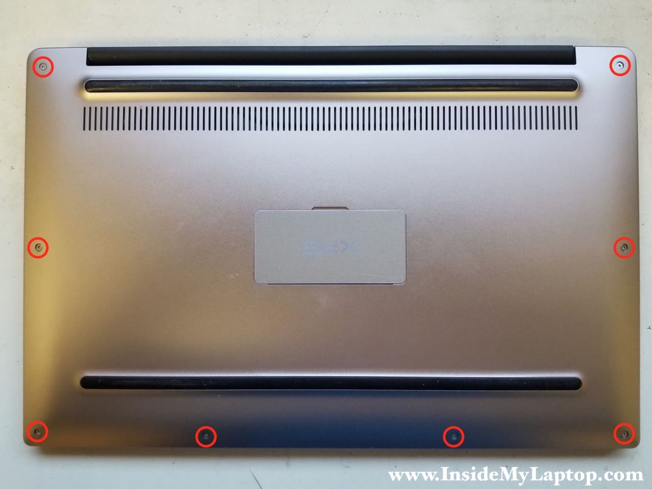
STEP 2.
Remove one more Phillips screw located under the magnetic hatch.

STEP 3.
Start separating the bottom cover from the rest of the laptop.
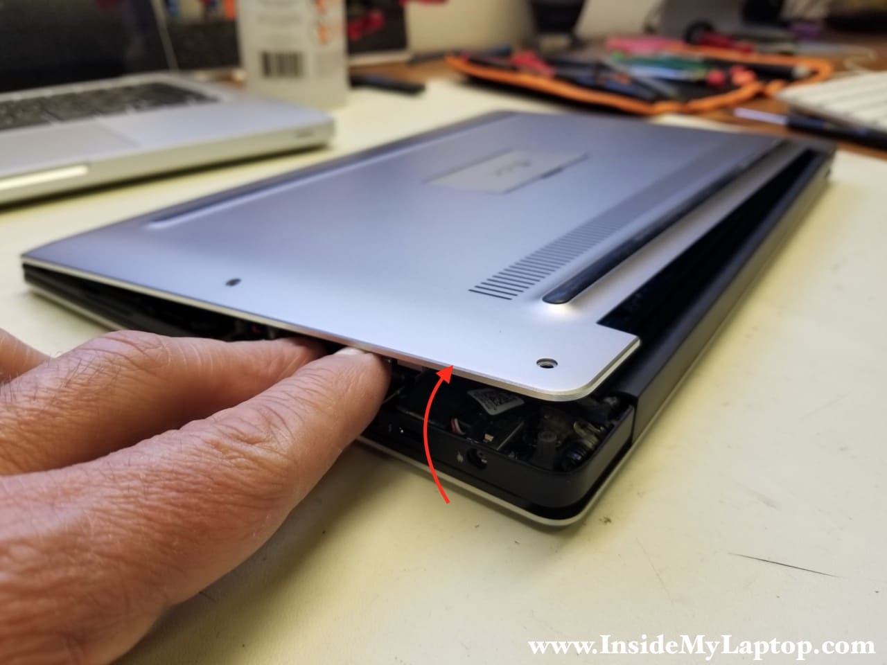
It might be easier to remove the bottom cover if you lift up the lower side first and after that pull it towards yourself away from the hinges.
The bottom cover has small knobs that engage the top case at the upper side.

STEP 3.
Remove four screws securing the battery.
The speaker cables attached to the battery by electrical tape (yellow arrows). Separate the cables from the battery.

STEP 4.
Disconnect the battery connector from the motherboard and remove it.

The battery looks swollen and definitely needs to be replaced.

STEP 5.
Remove four screws securing the left and right speakers.

STEP 6.
Remove both speakers and disconnect the cable.

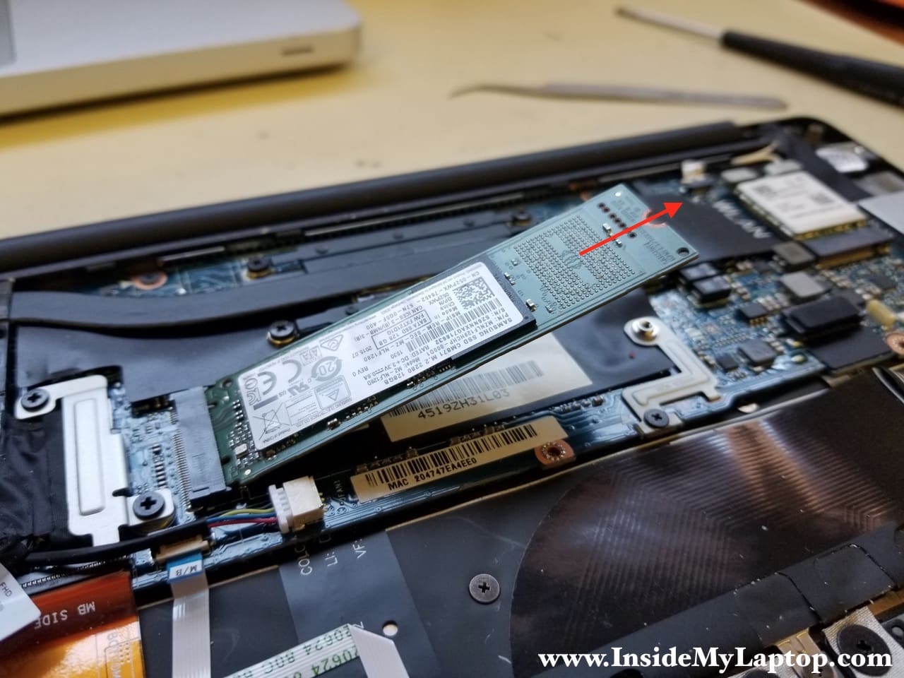
STEP 7.
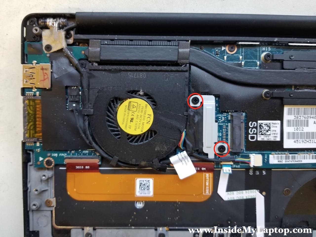
The solid state drive secured by one screw. After you remove the screw, the SSD will pop up at a 25 degree angle.
Pull the SSD out of the socket. This is m.2 SATA III solid state drive.
STEP 8.
Remove two screws securing the display cable connector bracket.
Remove the bracket.
STEP 9.
Disconnect the display video cable from the motherboard.
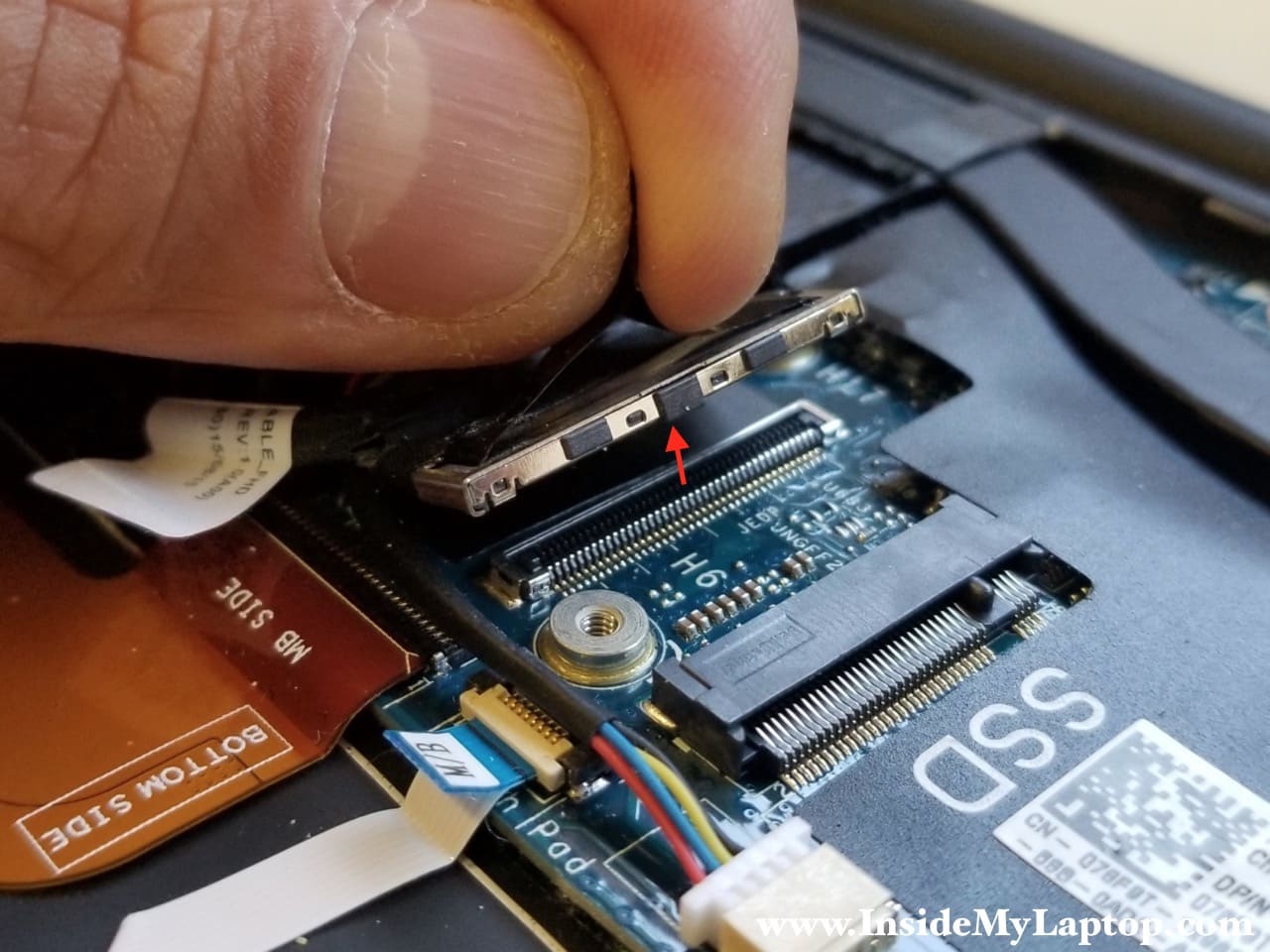
STEP 10.
The display cable is routed in the guided path along the side of the cooling fan.
Separate this cable from the fan and move it aside.
STEP 11.
Remove two screws securing the cooling fan.
Disconnect the fan cable.

STEP 12.
On the lower side the fan bracket is seated on a metal stud.
Lift up the lower left side of the motherboard just enough to separate the fan bracket from the stud.

STEP 13.
Remove the fan. Now it can be replaced if necessary.

STEP 14.
Disconnect the flex cable connecting the motherboard with the USB/SD card board.
The flex cable is attached to the keyboard by adhesive tape.
Be very careful wit the connector, it’s thin and fragile.
Unlock the connector by lifting up the tab (red arrow). Pull the cable out.

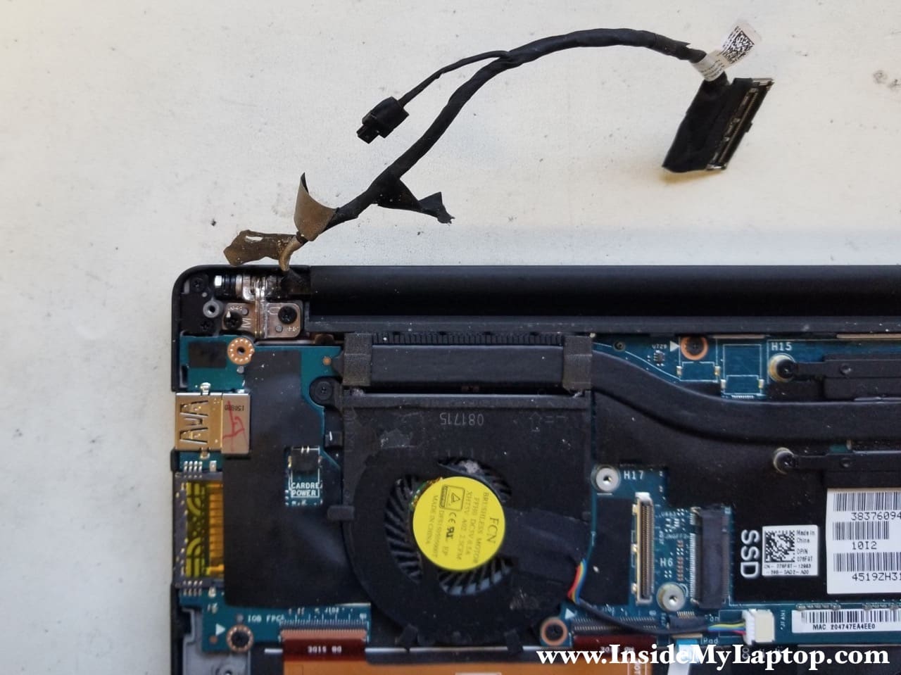
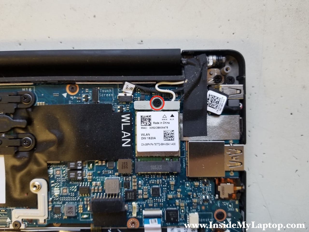
STEP 15.
Remove one screw securing the wireless card bracket. Remove the bracket.
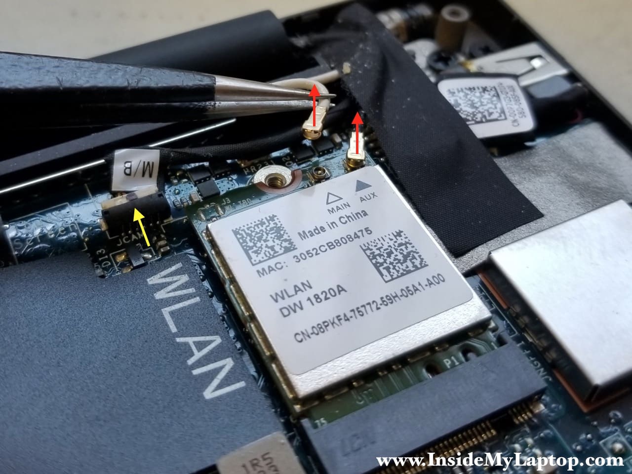
STEP 17.
Disconnect Wi-Fi antenna cables from the wireless card (red arrows).
Unplug the display cable (yellow arrow).
Pull the wireless card out of the socket.
STEP 18.
Move disconnected cables aside.
It looks like the DC power jack is easily accessible but the cable is routed under the motherboard (shown in the step 21).
In order to remove the DC jack you will have to remove the motherboard first.

STEP 18.
Disconnect the DC jack cable.

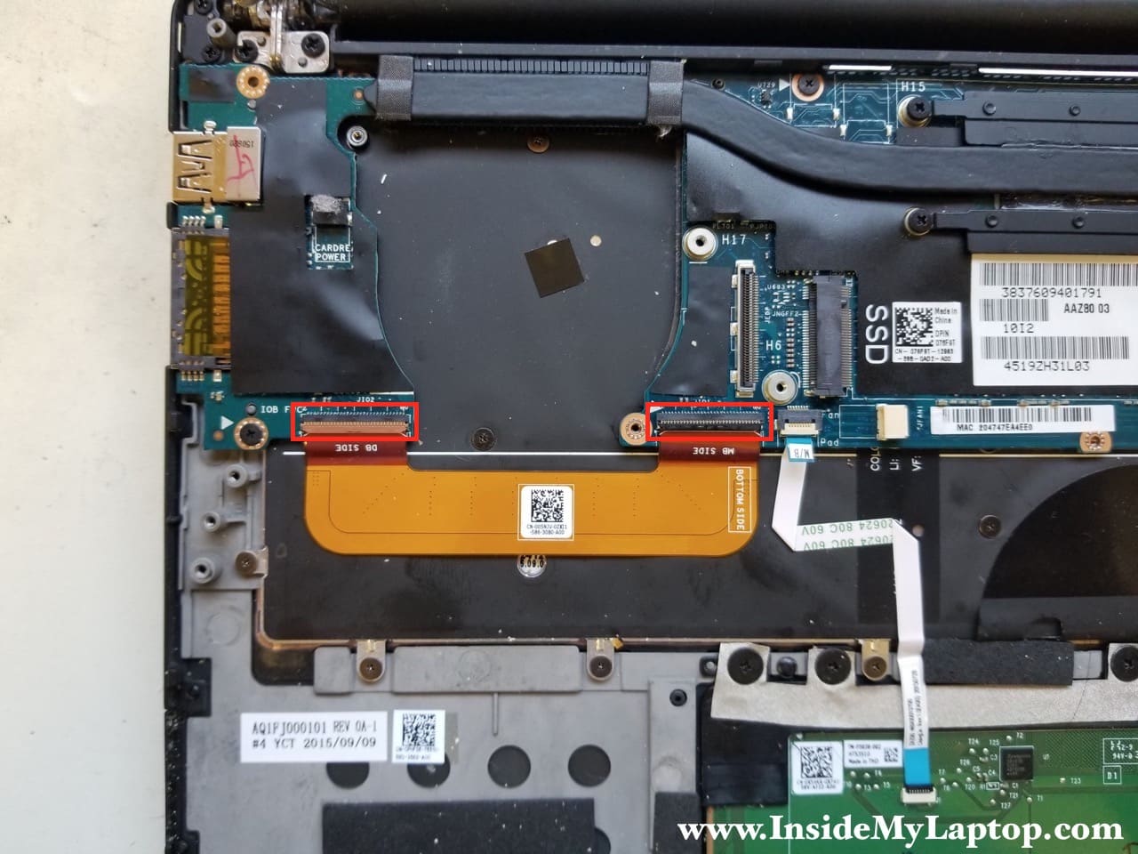
STEP 19.
Remove five screws.
Disconnect two cables.

Before you pull the cable out, you have to unlock the connector by lifting up the locking tab (red arrow).

STEP 20.
Now you can remove the motherboard.
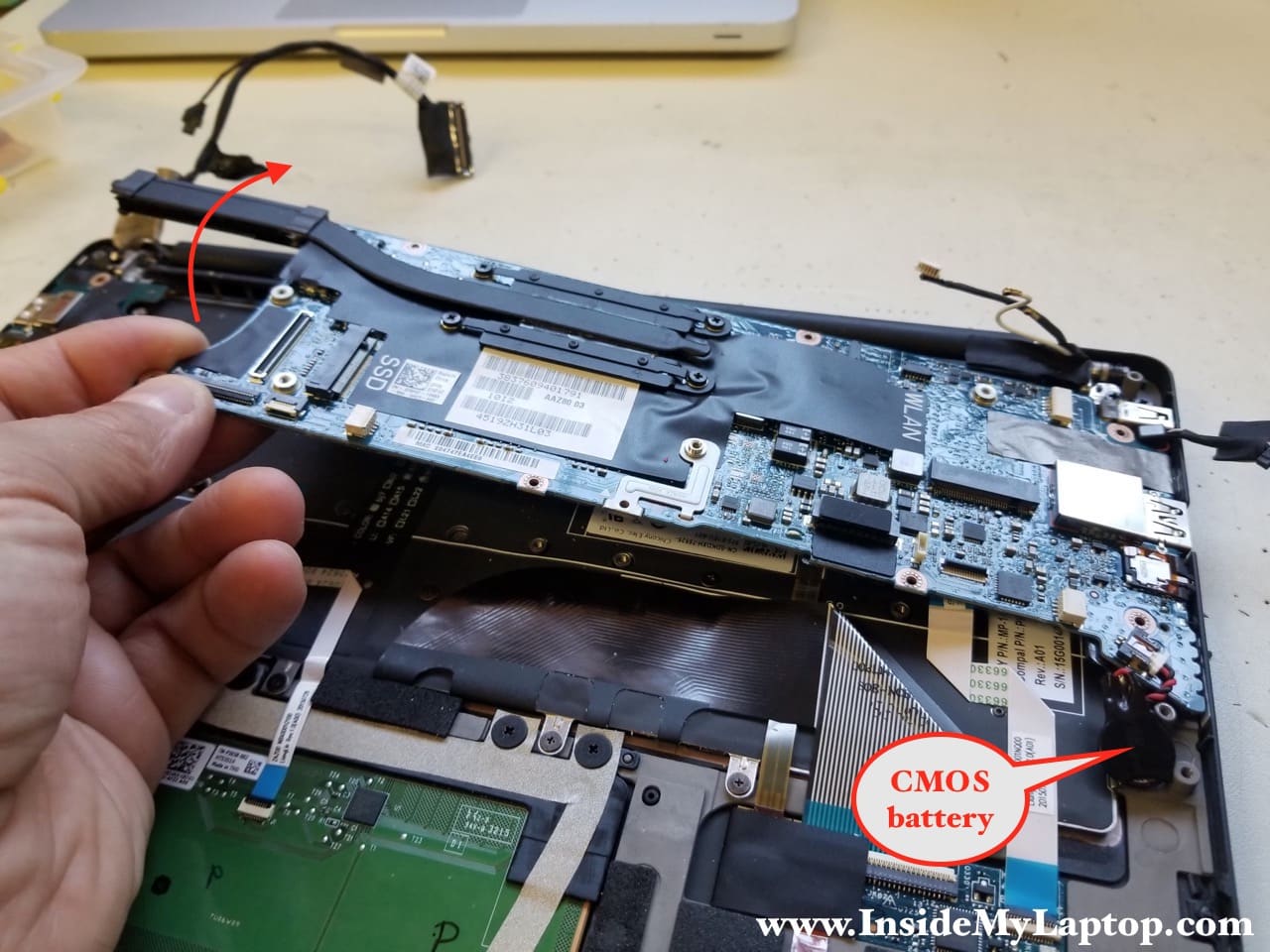
In Dell XPS 13 9343 9350 9360 Ultrabooks the memory (RAM) is soldered to the motherboard and cannot be removed or upgraded.

STEP 21.
Remove one screw securing the DC jack to the top case.
Do you see how the DC jack harness routed?

STEP 21.
Now you can remove the DC power jack and replace it if necessary.

STEP 22.
Peel off the tape and disconnect the keyboard data and backlight cables.

STEP 23.
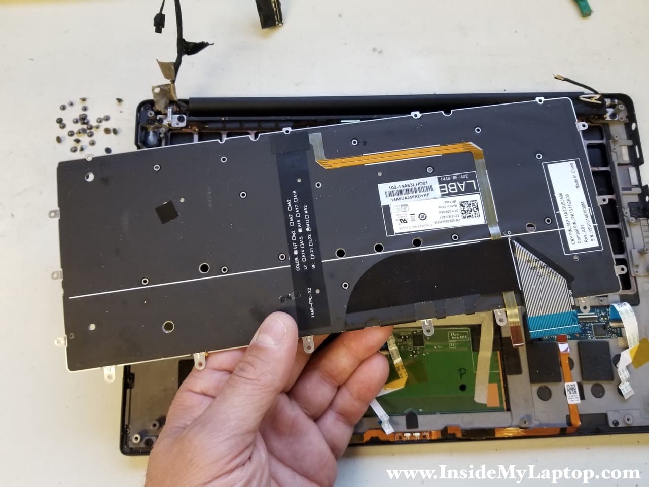
In Dell XPS 13 9343 9350 9360 Ultrabooks there are 28 screws securing the keyboard to the top case.
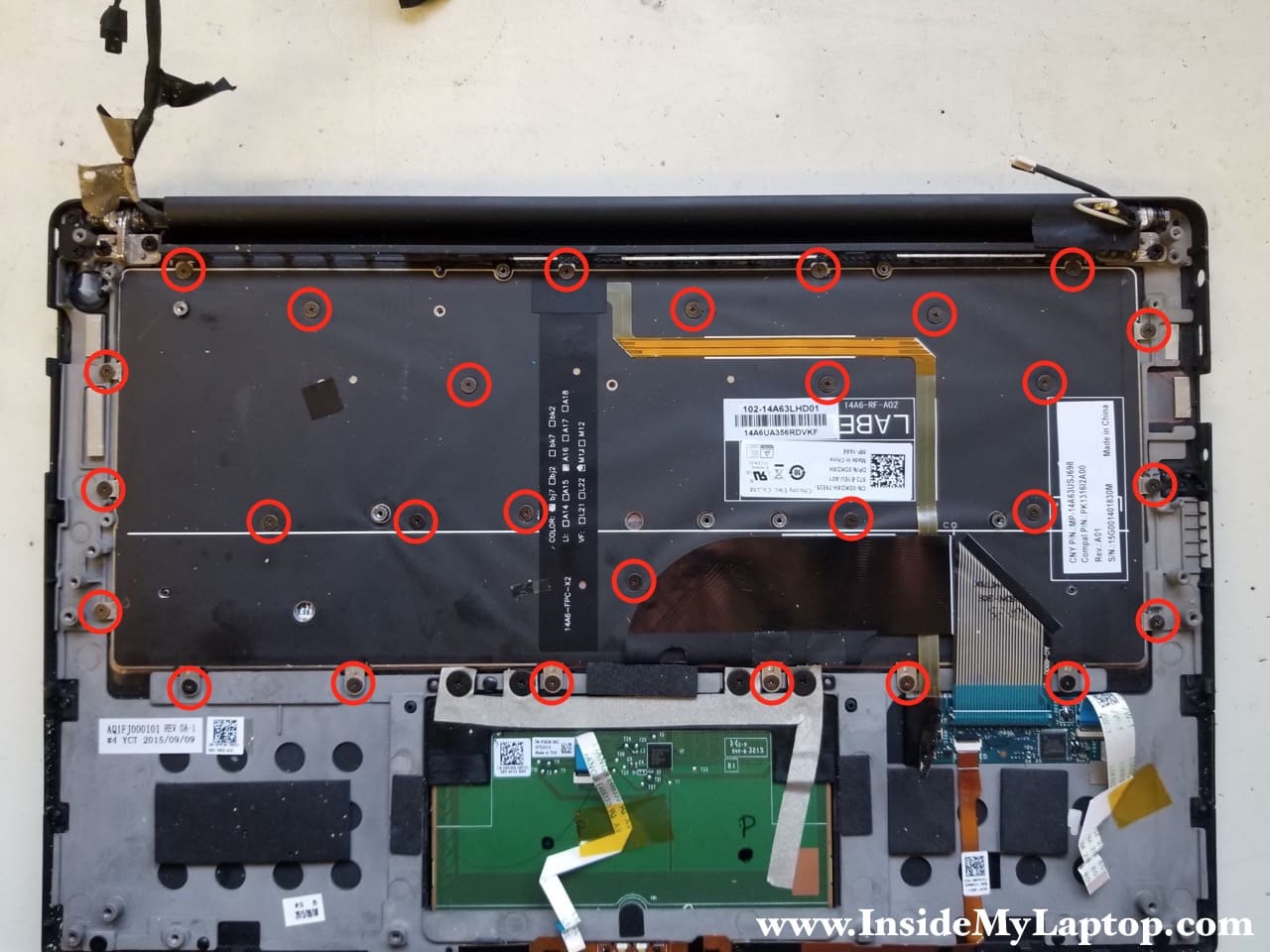
After all screws are removed, you can remove and replace the keyboard.
STEP 24.
The USB/SD card board is mounted by one screw.
This board also can be easily removed and replaced.
